
Frequency Inverter
Convertidor de Frecuencia
Inversor de Frequência
CFW700
Motors | Automation | Energy | Transmission & Distribution | Coatings
Quick Parameter Reference, Faults and Alarms
Referencia Rápida de los Parámetros, Fallas y Alarmas
Referência Rápida dos Parâmetros, Falhas e Alarmes

Quick Parameter Reference,
Faults and Alarms
Series: CFW700
English
Document: 10000849536 / 04
Software Version: 2.0X
Date: 01/2017


CFW700 | 3
Quick Parameter Reference, Faults and Alarms
English
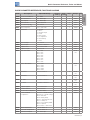
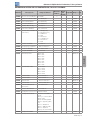
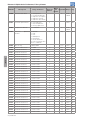
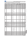
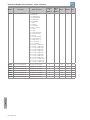
QUICK PARAMETER REFERENCE, FAULTS AND ALARMS
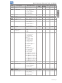
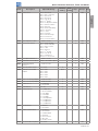
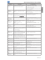
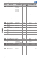
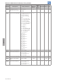
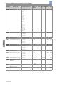
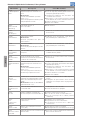
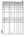
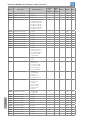
Param. Description Adjustable Range
Factory
Setting
User
Setting
Prop. Groups Pag.
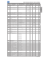
P0000 Access to Parameters 0 to 9999 0 5-1
P0001 Speed Reference 0 to 18000 rpm ro READ 16-1
P0002 Motor Speed 0 to 18000 rpm ro READ 16-1
P0003 Motor Current 0.0 to 4500.0 A ro READ 16-1
P0004 DC Link Voltage (U
d
) 0 to 2000 V ro READ 16-2
P0005 Motor Frequency 0.0 to 1020.0 Hz ro READ 16-2
P0006 VFD Status 0 = Ready
1 = Run
2 = Undervoltage
3 = Fault
4 = Self-Tuning
5 = Configuration
6 = DC Braking
7 = STO
ro READ 16-2
P0007 Motor Voltage 0 to 2000 V ro READ 16-3
P0009 Motor Torque -1000.0 to 1000.0 % ro READ 16-3
P0010 Output Power 0.0 to 6553.5 kW ro READ 16-4
P0011 Output Cos phi 0.00 to 1.00 ro READ 16-4
P0012 DI8 to DI1 Status Bit 0 = DI1
Bit 1 = DI2
Bit 2 = DI3
Bit 3 = DI4
Bit 4 = DI5
Bit 5 = DI6
Bit 6 = DI7
Bit 7 = DI8
ro READ,
I/O
13-9
P0013 DO5 to DO1 Status Bit 0 = DO1
Bit 1 = DO2
Bit 2 = DO3
Bit 3 = DO4
Bit 4 = DO5
ro READ,
I/O
13-14
P0014 AO1 Value 0.00 to 100.00 % ro READ,
I/O
13-5
P0015 AO2 Value 0.00 to 100.00 % ro READ,
I/O
13-5
P0018 AI1 Value -100.00 to 100.00 % ro READ,
I/O
13-1
P0019 AI2 Value -100.00 to 100.00 % ro READ,
I/O
13-1
P0022 Frequency Input 3.0 to 6500.0 Hz ro READ 13-23
P0023 Software Version 0.00 to 655.35 ro READ 6-1
P0028 Accessories Configuration 0000h to FFFFh ro READ 6-2
P0029 Power Hardware
Configuration
Bit 0 to 5 = Rated Current
Bit 6 and 7 = Rated Voltage
Bit 8 = RFI Filter
Bit 9 = Safety Relay
Bit 10 = (0)24 V/(1) DC Link
Bit 11 = Always 0
Bit 12 = Dyn. Braking IGBT
Bit 13 = Special
Bit 14 and 15 = Reserved
ro READ 6-2
P0030 IGBTs Temperature -20.0 to 150.0 °C ro READ 15-3
P0034 Internal Air Temperature -20.0 to 150.0 °C ro READ 15-3
P0036 Heatsink Fan Speed 0 to 15000 rpm ro READ 16-5

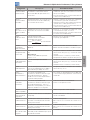
4 | CFW700
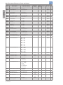
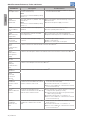
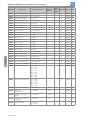
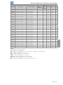
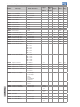
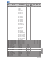
Quick Parameter Reference, Faults and Alarms
English
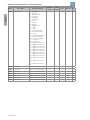
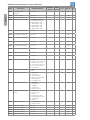
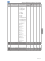
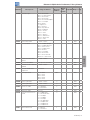
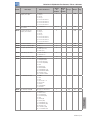
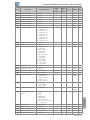
Param. Description Adjustable Range
Factory
Setting
User
Setting
Prop. Groups Pag.
P0037 Motor Overload Status 0 to 100 % ro READ 16-5
P0038 Encoder Speed 0 to 65535 rpm ro READ 16-5
P0039 Encoder Pulse Counter 0 to 40000 ro READ 16-6
P0042 Powered Time 0 to 65535 h ro READ 16-6
P0043 Enabled Time 0.0 to 6553.5 h ro READ 16-6
P0044 kWh Output Energy 0 to 65535 kWh ro READ 16-6
P0045 Enabled Fan Time 0 to 65535 h ro READ 16-7
P0048 Present Alarm 0 to 999 ro READ 16-7
P0049 Present Fault 0 to 999 ro READ 16-7
P0050 Last Fault 0 to 999 ro READ 16-8
P0054 Second Fault 0 to 999 ro READ 16-8
P0058 Third Fault 0 to 999 ro READ 16-8
P0062 Fourth Fault 0 to 999 ro READ 16-8
P0066 Fifth Fault 0 to 999 ro READ 16-9
P0090 Last Fault Current 0.0 to 4500.0 A ro READ 16-9
P0091 Last Fault DC Link Voltage 0 to 2000 V ro READ 16-9
P0092 Last Fault Speed 0 to 18000 rpm ro READ 16-9
P0093 Last Fault Reference 0 to 18000 rpm ro READ 16-10
P0094 Last Fault Frequency 0.0 to 1020.0 Hz ro READ 16-10
P0095 Last Fault Motor Voltage 0 to 2000 V ro READ 16-10
P0096 Last Fault DIx Status Bit 0 = DI1
Bit 1 = DI2
Bit 2 = DI3
Bit 3 = DI4
Bit 4 = DI5
Bit 5 = DI6
Bit 6 = DI7
Bit 7 = DI8
ro READ 16-10
P0097 Last Fault DOx Status Bit 0 = DO1
Bit 1 = DO2
Bit 2 = DO3
Bit 3 = DO4
Bit 4 = DO5
ro READ 16 -11
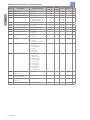
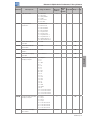
P0100 Acceleration Time 0.0 to 999.0 s 20.0 s BASIC 12-1
P0101 Deceleration Time 0.0 to 999.0 s 20.0 s BASIC 12-1
P0102 Acceleration Time 2 0.0 to 999.0 s 20.0 s 12-1
P0103 Deceleration Time 2 0.0 to 999.0 s 20.0 s 12-1
P0104 Ramp Type 0 = Linear
1 = S Curve
0 12-2
P0105 1
st
/2
nd
Ramp Selection 0 = 1
st
Ramp
1 = 2
nd
Ramp
2 = DIx
3 = Serial
4 = CO/DN/DP
5 = SoftPLC
2 cfg 12-3
P0120 Speed Reference Backup 0 = Inactive
1 = Active
1 12-3
P0121 Keypad Reference 0 to 18000 rpm 90 rpm 12-4
P0122 JOG/JOG+ Reference 0 to 18000 rpm 150 (125)
rpm
12-4
12-5
P0123 JOG- Reference 0 to 18000 rpm 150 (125)
rpm
Vector 12-5
P0132 Maximum Overspeed Level 0 to 100 % 10 % cfg 12-5
P0133 Minimum Speed 0 to 18000 rpm 90 (75) rpm BASIC 12-6

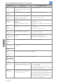
CFW700 | 5
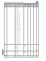
Quick Parameter Reference, Faults and Alarms
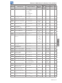
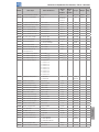
English
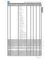
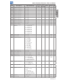
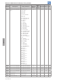
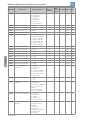
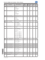
Param. Description Adjustable Range
Factory
Setting
User
Setting
Prop. Groups Pag.
P0134 Maximum Speed 0 to 18000 rpm 1800 (1500)
rpm
BASIC 12-6
P0135 Maximum Output Current 0.2 to 2 x I
nom-HD
1.5 x I
nom-HD
V/f,
VVW
BASIC 9-7
P0136 Manual Torque Boost 0 to 9 According
to the
inverter
model
V/f BASIC 9-2
P0137 Automatic Torque Boost 0.00 to 1.00 0.00 V/f 9-2
P0138 Slip Compensation -10.0 to 10.0 % 0.0 % V/f 9-3
P0139 Output Current Filter 0.0 to 16.0 s 0.2 s V/f,
VVW
9-4
P0142 Maximum Output Voltage 0.0 to 100.0 % 100.0 % cfg, Adj 9-5
P0143 Intermediate Output
Voltage
0.0 to 100.0 % 50.0 % cfg, Adj 9-5
P0144 3 Hz Output Voltage 0.0 to 100.0 % 8.0 % cfg, Adj 9-5
P0145 Field Weakening Speed 0 to 18000 rpm 1800 rpm cfg, Adj 9-5
P0146 Intermediate Speed 0 to 18000 rpm 900 rpm cfg, Adj 9-5
P0150 V/f DC Regulation Type 0 = Ramp Hold
1 = Ramp Acceleration
0 cfg, V/f,
VVW
9-10
P0151 V/f DC Regulation Level 339 to 1000 V 800 V V/f, V V W 9-11
P0152 V/f DC Regulation P Gain 0.00 to 9.99 1.50 V/f,
VVW
9-11
P0153 Dynamic Braking Level 339 to 1000 V 748 V 14-1
P0156 100 % Speed Overload
Current
0.1 to 1.5 x I
nom-ND
1.05 x I
nom-ND
15-4
P0157 50 % Speed Overload
Current
0.1 to 1.5 x I
nom-ND
0.9 x I
nom-ND
15-4
P0158 5 % Speed Overload
Current
0.1 to 1.5 x I
nom-ND
0.65 x I
nom-ND
15-4
P0159 Motor Tripping Class 0 = Class 5
1 = Class 10
2 = Class 15
3 = Class 20
4 = Class 25
5 = Class 30
6 = Class 35
7 = Class 40
8 = Class 45
1 cfg 15-5
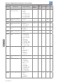
P0160 Speed Regulation
Optimization
0 = Normal
1 = Saturated
0 cfg,
Vector
11-13
P0161 Speed Proportional Gain 0.0 to 63.9 7.4 Vector 11-13
P0162 Speed Integral Gain 0.000 to 9.999 0.023 Vector 11-13
P0163 LOC Reference Offset -999 to 999 0 Vector 11-14
P0164 REM Reference Offset -999 to 999 0 Vector 11-14
P0165 Speed Filter 0.012 to 1.000 s 0.012 s Vector 11-14
P0166 Speed Differential Gain 0.00 to 7.99 0.00 Vector 11-15
P0167 Current Proportional Gain 0.00 to 1.99 0.50 Vector 11-15
P0168 Current Integral Gain 0.000 to 1.999 0.010 Vector 11-15
P0169 Maximum + Torque
Current
0.0 to 350.0 % 125.0 % Vector 11-22
P0170 Maximum - Torque Current 0.0 to 350.0 % 125.0 % Vector 11-22
P0175 Flux Proportional Gain 0.0 to 31.9 2.0 Vector 11-16
P0176 Flux Integral Gain 0.000 to 9.999 0.020 Vector 11-16
P0178 Rated Flux 0 to 120 % 100 % Vector 11-16

6 | CFW700
Quick Parameter Reference, Faults and Alarms
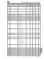
English
Param. Description Adjustable Range
Factory
Setting
User
Setting
Prop. Groups Pag.
P0180 Iq* after I/f 0 to 350 % 10 % Sless 11-17
P0182 Speed for I/f Activation 0 to 90 rpm 18 rpm Sless 11-17
P0183 Current in I/f Mode 0 to 9 1 Sless 11-18
P0184 DC Link Regulation Mode 0 = With Losses
1 = Without Losses
2 = Enable/Disable DIx
1 cfg,
Vector
11-24
P0185 DC Link Regulation Level 339 to 1000 V 800 V Vector 11-25
P0186 DC Link Proportional Gain 0.0 to 63.9 26.0 Vector 11-25
P0187 DC Link Integral Gain 0.000 to 9.999 0.010 Vector 11-25
P0190 Maximum Output Voltage 0 to 600 V 440 V Vector 11-17
P0191 Encoder Zero Search 0 = Inactive
1 = Active
0 12-20
P0192 Encoder Zero Search
Status
0 = Inactive
1 = Finished
0 ro READ 12-20
P0200 Password 0 = Inactive
1 = Active
2 = Change Password
1 HMI 5-2
P0202 Control Type 0 = V/f 60 Hz
1 = V/f 50 Hz
2 = V/f Adjustable
3 = VVW
4 = Sensorless
5 = Encoder
0 cfg 9-5
P0204 Load/Save Parameters 0 = Not Used
1 = Not Used
2 = Reset P0045
3 = Reset P0043
4 = Reset P0044
5 = Load 60 Hz
6 = Load 50 Hz
7 = Load User 1
8 = Load User 2
9 = Save User 1
10 = Save User 2
0 cfg 7-1
P0205 Main Display Parameter
Selection
0 to 1199 2 HMI 5-3
P0206 Secondary Display
Parameter Selection
0 to 1199 1 HMI 5-3
P0207 Bar Graph Parameter
Selection
0 to 1199 3 HMI 5-3
P0208 Main Display Scale Factor 0.1 to 1000.0 % 100.0 % HMI 5-4

CFW700 | 7
Quick Parameter Reference, Faults and Alarms
English
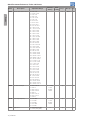
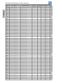
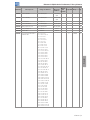
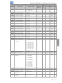
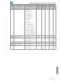
Param. Description Adjustable Range
Factory
Setting
User
Setting
Prop. Groups Pag.
P0209 Main Display Engineering
Unit
0 = None
1 = V
2 = A
3 = rpm
4 = s
5 = ms
6 = N
7 = m
8 = Nm
9 = mA
10 = %
11 = °C
12 = CV
13 = Hz
14 = HP
15 = h
16 = W
17 = kW
18 = kWh
19 = H
20 = According to P0510
21 = According to P0512
22 = According to P0514
23 = According to P0516
3 HMI 5-4
P0210 Main Display Decimal Point 0 = wxyz
1 = wxy.z
2 = wx.yz
3 = w.xyz
4 = According to P0511
5 = According to P0513
6 = According to P0515
7 = According to P0517
0 HMI 5-4
P0211 Secondary Display Scale
Factor
0.1 to 1000.0 % 100.0 % HMI 5-4
P0212 Secondary Display
Decimal Point
0 = wxyz
1 = wxy.z
2 = wx.yz
3 = w.xyz
4 = According to P0511
5 = According to P0513
6 = According to P0515
7 = According to P0517
0 HMI 5-4
P0213 Bar Full Scale 1 to 65535 1 HMI 5-5
P0216 HMI Backlighting 0 to 15 15 HMI 5-5
P0217 Zero Speed Disable 0 = Inactive
1 = Active (N* and N)
2 = Active (N*)
0 cfg 12-7
P0218 Condition to Leave Zero
Speed Disable
0 = Reference or Speed
1 = Reference
0 12-7
P0219 Delay for Zero Speed
Disable
0 to 999 s 0 s 12-8
P0220 LOC/REM Selection
Source
0 = Always LOC
1 = Always REM
2 = LR Key LOC
3 = LR Key REM
4 = DIx
5 = Serial LOC
6 = Serial REM
7 = CO/DN/DP LOC
8 = CO/DN/DP REM
9 = SoftPLC LOC
10 = SoftPLC REM
2 cfg I/O 13-24

8 | CFW700
Quick Parameter Reference, Faults and Alarms
English
Param. Description Adjustable Range
Factory
Setting
User
Setting
Prop. Groups Pag.
P0221 LOC Reference Selection 0 = HMI
1 = AI1
2 = AI2
3 = Sum AIs > 0
4 = Sum AIs
5 = Serial
6 = CO/DN/DP
7 = SoftPLC
0 cfg I/O 13-24
P0222 REM Reference Selection Refer to the P0221 options 1 cfg I/O 13-24
P0223 LOC FWD/REV Selection 0 = Forward
1 = Reverse
2 = FR Key FWD
3 = FR Key REV
4 = DIx
5 = Serial FWD
6 = Serial REV
7 = CO/DN/DP (FWD)
8 = CO/DN/DP (REV)
9 = SoftPLC (FWD)
10 = SoftPLC (REV)
11 = AI2 Polarity
2 cfg I/O 13-25
P0224 LOC Run/Stop Selection 0 = I/O Keys
1 = DIx
2 = Serial
3 = CO/DN/DP
4 = SoftPLC
0 cfg I/O 13-25
P0225 Selection of JOG – LOCAL
Situation
0 = Inactive
1 = JOG Key
2 = DIx
3 = Serial
4 = CO/DN/DP
5 = SoftPLC
1 cfg I/O 13-26
P0226 REM FWD/REV Selection Refer to the P0223 options 4 cfg I/O 13-25
P0227 REM Run/Stop Selection 0 = I/O Keys
1 = DIx
2 = Serial
3 = CO/DN/DP
4 = SoftPLC
1 cfg I/O 13-25
P0228 Selection of JOG –
REMOTE Situation
Refer to the P0225 options 2 cfg I/O 13-26
P0229 Stop Mode Selection 0 = Ramp to Stop
1 = Coast to Stop
2 = Fast Stop
3 = By Ramp with Iq* = 0
4 = Fast Stop with Iq* = 0
0 cfg 13-26
P0230 Analog Input Dead Zone 0 = Inactive
1 = Active
0 I/O 13-1
P0231 AI1 Signal Function 0 = Speed Reference
1 = N* without Ramp
2 = Maximum Torque
Current
3 = SoftPLC
4 = PTC
5 = Application Function 1
6 = Application Function 2
7 = Application Function 3
8 = Application Function 4
9 = Application Function 5
10 = Application Function 6
11 = Application Function 7
12 = Application Function 8
0 cfg I/O 13-2

CFW700 | 9
Quick Parameter Reference, Faults and Alarms
English
Param. Description Adjustable Range
Factory
Setting
User
Setting
Prop. Groups Pag.
P0232 AI1 Gain 0.000 to 9.999 1.000 I/O 13-3
P0233 AI1 Signal Type 0 = 0 to 10 V / 20 mA
1 = 4 to 20 mA
2 = 10 V / 20 mA to 0
3 = 20 to 4 mA
4 = -10 V to 10 V
0 cfg I/O 13-4
P0234 AI1 Offset -100.00 to 100.00 % 0.00 % I/O 13-3
P0235 AI1 Filter 0.00 to 16.00 s 0.00 s I/O 13-3
P0236 AI2 Signal Function Refer to the P0231 options 0 cfg I/O 13-2
P0237 AI2 Gain 0.000 to 9.999 1.000 I/O 13-3
P0238 AI2 Signal Type 0 = 0 to 10 V / 20 mA
1 = 4 to 20 mA
2 = 10 V / 20 mA to 0
3 = 20 to 4 mA
4 = -10 V to 10 V
0 cfg I/O 13-4
P0239 AI2 Offset -100.00 to 100.00 % 0.00 % I/O 13-3
P0240 AI2 Filter 0.00 to 16.00 s 0.00 s I/O 13-3
P0246 Frequency Input
Configuration
0 = Off
1 = DI3
2 = DI4
0 cfg 13-23
P0251 AO1 Function 0 = Speed Reference
1 = Total Reference
2 = Real Speed
3 = Torque Current
Reference
4 = Torque Current
5 = Output Current
6 = Active Current
7 = Output Power
8 = Torque Current >0
9 = Motor Torque
10 = SoftPLC
11 = PTC
12 = Motor I x t
13 = Encoder Speed
14 = P0696 Value
15 = P0697 Value
16 = Id* Current
17 = Application Function 1
18 = Application Function 2
19 = Application Function 3
20 = Application Function 4
21 = Application Function 5
22 = Application Function 6
23 = Application Function 7
24 = Application Function 8
2 I/O 13-6
P0252 AO1 Gain 0.000 to 9.999 1.000 I/O 13-6
P0253 AO1 Signal Type 0 = 0 to 10 V / 20 mA
1 = 4 to 20 mA
2 = 10 V / 20 mA to 0
3 = 20 to 4 mA
0 cfg I/O 13-8
P0254 AO2 Function Refer to the P0251 options 5 I/O 13-6
P0255 AO2 Gain 0.000 to 9.999 1.000 I/O 13-6
P0256 AO2 Signal Type 0 = 0 to 10 V / 20 mA
1 = 4 to 20 mA
2 = 10 V / 20 mA to 0
3 = 20 to 4 mA
0 cfg I/O 13-8

10 | CFW700
Quick Parameter Reference, Faults and Alarms
English
Param. Description Adjustable Range
Factory
Setting
User
Setting
Prop. Groups Pag.
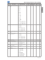
P0263 DI1 Function 0 = Not Used
1 = Run/Stop
2 = General Enable
3 = Fast Stop
4 = FWD/REV
5 = LOC/REM
6 = JOG
7 = SoftPLC
8 = Ramp 2
9 = Speed/Torque
10 = JOG+
11 = JOG-
12 = No External Alarm
13 = No External Fault
14 = Reset
15 = Flying Start Disabling
16 = DC Link Regulator
17 = Program. Disabling
18 = Load User 1
19 = Load User 2
20 = Application Function 1
21 = Application Function 2
12 = Application Function 3
23 = Application Function 4
24 = Application Function 5
25 = Application Function 6
26 = Application Function 7
27 = Application Function 8
28 = Application Function 9
29 = Application Function
10
30 = Application Function
11
31 = Application Function
12
1 cfg I/O 13-10
P0264 DI2 Function Refer to the P0263 options 4 cfg I/O 13-10
P0265 DI3 Function Refer to the P0263 options 0 cfg I/O 13-10
P0266 DI4 Function Refer to the P0263 options 0 cfg I/O 13-10
P0267 DI5 Function Refer to the P0263 options 6 cfg I/O 13-10
P0268 DI6 Function Refer to the P0263 options 8 cfg I/O 13-10
P0269 DI7 Function Refer to the P0263 options 0 cfg I/O 13-10
P0270 DI8 Function Refer to the P0263 options 0 cfg I/O 13-10

CFW700 | 11
Quick Parameter Reference, Faults and Alarms
English
Param. Description Adjustable Range
Factory
Setting
User
Setting
Prop. Groups Pag.
P0275 DO1 Function (RL1) 0 = Not Used
1 = N* > Nx
2 = N > Nx
3 = N < Ny
4 = N = N*
5 = Zero Speed
6 = Is > Ix
7 = Is < Ix
8 = Torque > Tx
9 = Torque < Tx
10 = Remote
11 = Run
12 = Ready
13 = No Fault
14 = No F0070
15 = No F0071
16 = No F0006/21/22
17 = No F0051
18 = No F0072
19 = 4-20 mA OK
20 = P0695 Value
21 = Forward
22 = Ride-Through
23 = Pre-Charge OK
24 = Fault
25 = Enabled Time > Hx
26 = SoftPLC
27 = N > Nx / Nt > Nx
28 = F > Fx (1)
29 = F > Fx (2)
30 = STO
31 = No F0160
32 = No Alarm
33 = No Fault/Alarm
34 = Application Function 1
35 = Application Function 2
36 = Application Function 3
37 = Application Function 4
38 = Application Function 5
39 = Application Function 6
40 = Application Function 7
41 = Application Function 8
42 = Self-tuning
13 cfg I/O 13-16
P0276 DO2 Function Refer to the P0275 options 2 cfg I/O 13-16
P0277 DO3 Function Refer to the P0275 options 1 cfg I/O 13-16
P0278 DO4 Function Refer to the P0275 options 0 cfg I/O 13-16
P0279 DO5 Function Refer to the P0275 options 0 cfg I/O 13-16
P0281 Fx Frequency 0.0 to 300.0 Hz 4.0 Hz 13-20
P0282 Fx Hysteresis 0.0 to 15.0 Hz 2.0 Hz 13-21
P0287 Nx/Ny Hysteresis 0 to 900 rpm 18 (15) rpm 13-21
P0288 Nx Speed 0 to 18000 rpm 120 (100)
rpm
13-21
P0289 Ny Speed 0 to 18000 rpm 1800 (1500)
rpm
13-21
P0290 Ix Current 0 to 2 x I
nom-ND
1.0 x I
nom-ND
13-21
P0291 Zero Speed 0 to 18000 rpm 18 (15) rpm 13-22
P0292 N = N* Band 0 to 18000 rpm 18 (15) rpm 13-22
P0293 Tx Torque 0 to 200 % 100 % 13-22
P0294 Hx Time 0 to 6553 h 4320 h 13-22

12 | CFW700
Quick Parameter Reference, Faults and Alarms
English
Param. Description Adjustable Range
Factory
Setting
User
Setting
Prop. Groups Pag.
P0295 ND/HD VFD Rated Current 0 = 2 A / 2 A
1 = 3.6 A / 3.6 A
2 = 5 A / 5 A
3 = 6 A / 5 A
4 = 7 A / 5.5 A
5 = 7 A / 7 A
6 = 10 A / 8 A
7 = 10 A / 10 A
8 = 13 A / 11 A
9 = 13.5 A / 11 A
10 = 16 A / 13 A
11 = 17 A / 13.5 A
12 = 24 A / 19 A
13 = 24 A / 20 A
14 = 28 A / 24 A
15 = 31 A / 25 A
16 = 33.5 A / 28 A
17 = 38 A / 33 A
18 = 45 A / 36 A
19 = 45 A / 38 A
20 = 54 A / 45 A
21 = 58.5 A / 47 A
22 = 70 A / 56 A
23 = 70.5 A / 61 A
24 = 86 A / 70 A
25 = 88 A / 73 A
26 = 105 A / 86 A
27 = 105 A / 88 A
28 = 142 A / 115 A
29 = 180 A / 142 A
30 = 211 A / 180 A
31 = 2.9 A / 2.7 A
32 = 4.2 A / 3.8 A
33 = 7 A / 6.5 A
34 = 10 A / 9 A
35 = 12 A / 10 A
36 = 17 A / 17 A
37 = 22 A / 19 A
38 = 27 A / 22 A
39 = 32 A / 27 A
40 = 44 A / 36 A
41 = 53 A / 44 A
42 = 63 A / 53 A
43 = 80 A / 66 A
44 = 107 A / 90 A
45 = 125 A / 107 A
46 = 150 A / 122 A
ro READ 6-6
P0296 Line Rated Voltage 0 = 200 / 240 V
1 = 380 V
2 = 400 / 415 V
3 = 440 / 460 V
4 = 480 V
5 = 500 / 525 V
6 = 550 / 575 V
7 = 600 V
According
to the
inverter
model
cfg 6-7
P0297 Switching Frequency 0 = 1.25 kHz
1 = 2.5 kHz
2 = 5.0 kHz
3 = 10.0 kHz
4 = 2.0 kHz
According
to the
inverter
model
cfg 6-7
P0298 Application 0 = Normal Duty (ND)
1 = Heavy Duty (HD)
0 cfg 6-8

CFW700 | 13
Quick Parameter Reference, Faults and Alarms
English
Param. Description Adjustable Range
Factory
Setting
User
Setting
Prop. Groups Pag.
P0299 Starting DC-Braking Time 0.0 to 15.0 s 0.0 s V/f,
VVW,
Sless
12-16
P0300 Stopping DC-Braking Time 0.0 to 15.0 s 0.0 s V/f,
VVW,
Sless
12-16
P0301 DC-Braking Speed 0 to 450 rpm 30 rpm V/f,
VVW,
Sless
12-18
P0302 DC-Braking Voltage 0.0 to 10.0 % 2.0 % V/f,
VVW
12-18
P0303 Skip Speed 1 0 to 18000 rpm 600 rpm 12-19
P0304 Skip Speed 2 0 to 18000 rpm 900 rpm 12-19
P0305 Skip Speed 3 0 to 18000 rpm 1200 rpm 12-19
P0306 Skip Band 0 to 750 rpm 0 rpm 12-19
P0308 Serial Address 1 to 247 1 NET 17-1
P0310 Serial Baud Rate 0 = 9600 bits/s
1 = 19200 bits/s
2 = 38400 bits/s
3 = 57600 bits/s
1 NET 17-1
P0311 Serial Byte Configuration 0 = 8 bits, no, 1
1 = 8 bits, even, 1
2 = 8 bits, odd, 1
3 = 8 bits, no, 2
4 = 8 bits, even, 2
5 = 8 bits, odd, 2
1 NET 17-1
P0313 Communication Error
Action
0 = Off
1 = Ramp Stop
2 = General Disable
3 = Goes to LOC
4 = LOC Keeping Enabled
5 = Causes Fault
1 NET 17-3
P0314 Serial Watchdog 0.0 to 999.0 s 0.0 s NET 17-1
P0316 Serial Interface Status 0 = Off
1 = On
2 = Watchdog Error
ro NET 17-1
P0317 Oriented Start-up 0 = No
1 = Yes
0 cfg STARTUP 7-2
P0318 Copy Function MMF 0 = Off
1 = VFD → MMF
2 = MMF → VFD
3 = VFD Synchronization
→ MMF
4 = MMF Format
5 = SoftPLC Program Copy
6= SoftPLC Program Save
0 cfg 7-2
P0320 FlyStart/Ride-Through 0 = Off
1 = Flying Start
2 = FS / RT
3 = Ride-Through
0 cfg 12-8
P0321 DC Link Power Loss 178 to 770 V 505 V Vector 12-14
P0322 DC Link Ride-Through 178 to 770 V 490 V Vector 12-14
P0323 DC Link Power Back 178 to 770 V 535 V Vector 12-14
P0325 Ride-Through P Gain 0.0 to 63.9 22.8 Vector 12-15
P0326 Ride-Through I Gain 0.000 to 9.999 0.128 Vector 12-15
P0327 FS I/f Current Ramp 0.000 to 1.000 s 0.070 Sless 12-10
P0328 Flying Start Filter 0.000 to 1.000 s 0.085 Sless 12-10
P0329 FS I/f Frequency Ramp 2.0 to 50.0 20.0 Sless 12-10

14 | CFW700
Quick Parameter Reference, Faults and Alarms
English
Param. Description Adjustable Range
Factory
Setting
User
Setting
Prop. Groups Pag.
P0331 Voltage Ramp 0.2 to 60.0 s 2.0 s V/f,
VVW
12-12
P0332 Dead Time 0.1 to 10.0 s 1.0 s V/f,
VVW
12-12
P0340 Auto-Reset Time 0 to 255 s 0 s 15-8
P0343 Ground Fault Configuration 0 = Off
1 = On
1 cfg 15-8
P0344 Current Limit Configuration 0 = Hold
1 = Decel.
1 cfg, V/f,
VVW
9-7
P0348 Motor Overload
Configuration
0 = Off
1 = Fault/Alarm
2 = Fault
3 = Alarm
1 cfg 15-8
P0349 I x t Alarm Level 70 to 100 % 85 % cfg 15-9
P0350 IGBT Overload
Configuration
0 = F, w/ SF rd.
1 = F/A, w/ SF rd.
2 = F, no SF rd.
3 = F/A, no SF rd.
1 cfg 15-9
P0351 Motor Overtemperature
Config.
0 = Off
1 = Fault/Alarm
2 = Fault
3 = Alarm
1 cfg 15-10
P0352 Fan Control Configuration 0 = HS-OFF, Int-OFF
1 = HS-ON, Int-ON
2 = HS-CT, Int-CT
3 = HS-CT, Int-OFF
4 = HS-CT, Int-ON
5 = HS-ON, Int-OFF
6 = HS-ON, Int-CT
7 = HS-OFF, Int-ON
8 = HS-OFF, Int-CT
9 = HS-CT, Int -CT *
10 = HS-CT, Int -OFF *
11 = HS-CT, Int -ON *
12 = HS-ON, Int -CT *
13 = HS-OFF, Int -CT *
2 cfg 15-10
P0353 IGBTs/Air Overtemp.
Config.
0 = HS-F/A, Air-F/A
1 = HS-F/A, Air-F
2 = HS-F, Air-F/A
3 = HS-F, Air-F
4 = HS-F/A, Air-F/A *
5 = HS-F/A, Air-F *
6 = HS-F, Air-F/A *
7 = HS-F, Air-F *
0 cfg 15-11
P0354 Fan Speed Configuration 0 = Inactive
1 = Fault
1 cfg 15-12
P0355 Config. of Fault F0185 0 = Off
1 = On
1 cfg 15-12
P0356 Dead Time Compensation 0 = Inactive
1 = Active
1 cfg 15-13
P0357 Line Phase Loss Time 0 to 60 s 3 s 15-13
P0358 Encoder Fault Config. 0 = Off
1 = F0067 ON
2 = F0065, F0066 ON
3 = All ON
3 cfg, Enc 15-13
P0360 Speed Hysteresis 0.0 to 100.0 % 10.0 % Vector 11-23
P0361 Time with Speed different
from Reference
0.0 to 999.0 s 0.0 s Vector 11-24
P0372 Sless DC Braking Current 0.0 to 90.0 % 40.0 % Sless 12-18

CFW700 | 15
Quick Parameter Reference, Faults and Alarms
English
Param. Description Adjustable Range
Factory
Setting
User
Setting
Prop. Groups Pag.
P0397 Regen. Slip Compensation 0 = Off
1 = On
1 cfg,
VVW
10-3
P0398 Motor Service Factor 1.00 to 1.50 1.00 cfg MOTOR 11-9
P0399 Motor Rated Efficiency 50.0 to 99.9 % 67.0 % cfg,
VVW
MOTOR 10-3
P0400 Motor Rated Voltage 0 to 600 V 440 V cfg MOTOR 11-9
P0401 Motor Rated Current 0 to 1.3 x I
nom-ND
1.0 x I
nom-ND
cfg MOTOR 11-9
P0402 Motor Rated Speed 0 to 18000 rpm 1750 (1458)
rpm
cfg MOTOR 11-10
P0403 Motor Rated Frequency 0 to 300 Hz 60 (50) Hz cfg MOTOR 11-10
P0404 Motor Rated Power 0 = 0.33 HP 0.25 kW
1 = 0.5 HP 0.37 kW
2 = 0.75 HP 0.55 kW
3 = 1 HP 0.75 kW
4 = 1.5 HP 1.1 kW
5 = 2 HP 1.5 kW
6 = 3 HP 2.2 kW
7 = 4 HP 3 kW
8 = 5 HP 3.7 kW
9 = 5.5 HP 4 kW
10 = 6 HP 4.5 kW
11 = 7.5 HP 5.5 kW
12 = 10 HP 7.5 kW
13 = 12.5 HP 9 kW
14 = 15 HP 11 kW
15 = 20 HP 15 kW
16 = 25 HP 18.5 kW
17 = 30 HP 22 kW
18 = 40 HP 30 kW
19 = 50 HP 37 kW
20 = 60 HP 45 kW
21 = 75 HP 55 kW
22 = 100 HP 75 kW
23 = 125 HP 90 kW
24 = 150 HP 110 kW
25 = 175 HP 130 kW
Motor
max-ND
cfg MOTOR 11-10
P0405 Encoder Pulse Number 100 to 9999 ppr 1024 ppr cfg MOTOR 11-11
P0406 Motor Ventilation 0 = Self-Ventilated
1 = Separated Ventilation
2 = Optimal Flux
3 = Extended Protection
0 cfg MOTOR 11-11
P0407 Motor Rated Power Factor 0.50 to 0.99 0.68 cfg,
VVW
MOTOR 9-13
10-4
P0408 Run Self-Tuning
0 = No
1 = No Rotation
2 = Run for I
m
3 = Run for T
m
4 = Estimate T
m
0 cfg,
VVW,
Vector
MOTOR 11-18
P0409 Stator Resistance 0.000 to 9.999 ohm 0.000 ohm cfg,
VVW,
Vector
MOTOR 11-20
P0410 Magnetization Current 0 to 1.25 x I
nom-ND
I
nom-ND
MOTOR 11-20
P0411 Leakage Inductance 0.00 to 99.99 mH 0.00 mH cfg,
Vector
MOTOR 11-20
P0412
T
r
Time Constant
0.000 to 9.999 s 0.000 s Vector MOTOR 11-21
P0413
T
m
Time Constant
0.00 to 99.99 s 0.00 s Vector MOTOR 11-21

16 | CFW700
Quick Parameter Reference, Faults and Alarms
English
Param. Description Adjustable Range
Factory
Setting
User
Setting
Prop. Groups Pag.
P0510
Ind. 1 Engineering Unit
0 = None
1 = V
2 = A
3 = rpm
4 = s
5 = ms
6 = N
7 = m
8 = Nm
9 = mA
10 = %
11 = °C
12 = CV
13 = Hz
14 = HP
15 = h
16 = W
17 = kW
18 = kWh
19 = H
0 HMI 5-6
P0511
Ind. Decimal Point 1
0 = wxyz
1 = wxy.z
2 = wx.yz
3 = w.xyz
1 HMI 5-6
P0512
Ind. Eng. Unit 2
See options in P0510 11 HMI 5-7
P0513
Ind. Decimal Point 2 0 = wxyz
1 = wxy.z
2 = wx.yz
3 = w.xyz
1 HMI 5-7
P0514
Ind. Eng. Unit 3 See options in P0510 10
HMI 5-8
P0515
Ind. Decimal Point 3 0 = wxyz
1 = wxy.z
2 = wx.yz
3 = w.xyz
1 HMI 5-8
P0516
Ind. Eng. Unit 4 See options in P0510 13
HMI 5-9
P0517
Ind. Decimal Point 4 0 = wxyz
1 = wxy.z
2 = wx.yz
3 = w.xyz
1 HMI 5-9
P0588
Maximum Torque Level
0 to 85 % 0 % cfg, V/f 9-13
P0589
Level of Minimum Applied
Voltage
40 to 80 % 40 % cfg, V/f 9-13
P0590
Minimum Speed Level
0 to 18000 rpm 600 (525)
rpm
cfg, V/f 9-14
P0591
Hysteresis for the
Maximum Torque Level
0 to 30 % 10 % cfg, V/f 9-14
P0613 Firmware Revision -32768 to 32767 0 ro 16-8
P0614 Revision of the PLD -32768 to 32767 0 ro 16-8

CFW700 | 17
Quick Parameter Reference, Faults and Alarms
English
Param. Description Adjustable Range
Factory
Setting
User
Setting
Prop. Groups Pag.
P0680 Status Word Bit 0 = Reserved
Bit 1 = Run command
Bit 2 = Reserved
Bit 3 = Reserved
Bit 4 = Fast Stop
Bit 5 = 2
nd
Ramp
Bit 6 = Configuration Mode
Bit 7 = Alarm Condition
Bit 8 = Running
Bit 9 = General Enabling
Bit 10 = Forward
Bit 11 = JOG
Bit 12 = Remote
Bit 13 = Undervoltage
Bit 14 = Reserved
Bit 15 = Fault Condition
ro NET 17-3
P0681 Motor Speed in 13 Bits -32768 to 32767 ro NET 17-3
P0682 Serial Control Word Bit 0 = Ramp Enable
Bit 1 = General Enable
Bit 2 = Run Forward
Bit 3 = JOG
Bit 4 = Remote
Bit 5 = 2
nd
Ramp
Bit 6 = Fast Stop
Bit 7 = Fault Reset
Bit 8 to 15 = Reserved
ro NET 17-1
P0683 Serial Speed Reference -32768 to 32767 ro NET 17-1
P0684 CO/DN/DP Control Word Refer to the P0682 options ro NET 17-1
P0685 CO/DN/DP Speed
Reference
- 32768 to 32767 ro NET 17-1
P0692 Operating Mode States 0 to 65535 0 ro 16-8
P0695 Settings for the Digital
Outputs
Bit 0 = DO1
Bit 1 = DO2
Bit 2 = DO3
Bit 3 = DO4
Bit 4 = DO5
Bit 4 NET 17-3
P0696 Value 1 for Analog Outputs - 32768 to 32767 0 NET 17-3
P0697 Value 2 for Analog Outputs - 32768 to 32767 0 NET 17-3
P0700 CAN Protocol 1 = CANopen
2 = DeviceNet
2 NET 17-1
P0701 CAN Address 0 to 127 63 NET 17-1
P0702 CAN Baud Rate 0 = 1 Mbps/Auto
1 = Reserved/Auto
2 = 500 Kbps
3 = 250 Kbps
4 = 125 Kbps
5 = 100 Kbps/Auto
6 = 50 Kbps/Auto
7 = 20 Kbps/Auto
8 = 10 Kbps/Auto
0 NET 17-1
P0703 Bus Off Reset 0 = Manual
1 = Automatic
1 NET 17-1
P0705 CAN Controller Status 0 = Disabled
1 = Auto-baud
2 = CAN Enabled
3 = Warning
4 = Error Passive
5 = Bus Off
6 = No Bus Power
ro NET 17-1
P0706 Received CAN Telegrams 0 to 65535 ro NET 17-1

18 | CFW700
Quick Parameter Reference, Faults and Alarms
English
Param. Description Adjustable Range
Factory
Setting
User
Setting
Prop. Groups Pag.
P0707 Transmitted CAN
Telegrams
0 to 65535 ro NET 17-1
P0708 Bus Off Counter 0 to 65535 ro NET 17-1
P0709 Lost CAN Messages 0 to 65535 ro NET 17-1
P0710 DeviceNet I/O Instances 0 = ODVA Basic 2W
1 = ODVA Extended 2W
2 = Manuf. Spec. 2W
3 = Manuf. Spec. 3W
4 = Manuf. Spec. 4W
5 = Manuf. Spec. 5W
6 = Manuf. Spec. 6W
0 NET 17-1
P0711 DeviceNet Reading Word
# 3
0 to 1199 0 NET 17-2
P0712 DeviceNet Reading Word
# 4
0 to 1199 0 NET 17-2
P0713 DeviceNet Reading Word
# 5
0 to 1199 0 NET 17-2
P0714 DeviceNet Reading Word
# 6
0 to 1199 0 NET 17-2
P0715 DeviceNet Writing Word
# 3
0 to 1199 0 NET 17-2
P0716 DeviceNet Writing Word
# 4
0 to 1199 0 NET 17-2
P0717 DeviceNet Writing Word
# 5
0 to 1199 0 NET 17-2
P0718 DeviceNet Writing Word
# 6
0 to 1199 0 NET 17-2
P0719 DeviceNet Network Status 0 = Offline
1 = Online, Not Connected
2 = Online, Connected
3 = Timed-out Connection
4 = Connection Failure
5 = Auto-Baud
ro NET 17-2
P0720 DeviceNet Master Status 0 = Run
1 = Idle
ro NET 17-2
P0721 CANopen Com. Status 0 = Disabled
1 = Reserved
2 = Com. Enabled
3 = Error Control Enabled
4 = Guarding Error
5 = Heartbeat Error
ro NET 17-2
P0722 CANopen Node Status 0 = Disabled
1 = Initialization
2 = Stopped
3 = Operational
4 = Preoperational
ro NET 17-2
P0740 Profibus Communication
Status
0 = Inactive
1 = Access Error
2 = Offline
3 = Configuration Error
4 = Parameterization Error
5 = Clear Mode
6 = Online
ro NET 17-2
P0741 Profibus Data Profile 0 = PROFIdrive
1 = Manufacturer
1 NET 17-2
P0742 Profibus Reading # 3 0 to 1199 0 NET 17-2
P0743 Profibus Reading # 4 0 to 1199 0 NET 17-2
P0744 Profibus Reading # 5 0 to 1199 0 NET 17-2
P0745 Profibus Reading # 6 0 to 1199 0 NET 17-2
P0746 Profibus Reading # 7 0 to 1199 0 NET 17-2

CFW700 | 19
Quick Parameter Reference, Faults and Alarms
English
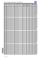
Param. Description Adjustable Range
Factory
Setting
User
Setting
Prop. Groups Pag.
P0747 Profibus Reading # 8 0 to 1199 0 NET 17-2
P0748 Profibus Reading # 9 0 to 1199 0 NET 17-2
P0749 Profibus Reading # 10 0 to 1199 0 NET 17-2
P0750 Profibus Writing # 3 0 to 1199 0 NET 17-3
P0751 Profibus Writing # 4 0 to 1199 0 NET 17-3
P0752 Profibus Writing # 5 0 to 1199 0 NET 17-3
P0753 Profibus Writing # 6 0 to 1199 0 NET 17-3
P0754 Profibus Writing # 7 0 to 1199 0 NET 17-3
P0755 Profibus Writing # 8 0 to 1199 0 NET 17-3
P0756 Profibus Writing # 9 0 to 1199 0 NET 17-3
P0757 Profibus Writing # 10 0 to 1199 0 NET 17-3
P0918 Profibus Address 1 to 126 1 NET 17-3
P0922 Profibus Telegram
Selection
1 = Standard Telegram 1
2 = Telegram 100
3 = Telegram 101
4 = Telegram 102
5 = Telegram 103
6 = Telegram 104
7 = Telegram 105
8 = Telegram 106
9 = Telegram 107
1 NET 17-3
P0944 Fault Counter 0 to 65535 ro NET 17-3
P0947 Fault Number 0 to 65535 ro NET 17-3
P0963 Profibus Baud Rate 0 = 9.6 kbit/s
1 = 19.2 kbit/s
2 = 93.75kbit/s
3 = 187.5 kbit/s
4 = 500 kbit/s
5 = Not detected
6 = 1500 kbit/s
7 = 3000 kbit/s
8 = 6000 kbit/s
9 = 12000 kbit/s
10 = Reserved
11 = 45.45 kbit/s
ro NET 17-3
P0964 Drive Identification 0 to 65535 ro NET 17-3
P0965 Profile Identification 0 to 65535 ro NET 17-3
P0967 Control Word 1 0000h to FFFFh 0000h ro NET 17-3
P0968 Status Word 1 0000h to FFFFh 0000h ro NET 17-3
P1000 SoftPLC Status 0 = No Applicative
1 = Installing App.
2 = Incompatible App.
3 = Stopped Applicative
4 = Applicative Running
ro SPLC,
READ
18-1
P1001 SoftPLC Command 0 = Stop Applicative
1 = Run Applicative
2 = Delete Applicative
0 SPLC 18-1
P1002 Scan Cycle Time 0.0 to 999.9 ms ro READ,
SPLC
18-1
P1003 Applicative Selection 0 = User
1 = PID Controller
2 = EP
3 = Multispeed
4 = 3-Wire Start/Stop
5 = FWD Run/ REV Run
6 = Special Function Set
0 cfg SPLC 18-2
P1008 Lag Error -9999 to 9999 ro, Enc SPLC 18-2
P1009 Position Gain 0 to 9999 10 Enc SPLC 18-3
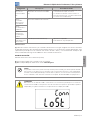
A página está carregando...
A página está carregando...
A página está carregando...
A página está carregando...
A página está carregando...
A página está carregando...
A página está carregando...
A página está carregando...
A página está carregando...
A página está carregando...
A página está carregando...
A página está carregando...
A página está carregando...
A página está carregando...
A página está carregando...
A página está carregando...
A página está carregando...
A página está carregando...
A página está carregando...
A página está carregando...
A página está carregando...
A página está carregando...
A página está carregando...
A página está carregando...
A página está carregando...
A página está carregando...
A página está carregando...
A página está carregando...
A página está carregando...
A página está carregando...
A página está carregando...
A página está carregando...
A página está carregando...
A página está carregando...
A página está carregando...
A página está carregando...
A página está carregando...
A página está carregando...
A página está carregando...
A página está carregando...
A página está carregando...
A página está carregando...
A página está carregando...
A página está carregando...
A página está carregando...
A página está carregando...
A página está carregando...
A página está carregando...
A página está carregando...
A página está carregando...
A página está carregando...
A página está carregando...
A página está carregando...
A página está carregando...
A página está carregando...
A página está carregando...
A página está carregando...
A página está carregando...
A página está carregando...
A página está carregando...
A página está carregando...
A página está carregando...
A página está carregando...
A página está carregando...
A página está carregando...
A página está carregando...
-
 1
1
-
 2
2
-
 3
3
-
 4
4
-
 5
5
-
 6
6
-
 7
7
-
 8
8
-
 9
9
-
 10
10
-
 11
11
-
 12
12
-
 13
13
-
 14
14
-
 15
15
-
 16
16
-
 17
17
-
 18
18
-
 19
19
-
 20
20
-
 21
21
-
 22
22
-
 23
23
-
 24
24
-
 25
25
-
 26
26
-
 27
27
-
 28
28
-
 29
29
-
 30
30
-
 31
31
-
 32
32
-
 33
33
-
 34
34
-
 35
35
-
 36
36
-
 37
37
-
 38
38
-
 39
39
-
 40
40
-
 41
41
-
 42
42
-
 43
43
-
 44
44
-
 45
45
-
 46
46
-
 47
47
-
 48
48
-
 49
49
-
 50
50
-
 51
51
-
 52
52
-
 53
53
-
 54
54
-
 55
55
-
 56
56
-
 57
57
-
 58
58
-
 59
59
-
 60
60
-
 61
61
-
 62
62
-
 63
63
-
 64
64
-
 65
65
-
 66
66
-
 67
67
-
 68
68
-
 69
69
-
 70
70
-
 71
71
-
 72
72
-
 73
73
-
 74
74
-
 75
75
-
 76
76
-
 77
77
-
 78
78
-
 79
79
-
 80
80
-
 81
81
-
 82
82
-
 83
83
-
 84
84
-
 85
85
-
 86
86


