SPECIFICATIONS ISTRUZIONI DI INSTALLAZIONE E TARATURA
ID003
INSTALLAZIONE
3) Installazione temporanea con basi
magnetiche: seguire le istruzioni fornite con
la base magnetica ricordandosi che si tratta di
un’installazione TEMPORANEA.
2) Installazione con attacchi speciali:
seguire la stessa procedura del punto 1.
TARATURA
B) Collegamenti : Po sizionare il cavo
dell’antenna accorciandolo in base alle
necessità, quindi montare il connettore PL
259 maschio per la connessione all’apparato
CB.
1) Installazione con foratura della
carrozzeria:
A) Foratura: Praticare il foro del diametro
ri c hie s to n e lla p osi z ion e d esi der a ta
(consigliato a centro tetto). Togliere la vernice
nella parte interna della carrozzeria per
garantire un buon contatto elettrico di massa.
C) Verifiche elettriche: Assenza di corto
circuito tra spina centrale e ghiera di massa del
co nn e tt o re , co n ti nu i tà e le t tr ic a d el
conduttore centrale da un’estremità all’altra
del cavo, continuità elettrica calza cavo dalla
ghiera lato connettore al contatto di massa
lato connettore d’antenna.
D) Installazione: Completare il montaggio
dell’antenna serrando adeguatamente viti e
bulloni.
N.B.: Si consiglia di testare il cavo lasciandolo
scollegato dall’antenna poiché alcune
antenne sono elettricamente in corto circuito
e non è possibile eseguire il test ad
installazione completata.
E) Consiglio: a montaggio terminato e PRIMA
di connettere il trasmettitore, si consiglia di
verificare la continuità elettrica tra la ghiera del
connettore PL 259 e un punto di massa della
carrozzeria.
A) Recarsi in spazio aperto ad almeno 50 metri
Le antenne sono pre-tarate in fabbrica
pertanto nella maggior parte dei casi non
necessitano di taratura. In caso si renda
necessaria una leggera taratura consigliamo
di seguire la procedura riportata di seguito.
B) Collegare un SWR-meter (ROS-metro) tra il
connettore dell’antenna e il trasmettitore CB.
Seguire le istruzioni del ROS-metro per il
corretto utilizzo dell’apparato.
G) Se il valore di SWR è più basso su CH-1
rispetto a CH-40, la vostra antenna é
elettricamente “lunga”, quindi accorciare lo
stilo di circa 10mm alla volta fino ad ottenere
gli stessi valori di SWR sia su CH-1 che su CH-40.
o più da oggetti metallici quali cancelli,
lampioni, edifici o tralicci.
C) La seguente procedura si applica per la
taratura dei 40 canali omologati per banda CB
compresi nel range di frequenza da CH-1 =
26.965 MHz a CH-40 = 27.405 MHz con
CH-19 =27.185MHz in centro banda.
Selezionare il CH-1 sul trasmettitore CB ed
effettuare la misura di SWR annotandone il
valore. Trasmettere sempre per pochi
secondi perché se l’ SWR fosse molto alto
si potrebbe danneggiare il trasmettitore.
F) Se i valori di SWR sono uguali per CH-1 e CH-
40 e il valore minimo si ha su CH-19, la vostra
antenna non necessita di alcuna taratura.
D) Ripetere l’operazione anche per il CH-19 e il
CH-40.
E) Se tutti e tre i valori di SWR sono molto alti
(maggiori del valore 3) o tendenti a infinito,
probabilmente è presente un corto circuito nel
cablaggio oppure l’antenna è guasta. Per
e v i t a r e d i d a n n e g g i a r e i l v o s t r o
trasmettitore CB NON utilizzarlo finché il
problema non sarà risolto.
H) Se il valore di SWR è più basso su CH-40
rispetto a CH-1, la vostra antenna é
elettricamente “corta”, quindi allungare lo
stilo sfilandolo di 10mm alla volta fino ad
ottenere gli stessi valori di SWR sia su CH-1 che
su CH-40.
HI-QUALITY ANTENNAS MADE IN ITALY
antenne
SIRIO
S
250 Watts (CW) short time
1400 mm, 4.6 ft
35 Watts (CW) continuous,
³ 1850 KHz (170 channel)
SUPER CARBONIUM 27
Thecnical Data
Type
Impedance
SWR @ freq. res.
Polarization
Bandwidth @ SWR 2£
Frequency Range
Weight (approx.)
Standard mount
Height (approx.)
Max Power
Cable length / type
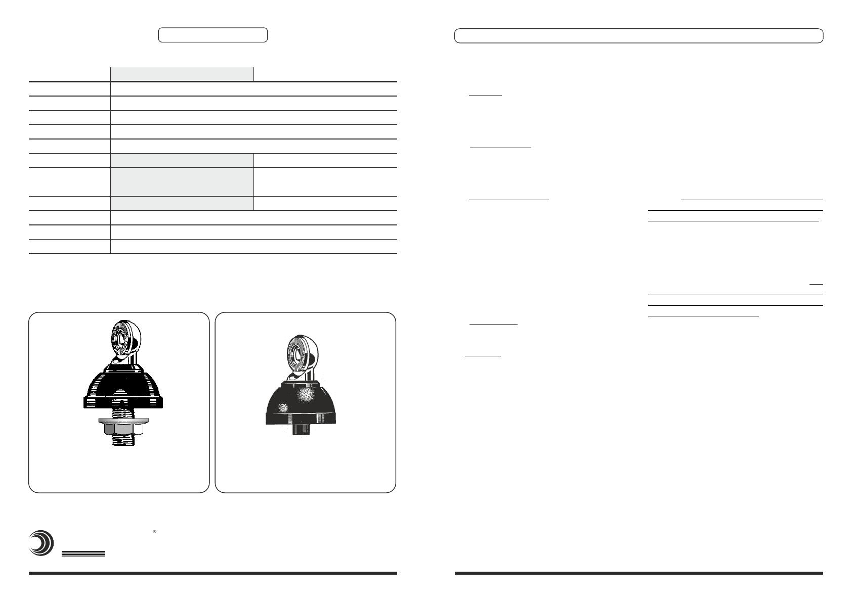
"N" mount, hole 12.5mm, 1/2 inÆ
4 m, 13 ft / RG 58
CB Base Loaded
480 gr, 1.05 lb
£ 1.2
50 W
Linear Vertical
27 ... 28.5 MHz
CARBONIUM 27
³ 1620 KHz (140 channel)
25 Watts (CW) continuous,
150 Watts (CW) short time
1130 mm, 3.7 ft
Alternative: “NE” mount
Mountiing Hole
10 mm, 0.4 inÆ
Standard: “N” mount
Mountiing Hole:
12.5 mm, 1/2 inÆ

