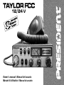
PRESIDENT Taylor FCC Manual do proprietário
- Tipo
- Manual do proprietário

Owner’s manual / Manual del usuario
Manuel d’utilisation / Manual do usuário
12/24 V

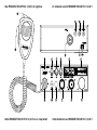
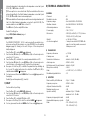
Un vistazo a vuestro PRESIDENT TAYLOR FCC 12/24 VYour PRESIDENT TAYLOR FCC 12/24 V at a glance
Votre PRESIDENT TAYLOR FCC 12/24 V en un coup d'œil Uma olhada no seu PRESIDENT TAYLOR FCC 12/24 V

3
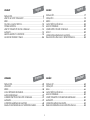
SUMARIO
INSTALACIÓN ......................................................................................... 17
UTILIZACIÓN ........................................................................................... 19
MENÚS .................................................................................................... 22
CARACTERÍSTICAS TÉCNICAS ............................................................... 24
GUÍA DE PROBLEMAS ............................................................................ 25
COMO EMITIR O RECIBIR UN MENSAJE ............................................... 25
LÉXICO .................................................................................................... 25
CONDICIONES GENERALES DE GARANTÍA ......................................... 27
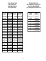
TABLAS DE FRECUENCIAS CB Y METEOROLÓGICAS .......................... 54
SOMMAIRE
INSTALLATION ..........................................................................................29
UTILISATION .............................................................................................. 31
MENUS .....................................................................................................34
CARACTÉRISTIQUES TECHNIQUES ..........................................................36
GUIDE DE DÉPANNAGE .......................................................................... 37
COMMENT ÉMETTRE OU RECEVOIR UN MESSAGE ..............................37
GLOSSAIRE ..............................................................................................37
CONDITIONS GÉNÉRALES DE GARANTIE .............................................40
TABLEAUX DES FRÉQUENCES CB ET MÉTÉOROLOGIQUES ................... 54
Français
Español
SUMMARY
INSTALLATION ........................................................................................... 5
HOW TO USE YOUR TRANSCEIVER .......................................................... 7
MENU ........................................................................................................ 9
TECHNICAL CHARACTERISTICS ............................................................. 12
TROUBLE SHOOTING .............................................................................. 13
HOW TO TRANSMIT OR RECEIVE A MESSAGE ..................................... 13
GLOSSARY .............................................................................................. 13
GENERAL WARRANTY CONDITIONS .................................................... 15
CB AND WX FREQUENCY TABLES ........................................................ 54
English
Português
SUMÁRIO
INSTALAÇÃO .......................................................................................... 42
UTILIZAÇÃO ............................................................................................ 44
MENUS .....................................................................................................................46
CARACTERÍSTICAS TÉCNICAS ............................................................... 49
GUIA DE PROBLEMAS ............................................................................ 50
COMO TRANSMITIR OU RECEBER UMA MENSAGEM .......................... 50
GLOSSÁRIO ............................................................................................ 50
CONDIÇÕES GERAIS DE GARANTIA .................................................... 53
TABELAS DE FREQUÊNCIAS CB E METEOROLÓGICAS ........................ 54

4
The guarantee of this transceiver is valid only in the country of purchase.
WARNING !
Before using, be careful never to transmit without
first having connected the antenna (connection
“B” situated on the back panel of the equip-
ment) or without having set the SWR (Standing
Wave Ratio) ! Failure to do so may result in
destruction of the power amplifier, which is not
covered by the guarantee.
English
WARNING: This product can expose you to chemicals including Lead, which is known to the State of California to cause cancer and birth defects or other repro-
ductive harm. For more information go to www.P65Warnings.ca.gov.
AVERTISSEMENT : Ce produit peut vous exposer à des agents chimiques, y compris le plomb, identifiés par l’État de Californie comme pouvant causer le cancer et
des malformations congénitales ou autres effets nocifs sur la reproduction. Pour de plus amples informations, prière de consulter le site www.P65Warnings.ca.gov.

5
Welcome to the world of the new generation of CB radios. The new PRESIDENT
range gives you access to top performance transceiver equipment. With the
use of up-to-date technology, which guarantees unprecedented quality, your
PRESIDENT TAYLOR FCC 12/24 V is a new step in personal communication and
is the surest choice for the most demanding of professional CB radio users. To
ensure that you make the most of all its capacities, we advise you to read care-
fully this manual before installing and using your PRESIDENT TAYLOR FCC 12/24 V.
A) INSTALLATION
1) WHERE AND HOW TO MOUNT YOUR MOBILE CB RADIO
a) You should choose a well ventilated place most appropriate setting from
a simple and practical point of view.
b) Your CB radio should not interfere with the driver or the passengers.
c) Remember to provide for the passing and protection of different wires
(e.g. power, antenna, accessory cabling) so that they do not in any way
interfere with the driving of the vehicle.
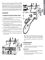
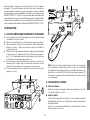
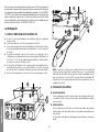
d) To install your equipment, use the cradle (1) and the self-tapping screws
(2) provided (drilling diameter 1.126” / 3.2 mm). Take care not to damage
the vehicle’s electrical system while drilling the dash board.
e) Do not forget to insert the rubber joints (3) between the CB and its support
as these have a shock-absorbing effect which permits gentle orientation
and tightening of the set.
f) Choose where to place the microphone support and remember that the
microphone cord must stretch to the driver without interfering with the
controls of the vehicle.
- N.B.: As the transceiver has a frontal microphone socket, it can be set into
the dash board. In this case, you will need to add an external loud speaker
to improve the sound quality of communications (connector EXT SP situated
on the back panel: C). Ask your dealer for advice on mounting your CB
radio.
2) ANTENNA INSTALLATION
a) Choosing your antenna
- For CB radios, the longer the antenna, the better its results. Your dealer will
be able to help you with your choice of antenna.
b) Mobile antenna
- Must be fixed to the vehicle where there is a maximum of metallic surface
(ground plane), away from windscreen mountings.
- If you already have a radio-telephone antenna installed, the transceiver
antenna should be higher than this.
English

6
c) It is necessary to connect your CB to a permanent (+) and (-). We advise
you to connect the power cable directly to the battery (as the connection
of the CB cable to the wiring of the car-radio or other parts of the electrical
circuit may, in some cases, increase the likelihood of interference).
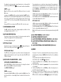
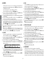
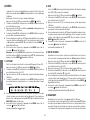
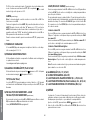
d) Connect the red wire (+) to
the positive terminal of the
battery and the black (-) wire
to the negative terminal of the
battery.
WARNING: Never replace the
original fuse by one of a dif-
ferent value.
4) BASIC OPERATIONS TO BE CARRIED OUT BEFORE USING YOUR
SET FOR THE FIRST TIME (without transmitting and without
using the “push-to-talk” switch on the microphone)
a) Connect the microphone.
b) Check the antenna connections.
c) Turn the set on by turning the volume knob VOL (1) clockwise.
d) Turn the squelch knob SQ (2) to minimum M.
e) Adjust the volume to a comfortable level.
f) Go to channel 20 by using rotary CH knob (3) or UP/DN keys (14) on the
microphone.
5) HOW TO ADJUST SWR (Standing Wave Ratio)
Warning: This must be carried out when you use your radio for the first time
and whenever you re-position your antenna. This adjustment must be car-
ried out in an obstacle-free area.
* Adjustment with internal SWR-meter
NEW, EASY AND VERY HANDY- Adjustment of SWR meter by beep tones
See menu SWR ADJUSTMENT function page 10.
* Adjustment with external SWR-meter (e.g. TOS-1 PRESIDENT)
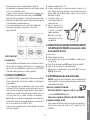
a) To connect the SWR meter :
- Connect the SWR meter between the CB radio and the antenna as close as
possible to the CB (use a maximum of 15.75” / 40 cm cable, type President
CA 2C).
b) To adjust the SWR meter:
- Set the CB on channel 20.
- Put the switch on the SWR-meter to position FWD (calibration).
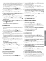
- There are two types of antenna: pre-regulated which should be used on a
good ground plane (e.g. car roof or lid of the boot), and adjustable which
offer a much larger range and can be used on a smaller ground plane (see
§ HOW TO ADJUST SWR, below).
- For an antenna which must be fixed by drilling, you will need a good contact
between the antenna and the ground plane. To obtain this, you should
lightly scratch the surface where the screw and tightening star are to be
placed.
- Be careful not to pinch or flatten the coaxial cable (as this runs the risk of
break down and/or short-circuiting).
- Connect the antenna (B).
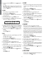
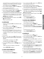
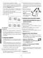
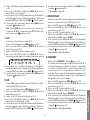
OUTPUT RADIUS PATTERN
c) Fixed antenna
- A fixed antenna should be installed in as clear space as possible. If it is fixed
to a mast, it will perhaps be necessary to stay it, according to the laws in
force (you should seek professional advice). All PRESIDENT antennas and
accessories are designed to give maximum efficiency to each CB radio
within the range.
3) POWER CONNECTION
Your PRESIDENT TAYLOR FCC 12/24 V is protected against an inversion of
polarities. However, before switching it on, you are advised to check all the
connections. Your equipment must be supplied with a continued current
of 12 or 24 volts (A). Today, most cars and lorries are negative earth. You
can check this by making sure that the negative terminal of the battery
is connected either to the engine block or to the chassis. If this is not the
case, you should consult your dealer.
a) Check that the battery is of 12 or 24 volts.
b) Locate the positive and negative terminals of the battery (+ is red and - is
black). Should it be necessary to lengthen the power cable, you should
use the same or a superior type of cable.
English

7
- Press the PTT “push-to-talk” switch (13) on the microphone to transmit.
- Bring the index needle to by using the calibration key.
- Change the switch to position REF (reading of the SWR level). The reading on
the Meter should be as near as possible to 1. If this is not the case, readjust
your antenna to obtain a reading as close as possible to 1. (A SWR reading
between 1 and 1.8 is acceptable).
- It will be necessary to recalibrate the SWR meter after each adjustment of
the antenna.
WARNING: In order to avoid any losses and attenuations in cables used for
connection between the radio and its accessories, PRESIDENT recommends
to use a cable with a length inferior to 118.11” / 3 m.
Your transceiver is now ready for use.
B) HOW TO USE YOUR TRANSCEIVER
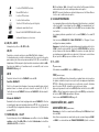
1) ON/OFF ~ VOLUME
Turn on : turn VOL knob (1) clockwise. If the function KEY BEEP is active (see
menu KEY BEEP page 10), the radio emits a beep. The radio is “on”.
Display briefly shows the microphone type setup (see menu MIC TYPE page
12).
Turn Off : turn VOL knob (1) counterclockwise until the radio emits a click
sound. Your radio is “off”.
Volume Adjustment: rotate VOL knob (1) clockwise to adjust volume. Turn
the same knob counterclockwise to reduce the sound level.
2) ASC (Automatic Squelch Control) ~ SQUELCH
Suppresses undesirable background noises when there is no communication.
Squelch does not affect neither sound nor transmission power, but allows a
considerable improvement in listening comfort.
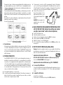
a) ASC: AUTOMATIC SQUELCH CONTROL
Worldwide patent, a PRESIDENT exclusivity.
Turn the SQ knob (2) anti-clockwise into ASC position.
appears on LCD.
No repetitive manual adjustment and a permanent improvement between
the sensitivity and the listening comfort when ASC is active. This function can
be disconnected by turning the switch clockwise. In this case the squelch
adjustment becomes manual again.
disappears from LCD.
b) MANUAL SQUELCH
Turn the SQ knob (2) clockwise to the exact point where all background
noise disappears. This adjustment should be done with precision as, if set
to maximum (fully clockwise), only the strongest signals will be received.
3) ROTARY CH KNOB
In normal operation, turn rotary CH knob (3) to adjust channel. Clockwise
to increase, counterclockwise to decrease the channel.
In MENU mode [press the F key (9) to activate this mode), see § MENU
page 9.
See § UP/DN KEYS ON THE MICROPHONE page 9.
4) S-METER
Indicates the reception level and the emitted power level.
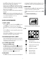
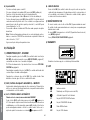
5) LCD
Indicates transmission
AM AM modulation mode (blinks in PA mode)
Automatic Squelch Control activated
BP KEY BEEP function activated
ROGER BEEP function activated
MENU mode activated
VOX VOX function activated
A Alert function activated
English

8
SCAN function activated (the dot blinks)
Indicates the selected channel
WX mode activated
Indicates frequency or menu
6) CB/PA ~ CB TB
3-position switch : CB, CB TB and PA.
CB/PA
Switch between CB and PA (Public Address) mode.
An external optional speaker can be connected to the unit to the PA.SP. jack
on the rear panel. (D). LCD indicates PA mode by blinking the modulation
mode “AM”.
For more details on operating in PA mode, see the PA SETTING menu on
page 11.
CB TB
The central position of the switch allows the activation of the TALKBACK
function.
TALKBACK function
This function allows you to hear your own modulation in the internal or
optional external speaker connected to the EXT jack. MS. (C).
When activated, LCD shows the TALKBACK level during 3 seconds.
TALKBACK level
When the function is activated, press and hold the PTT switch (13) then turn
the rotary CH knob (3) to increase (clockwise) / decrease (counterclockwise)
the volume level of the TALKBACK from 1 to 9. Release the PTT switch (13).
7) NB/ANL - HI-CUT FILTERS
3-position switch: Low position: no filter is activated. Central position: only
ANL and NB filters are enabled. High position: all filters (ANL, NB and HI-CUT)
are activated.
NB: Noise Blanker / ANL: Automatic Noise Limiter. These filters allow reducing
back ground noises and some reception interferences.
HI-CUT: Cuts out the high frequency interferences and has to be used in
accordance with the reception conditions.
8) EMERGENCY CHANNELS
Emergency channels will be automatically selected by switching this key
(8). 3-position switch: EMG1/ Emergency channel 1 is activated. EMG2 /
Emergency channel 2 is activated. OFF / No emergency channel is acti-
vated.
The default emergency channels are channel 9 (EMG1) and channel 19
(EMG2).
See the EMG SET 1 and EMG SET 2 menus page 11 to set emergency
channels.
Note: Activating an emergency channel prevents the SCAN function or
activating the PA mode. If the KEY BEEP function is activated, an error beep
sounds. “EMG” and the channel blink to indicate unauthorized handling.
Put the switch (8) to the OFF position to use these functions.
9) F ~ VOX
F
(short press)
Enter MENU. See § MENU page 9.
VOX (long press)
The VOX function allows transmitting by speaking into the original micro-
phone (or in the optional vox microphone) without pressing the PTT switch
(13). The use of an optional vox microphone connected to the rear panel
of the transceiver (E) disables the original microphone.
Long press on the VOX key (9) in order to activate the VOX function. “VOX”
appears on the display. Long press again on the VOX key (9) to disable the
function. “VOX” disappears.
See menu VOX SETTING on page 11.
10) WX MODE ~ ALERT
WX MODE
(short press)
Note: CB functions except SCAN deactivate the WX mode .
Select first a channel other than the EMG1 or EMG2. The EMERGENCY CHAN-
NEL switch (8) must be in the central OFF position. Press briefly the WX key
(10) to alternate between CB and WX modes. When WX mode is active,
“WX” is displayed. WX mode allows you to listen to weather reports. When
this mode is turned on, turn the rotary CH knob (3) or use the UP/DN (14)
keys on the microphone to search, through the 7 weather channels, for the
channel corresponding to your location (See WEATHER FREQUENCY TABLE
page 54).
English

9
The display shows the selected channel. Transmission is not allowed in this
mode. If you press PTT switch (13)
and the current weather channel blinks.
ALERT (long press)
Note: The SIREN tone only sounds in PA or CB mode. It does not sound in
WX mode.
Long press on the ALERT key (10), to activate/deactivate the ALERT function.
When the function is activated “A” is displayed. If the function is activated
and a tone is detected at the selected weather channel, then the unit
sounds “SIREN” tone. The unit cancels CB or PA mode and goes to WX
mode.
During a SIREN tone sound, press the PTT switch (13) to stop the sound.
11) USB CHARGING SOCKET
The USB socket (11) can be used to charge smartphones, tablets or other
rechargeable devices with 5 V - 2.1 A.
12) 6 PIN MICROPHONE PLUG
The plug is located on the front panel of the transceiver and makes the
setting of the equipment into the dashboard easier.
See Cabling Diagram page 55.
13) PTT (Push To Talk)
Transmission key, press to transmit a message,
is displayed. Release to
listen to an incoming communication,
disappears.
TOT (Time Out Timer)
If the PTT switch (13) is pressed for more than 3 minutes, the display starts
blinking and the transmission ends. A beep will sound until the PTT switch
(13) key is released.
14) UP/DN KEYS ON MICROPHONE ~ SCAN
UP/DN KEYS ON MICROPHONE
(short press)
Press the UP or DN button (14) on the microphone to change the channel.
UP to increase and DN to decrease the channel.
See ROTARY CH KNOB page 7.
SCAN (very long press)
Press and hold the UP or DN button (14) to activate the SCAN function. The
dot between the two channel digits flashes to indicate that the function is
active.
The scanning stops as soon as there is a busy channel. The scanning auto-
matically starts 3 seconds after the end of the transmission and if no key is
activated during 3 s. In SCANNING mode, turn the CH rotary knob (3) or
press the UP/DN keys (14) on the microphone to change scan direction.
CB channel Scan
In CB mode press and hold the UP or DN button (14) for ± 7 seconds or until
a beep sounds to activate the CB channel Scan.
Press the PTT switch (13) to exit CB Channel Scan. The dot between the two
channel digits disappears from LCD.
WX channel Scan
In WX mode press and hold the UP or DN button (14) for ± 3 seconds or until
a beep sounds to activate the WX channel Scan.
Press for 3 seconds the F key (9) to exit WX Channel Scan. The dot between
the two channel digits disappears from LCD.
Note: The WX channel scan can run in the background while using the CB
mode.
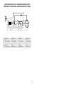
A) DC-POWER TERMINAL (13,8 V / 27,6 V)
B) ANTENNA CONNECTOR (SO-239)
C) JACK FOR EXTERNAL OPTIONAL SPEAKER (8 Ω, Ø 3.5 mm)
D) JACK FOR PA OPTIONAL SPEAKER (Public Address) (8 Ω,
Ø 3.5 mm)
E) JACK FOR OPTIONAL VOX MICROPHONE (Ø 2.5 mm)
C) MENU
The order of 11 functions is as described in this manual. However, the func-
tion displayed by entering the MENU will be the last function modified by
the user.
The procedure is the same Whatever the function is:
Press the F key (9) to enter MENU.
is displayed.
1. Turn the rotary CH knob (3) or use UP/DN keys (14) on the microphone to
select the menu.
2. Press the F key (9) to validate. The parameter of the chosen function blinks
on the display.
3. Turn the rotary CH knob (3) or use UP/DN keys (14) on the microphone to
modify the value of the parameter.
4. New press on the F key (9) to validate the chosen color. The parameter
stops blinking. a) Go to point 1 to adjust another function or b) Press the
PTT switch (13) to validate and exit MENU. disappears from the display.
English

10
5. If no key is pressed, the unit exits MENU after 10 seconds.
disappears from
the display.
Note: UP/DN keys (14) on the microphone have the same effect as the
rotation of the rotary CH knob (3). PTT switch (13) validates the last setting
and exists MENU.
disappears.
1) COLOR
This function allows to choose the backlight color of the LCD.
Press the F key (9) to enter MENU.
is displayed.
1. Turn the rotary CH knob (3) or use UP/DN keys (14) on the microphone to
select the COLOR function.
2. Press the F key (9) to validate. The current COLOR blinks on LCD.
3. Turn the rotary CH knob (3) or use UP/DN keys (14) on the microphone to
select the color. 7 available colors over and over :
4. New press on the F key (9) to validate the chosen color. The parameter
stops blinking. a) Go to point 1 to adjust another function or b) Press the
PTT switch (13) to validate and exit MENU. disappears from the display.
5. If no key is pressed, the unit exits MENU after 10 seconds, disappears from
the display.
Default COLOR is
(orange).
2) DIM
The DIM function (dimmer) allows to adjust the brightness (from1 to 9) of
the backlight or OF (no backlight).
Press the F key (9) to enter MENU.
is displayed.
1. Turn the rotary CH knob (3) or use UP/DN keys (14) on the microphone to
select the DIM function.
2. Press the F key (9) to validate. The current value blinks on LCD.
3. Turn the rotary CH knob (3) or use UP/DN keys (14) on the microphone to
select a new value.
4. New press on the F key (9) to validate. The parameter stops blinking. a)
Go to point 1 to adjust another function or b) Press the PTT switch (13) to
validate and exit MENU. disappears.
5. If no key is pressed, the unit exits MENU after 10 seconds, disappears from
the display.
Default DIMMER value is 9.
3) KEY BEEP
When the function is activated, a beep sounds when a key is pressed, by
changing the channel etc. “BP” appears on the display when the function
is active.
Press the F key (9) to enter MENU.
is displayed.
1. Turn the rotary CH knob (3) or use UP/DN keys (14) on the microphone to
select the KEyBP function.
2. Press the F key (9) to validate. The current status blinks on LCD.
3. Turn the rotary CH knob (3) or use UP/DN keys (14) on the microphone to
activate On / deactivate Of the function.
4. New press on the F key (9) to validate. The parameter stops blinking. a)
Go to point 1 to adjust another function or b) Press the PTT switch (13) to
validate and exit MENU. disappears.
5. If no key is pressed, the unit exits MENU after 10 seconds, disappears from
the display.
Default KEY BEEP is On.
4) ROGER BEEP
When the function is active, the icon
appears on the display.
The Roger Beep sounds when the PTT switch (13) on the microphone is re-
leased in order to let your correspondent speak. Historically as transceiver
is a “simplex” communication mode, it is not possible to speak and to listen
at the same time (as it is the case with a telephone). Once someone had
finished talking, he said “Roger” in order to prevent his correspondent that
it was his turn to talk. The word “Roger” has been replaced by a significant
beep. There comes “Roger beep” from.
Press the F key (9) to enter MENU.
is displayed.
1. Turn the rotary CH knob (3) or use UP/DN keys (14) on the microphone to
select the RG BP function.
2. Press the F key (9) to validate. The current status blinks on LCD.
3. Turn the rotary CH knob (3) or use UP/DN keys (14) on the microphone to
activate On / deactivate Of the function.
4. New press on the F key (9) to validate. The parameter stops blinking. a)
Go to point 1 to adjust another function or b) Press the PTT switch (13) to
validate and exit MENU. disappears.
5. If no key is pressed, the unit exits MENU after 10 seconds, disappears from
the display.
Default ROGER BEEP is Of.
5) SWR ADJUSTMENT
This function allows to adjust the SWR (Standing Wave Ratio) by beep tones.
Press the F key (9) to enter MENU.
is displayed.
English

11
1. Turn the rotary CH knob (3) or use the UP/DN keys (14) on the microphone
to select the SWR function.
2. Press the F key (9). The radio automatically goes to TX mode without press-
ing PTT switch (13) . The SWR measurement starts. Measurement time is 5
minutes maximum. The remaining time is displayed.
3. Adjust your antenna.
4. The beep tone* is continuous when SWR value is equal to1.0. The space
between two beeps becomes longer when SWR value moves away from1.0.
Volume of the beep tone is adjustable with VOLUME knob (1).
Display shows the SWR value. For example 2.5.
5. Press the PTT switch (13) to exit MENU mode.
disappears from the display.
*Please check that the beep volume is set to a comfortable listening level.
See § HOW TO ADJUST SWR page 6.
6) EMG SET 1
Allows to set the channel for Emergency Channel 1.
Press the F key (9) to enter MENU.
is displayed.
1. Turn the rotary CH knob (3) or use UP/DN keys (14) on the microphone to
select the EMG 1 function.
2. Press the F key (9) to validate. The current channel blinks on LCD.
3. Turn the rotary CH knob (3) or use UP/DN keys (14) on the microphone to
select the emergency channel.
4. New press on the F key (9) to validate. The channel stops blinking. a) Go to
point 1 to adjust another function or b) Press the PTT switch (13) to validate
and exit MENU. disappears.
5. If no key is pressed, the unit exits MENU after 10 seconds, disappears from
the display.
Default emergency channel 1 is 9.
See § EMERGENCY CHANNELS page 8.
7) EMG SET 2
Allows to set the channel for Emergency Channel 2.
Press the F key (9) to enter MENU.
is displayed.
1. Turn the rotary CH knob (3) or use UP/DN keys (14) on the microphone to
select the EMG 2 function.
Points 2 to 5 are identical to § EMG SET 1.
Default Emergency channel 2 is 19.
See § EMERGENCY CHANNELS page 8.
8) VOX SETTING
Press the F key (9) to enter MENU. is displayed.
1. Turn the rotary CH knob (3) or use UP/DN keys (14) on the microphone to
select the VOX function.
Three adjustments are possible: Sensitivity L / Anti-vox level A / Vox delay time
t (over and over).
2. Press the F key (9). The current setting (L, A or t) blinks on the LCD.
3. Turn the rotary CH knob (3) or press the UP/DN (14) keys on the microphone
to move to next setting or...
4. Press the F key (9). The value of the current setting blinks on the LCD.
5. Turn the rotary CH knob (3) or press the UP/DN (14) keys on the microphone
to adjust the value of the setting.
6. Press the F key (9) to store and validate the setting.
7. Go to point 2 to set both others adjustments of VOX.
8. Once the settings done, press the PTT switch (13) to exit the VOX Adjustment
mode. If no adjustment is made for 10 seconds, the unit automatically exits
the function.
- Sensitivity L: allows the adjustment of the microphone (original one or
optional vox) for an optimum transmission quality. Adjustable level from1
(high level) to 9 (low level).Default value: 5.
- Anti-Vox A: allows disabling the transmission generated by the surrounding
noise. The level is adjustable. OF (according the squelch level) and from 0
(without anti-vox) to 9 (low level). Default value: OF.
- Delay time t: allows avoiding the sudden cut of the transmission by adding
a delay at the end of speaking. The level is adjustable from 1 (short delay)
to 9 (long delay). Default value; 1.
VOX SETTING don’t automatically activate the VOX function.
9) PA SETTING
This function allows to select the operating mode of Public Address.
Press the F key (9) to enter MENU.
is displayed.
1. Turn the rotary CH knob (3) or use UP/DN keys (14) on the microphone to
select the PASET function.
2. Press the F key (9) to validate. The current value blinks on LCD.
3. Turn the rotary CH knob (3) or use UP/DN keys (14) on the microphone to
select the operating mode of the PA : In , OF or PA.
4. New press on the F key (9) to validate. The parameter stops blinking. a)
Go to point 1 to adjust another function or b) Press the PTT switch (13) to
validate and exit MENU. disappears.
5. If no key is pressed, the unit exits MENU after 10 seconds, disappears from
the display.
In : the modulation of the microphone is transmitted to external loudspeaker
connected to jack PA.SP. (D). The received signal is transmitted to the
English

12
internal loudspeaker [or external optional loudspeaker connected to jack
EXT.SP (C)]. “AM” blinks on the LCD.
OF: The reception is no more functional. Only the modulation of the micro-
phone is transmitted to the Public Address loudspeaker connected to jack
PA.SP. (D). PA and PA volume level are displayed.
PA: the modulation of the microphone and the received signal are transmit-
ted to the Public Address loudspeaker connected to jack PA.SP. (D). The
used modulation mode “AM” blinks on the LCD.
The VOL knob (1) allows adjust PA volume.
Default PA setting is: In .
See § CB/PA (Public Address) page 8.
10) MIC TYPE
The PRESIDENT TAYLOR FCC 12/24 V can be used with an electret micro-
phone as well as with the dynamic one, 6-pin PRESIDENT (see the cabling
diagram page 55). Turning on the unit, the type of the microphone is
briefly displayed.
Press the F key (9) to enter MENU.
is displayed.
1. Turn the rotary CH knob (3) or use UP/DN keys (14) on the microphone to
select the MICTP function.
2. Press the F key (9) to validate. The current parameter blinks on LCD.
3. Turn the rotary CH knob (3) or use UP/DN keys (14) on the microphone to
select the type on the microphone EL (electret) or DY (dynamic).
4. New press on the F key (9) to validate. The parameter stops blinking. a)
Go to point 1 to adjust another function or b) Press the PTT switch (13) to
validate and exit MENU. disappears.
5. If no key is pressed, the unit exits MENU after 10 seconds, disappears from
the display.
Default type of microphone is EL (electret).
11) RESET
Restores all factory settings.
Press the F key (9) to enter MENU.
is displayed.
1. Turn the rotary CH knob (3) or use UP/DN keys (14) on the microphone to
select the RESET function.
2. Press the F key (9) to validate. AL blinks on LCD.
3. New press on the F key (9) to reset. The unit exits MENU. disappears.
4. If no key is pressed, the unit exits MENU after 10 seconds. disappears
D) TECHNICAL CHARACTERISTICS
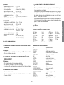
1) GENERAL
- Channels : 40
- Modulation modes : AM
- Frequency range : from 26.965 MHz to 27.405 MHz
- Weather channels : from162.400 MHz to 162.550 MHz
- Antenna impedance : 50 ohms
- Power supply : 13.8 V / 27.6 V
- Dimensions : 5.905 (W) x 6.496 (D) x 1.771 (H) inches
150 (W) x 165 (D) x 45 (H) mm
- Weight : ± 1.653 lbs / 0.750 kg
- Accessories supplied : 1 microphone electret UP/DOWN with
support, mounting cradle, screws and
fused power cord.
2) TRANSMISSION
- Frequency allowance : +/- 200 Hz
- Carrier power : 4 W
- Transmission interference : inferior to 4 nW (- 54 dBm)
- Audio response : 300 Hz to 3 KHz
- Emitted power in the adj. channel : inferior to 20 µW
- Microphone sensitivity : 3.0 mV
- Drain : < 2 A @ 13.8 V / <1.5 A @ 27.6 V
- Modulated signal distortion : 2 %
3) RECEPTION
- Maxi. sensitivity at 20 dB sinad : 0.5 µV - 113 dBm
- Frequency response : 300 Hz to 3 kHz
- Adjacent channel selectivity : 60 dB
- Maximum audio power : 3 W
- Squelch sensitivity : minimum 0.2 µV - 120 dBm
: maximum 1 mV - 47 dBm
- Frequency image rejection rate : 60 dB
- Intermediate frequency rej. rate : 70 dB
- Drain : 150 ~ 500 mA (13.8 V)
100 ~ 300 mA (27.6 V)
English

13
E) TROUBLE SHOOTING
1) YOUR RADIO WILL NOT TRANSMIT OR YOUR TRANSMISSION
IS OF POOR QUALITY
- Check that the antenna is correctly connected and that the SWR is properly
adjusted.
- Check that the microphone is properly plugged in.
2) YOUR RADIO WILL NOT RECEIVE OR RECEPTION IS POOR
- Check that the squelch level is properly adjusted.
- Check that the volume (1) is set to a comfortable listening level.
- Check that the antenna is correctly connected and that the SWR is properly
adjusted.
3) YOUR RADIO WILL NOT LIGHT UP
- Check the power supply.
- Check the connection wiring.
- Check the fuse.
F) HOW TO TRANSMIT OR RECEIVE A MESSAGE ?
Now that you have read the manual, make sure that your CB Radio is ready
for use (i.e. check that your antenna is connected).
Press the «push-to-talk» switch (13) and announce your message «Attention
stations, transmission testing» which will allow you to check the clearness
and the power of your signal. Release the switch and wait for a reply. You
should receive a reply like, «Strong and clear».
If you use a calling channel (19) and you have established communication
with someone, it is common practice to choose another available channel
so as not to block the calling channel.
G) GLOSSARY
INTERNATIONAL PHONETIC ALPHABET
A Alpha H Hotel O Oscar V Victor
B Bravo I India P Papa W Whiskey
C Charlie J Juliett Q Quebec X X-ray
D Delta K Kilo R Romeo Y Yankee
E Echo L Lima S Sierra Z Zulu
F Foxtrott M Mike T Tango
G Golf N November U Uniform
TECHNICAL VOCABULARY
AM : Amplitude Modulation
CB : Citizen’s Band
CH : Channel
CW : Continuous Wave
DX : Long Distance Liaison
DW : Dual Watch
FM : Frequency Modulation
GMT : Greenwich Meantime
HF : High Frequency
LF : Low Frequency
LSB : Lower Side Band
RX : Receiver
SSB : Single Side Band
SWR : Standing Wave Ratio
SWL : Short Wave Listening
SW : Short Wave
TX : CB Transceiver
UHF : Ultra High Frequency
USB : Upper Side Band
VHF : Very High Frequency
CB LANGUAGE
Advertising : Flashing lights of police car
Back off : Slow down
Basement : Channel 1
Base station : A CB set in fixed location
Bear : Policeman
Bear bite : Speeding fine
Bear cage : Police station
Big slab : Motorway
Big 10-4 : Absolutely
Bleeding : Signal from an adjacent channel interfering
with the transmission
Blocking the channel : Pressing the PTT switch without talking
Blue boys : Police
Break : Used to ask permission to join
a conversation
Breaker : A CBer wishing to join a channel
Clean and green : Clear of police
Cleaner channel : Channel with less interference
English

14
Coming in loud and proud : Good reception
Doughnut : Tyre
Down and gone : Turning CB off
Down one : Go to a lower channel
Do you copy? : Understand?
DX : Long distance
Eighty eights : Love and kisses
Eye ball : CBers meeting together
Good buddy : Fellow CBer
Hammer : Accelerator
Handle : CBer’s nickname
Harvey wall banger : Dangerous driver
How am I hitting you? : How are you receiving me?
Keying the mike : Pressing the PTT switch without
talking
Kojac with a kodak : Police radar
Land line : Telephone
Lunch box : CB set
Man with a gun : Police radar
Mayday : SOS
Meat wagon : Ambulance
Midnight shopper : Thief
Modulation : Conversation
Negative copy : No reply
Over your shoulder : Right behind you
Part your hair : Behave yourself - police ahead
Pull your hammer back : Slow down
Rat race : Congested traffic
Rubberbander : New CBer
Sail boat fuel : Wind
Smokey dozing : Parked police car
Smokey with a camera : Police radar
Spaghetti bowl : Interchange
Stinger : Antenna
Turkey : Dumb CBer
Up one : Go up one channel
Wall to wall : All over/everywhere
What am I putting to you? : Please give me an S-meter
reading
English

15
#
GENERAL WARRANTY CONDITIONS
English
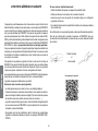
If you note a malfunction:
• Check the power supply of your device and the quality of the fuse.
• Check that the antenna, the microphone are correctly connected.
• Check that the squelch level is properly adjusted; the programmed configuration is the
correct one.
• In the event of a real malfunction, please contact your dealer first. He will decide what
action should be taken.
In case of an intervention not covered by warranty, an estimate will be established before
any repair.
Thank you for your confidence in the PRESIDENT quality and experience. We recommend
that you read this manual carefully so that you are completely satisfied with your purchase.
Technical Manager
and
Quality Manager
This device is guaranteed 2 years parts and labour in its country of purchase against
any manufacturing defects validated by our technical department. PRESIDENT After Sales
Service department reserves the right not to apply the warranty in the event a breakdown
is caused by an antenna other than those distributed by PRESIDENT. An extension of 3
years warranty is proposed systematically for the simultaneous purchase of a device and
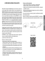
a PRESIDENT antenna, bringing the total duration of the warranty to 5 years. In order to
be valid, the warranty registration must be completed and submitted within a period of 30
days after the purchase date to PRESIDENT ELECTRONICS online at
www.president-
electronics.us/warranty-registration
. You can also access this warranty registration
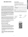
page by using your smartphone to read (application must be available) the QR code. You
will receive a confirmation email if the registration is successfully completed. Please keep a
copy of this email for your records.
Any repair under warranty will be without charge and the return delivery costs will be borne
by PRESIDENT. A proof of purchase sales receipt must be included with the device to be
repaired. The dates listed on the warranty registration and proof of purchase must match.
In case the device is not under warranty, the repair and return of the device will be charged.
No spare parts will be sent nor exchanged by PRESIDENT under warranty. Do not proceed
with the installation of the device without reading the user manual.
The warranty is only valid in the country of purchase.
Exclusions (not covered by Warranty):
• Damages caused by accident, shock or inadequate packaging.
• Power transistors, microphones, lights, fuses and the disrespect of the installation and use
of specifications (including but not limited to antenna used with too high power, final output
power transistors (SWR), inversion of polarities, bad connections, over voltage…).
• The warranty cannot be extended due to the non-availability of the device while it is being
serviced at PRESIDENT After Sales Service department, nor by a change of one or more
components or spare parts.
• Transceivers which have been modified. The warranty application is excluded in case
of modification or poor maintenance done by a third party not approved by PRESIDENT
ELECTRONICS.
Warranty Registration

16
Español
La garantía de este artículo sólo es válida en el país de compra.
¡ ATENCIÓN !
Antes de la utilización tengan cuidado de
nunca emitir sin haber previamente conec-
tado la antena (conector “B” situado en la
parte trasera de su equipo), ajustada la ROE
(Relación de Ondas Estacionarias)! Sino, se
expone a dañar el amplificador de potencia,
no cubierto por la garantía.
WARNING: This product can expose you to chemicals including Lead, which is known to the State of California to cause cancer and birth defects or other repro-
ductive harm. For more information go to www.P65Warnings.ca.gov.
AVERTISSEMENT : Ce produit peut vous exposer à des agents chimiques, y compris le plomb, identifiés par l’État de Californie comme pouvant causer le cancer et
des malformations congénitales ou autres effets nocifs sur la reproduction. Pour de plus amples informations, prière de consulter le site www.P65Warnings.ca.gov.

17
Bienvenido al mundo de los emisores-receptores CB de última generación. Esta
nueva gama de estaciones le permite acceder a la comunicación electrónica
más competitiva. Gracias a la utilización de tecnología punta que garantiza
una calidad sin precedentes, su PRESIDENT TAYLOR FCC 12/24 V representa un
nuevo hito en la facilidad de uso y la solución por excelencia para el usuario
más exigente de CB. Para sacar el máximo partido de todas sus posibilidades,
le aconsejamos leer atentamente estas instrucciones de uso antes de instalar
y utilizar su CB PRESIDENT TAYLOR FCC 12/24 V.
A) INSTALACIÓN
1) ELEGIR EL EMPLAZAMIENTO Y MONTAJE DEL PUESTO MÓVIL
a) Escoja el emplazamiento más apropiado para una utilización simple y
práctica de su estación móvil.
b) Procure que no moleste ni al conductor ni a los pasajeros del vehículo.
c) Prevea el paso y la protección de los diferentes cables, (alimentación,
antena, accesorios) con el fin de que en ningún caso perturben la con-
ducción del vehículo.
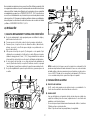
d) Utilice para el montaje el soporte (1) entregado con el aparato, fíjelo
sólidamente con ayuda de los tornillos auto-roscantes (2) proporcionados
(diámetro de agujero de 3,2 mm / 1,126”). Tenga cuidado de no dañar el
sistema eléctrico del vehículo en el momento del taladro del salpicadero.
e) En el momento del montaje, no se olvide de insertar las arandelas de
caucho (3) entre la estación y su soporte. Éstas tienen, en efecto, un papel
“amortiguador” y permiten una orientación y presión suaves de la estación.
f) Escoja un emplazamiento para el soporte del micro y prevea el paso de
su cable.
- NOTA: Su estación móvil que posee una toma de micro en la parte frontal
puede ser empotrada en el cuadro de mandos. En ese caso, se recomienda
añadirle un altavoz externo para una mejor escucha de las comunicaciones
(conector EXT.SP situado en la cara posterior del aparato: C). Infórmese
con su vendedor más próximo para el montaje en su aparato.
2) INSTALACIÓN DE LA ANTENA
a) Elección de la antena
- En CB, cuanto más grande es una antena, mejor es su rendimiento. Su
Centro de Asesoramiento sabrá orientarle en su elección.
b) Antena móvil
- Hay que instalarla en un lugar del vehículo donde haya un máximo de
superficie metálica (plano de masa), alejándose de los montantes del
parabrisas y de la luneta trasera.
- En caso de que se haya instalado una antena de radio-teléfono, la antena
CB debe estar por encima de ésta.
- Existen 2 tipos de antenas: las preajustadas y las regulables.
Español

18
- Las preajustadas se utilizan preferentemente con un buen plano de masa
(en el techo o en el maletero).
- Las regulables ofrecen un campo de uso mucho más ancho y permiten
sacar partido de planos de masa menos importantes (véase § AJUSTE DE
LA ROE por debajo).
- Para una antena de fijación por taladro, es necesario tener un contacto
excelente entre la antena y el plano de masa; para ello, rasque ligeramente
la chapa al nivel del tornillo y de la estrella de presión.
- En el momento del paso del cable coaxial, tenga cuidado de no pelliz-
carlo ni aplastarlo (riesgo de rotura o cortocircuito).
- Conecte la antena (B).
c) Es necesario conectar sobre un (+) y (-) permanentes. Les aconsejamos
enchufar directamente el cable de alimentación en la batería (el enchufe
sobre el cable del auto-radio o sobre otras partes del circuito electrónico
podrán en ciertos casos fa-
vorecer la recepción de las
señales parásitas).
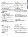
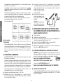
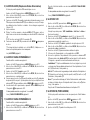
d) Conecten el hilo rojo (+) al borne
positivo de la batería y el hilo
negro (-) al borne negativo de
la batería.
ATENCIÓN: ¡No reemplace ja-
más el fusible de origen por un
modelo de un valor diferente!
4) OPERACIONES DE BASE QUE HAY QUE EFECTUAR ANTES
DE LA PRIMERA UTILIZACIÓN, SIN PASAR POR EMISIÓN (sin
apretar la palanca del micro)
a) Conecte el micro,
b) Verifique la conexión de la antena,
c) Puesta en marcha del aparato: gire el botón del volumen VOL (1) en el
sentido de las agujas del reloj hasta oír un “clic”,
d) Gire el botón del squelch SQ (2) al mínimo, en la posición M,
e) Ajuste el volumen (1) a un nivel conveniente,
f) Dirija la estación al canal 20 con ayuda del conmutador rotativo CH (3) o
de los botones UP/DN (14) del micrófono.
5) AJUSTE DE LA ROE (Relación de Ondas Estacionarias)
ATENCIÓN: Esta operación debe efectuarse necesariamente en el momento
de la primera utilización del aparato o en el momento de un cambio de
antena. Este ajuste debe se realizar en un lugar abierto, al aire libre.
* Ajuste con el medidor de ROE integrado
NUEVO, FÁCIL Y MUY ÚTIL - ajuste mediante “pitidos”
Véase el menú AJUSTE DE LA ROE página 23.
* Ajustes con el medidor de ROE externo (tipo TOS-1 PRESIDENT):
a) Empalme del medidor de ROE
- Conecte el medidor de ROE entre la estación y la antena, lo más cerca
posible de la estación (utilice para ello un cable de 40 cm / 15,75” máximo
tipo CA-2C PRESIDENT).
Lóbulo de radiación
c) Antena fija
- Procure abrirla al máximo. En caso de fijación sobre un poste, habrá que
sostenerla eventualmente conforme a las normas vigentes (infórmese con
un profesional). Las antenas y los accesorios PRESIDENT han sido especial-
mente concebidos para un rendimiento óptimo de todos los aparatos de
la gama.
3) CONEXIÓN DEL ALIMENTADOR
Su PRESIDENT TAYLOR FCC 12/24 V está provista de una protección contra
las inversiones de polaridad.
Vuestra emisora debe estar alimentada por una fuente de corriente continua
de 12 o 24 voltios (A). En este momento, la mayor parte de los coches y
camiones funcionan con una toma de tierra negativa, se puede asegurar
verificando que el terminal (-) de la batería esté bien conectado al bloque
del motor o bastidor. En el caso contrario, consulte con su suministrador.
Todas las operaciones de conexión siguientes, deben efectuarse con el
cable de alimentación no conectado a la emisora:
a) Asegúrense que el alimentador sea de 12 o 24 Voltios.
b) Identifique los polos (+) y (-) de la batería (+ = rojo, - = negro). En el caso
que sea necesario alargar el cable de alimentación utilice un cable de
sección equivalente o superior.
Español

19
b) Ajuste de la ROE
- Posicione la estación hacia el canal 20.
- Sitúe el conmutador del medidor de ROE en posición FWD (calibración).
- Apriete la palanca PTT (13) del micro para pasar a emisión.
- Dirija la aguja al índice ▼ con ayuda del botón de calibración.
- Ponga el conmutador en posición REF (lectura del valor de la ROE). El valor leído
en el indicador debe estar muy cerca de 1. En caso contrario, reajuste su antena
hasta obtener un valor lo más cerca posible a 1 (puede aceptarse un valor de la
ROE comprendido entre 1 y 1,8).
- Es necesario recalibrar el medidor de ROE entre cada operación de ajuste
de la antena.
Observación: Con el fin de evitar las pérdidas y las atenuaciones en los
cables de conexión entre la radio y sus accesorios, PRESIDENT recomienda
una longitud de cable inferior a 3 m / 118,11”.
Ahora, su estación está preparada para funcionar.
B) UTILIZACIÓN
1) ENCENDIDO-APAGADO / VOLUMEN
Para encender la emisora: gire el botón VOL (1) hacia la derecha. Si la
función PITIDO DE TECLADO está activa (véase página 22), sonará un
pitido. Su radio está encendida “on”.
La pantalla muestra brevemente el tipo de micrófono (véase el menú TIPO
DE MICRÓFONO página 24).
Para apagar el equipo: gire el botón VOL (1) hacia la izquierda hasta que
escuche un clic. Su radio está apagada “off”.
Para ajustar el volumen, gire el mando VOL (1) hacia la derecha. Para
disminuir el volumen, gire el mando en sentido antihorario.
2) ASC (Automatic Squelch Control) / SQUELCH
Esta función permite suprimir los ruidos de fondo indeseables en ausencia
de comunicación.
El squelch no actúa ni sobre el volumen sonoro ni sobre la potencia de
emisión, pero permite mejorar considerablemente la comodidad de es-
cucha.
a) ASC : SQUELCH CON AJUSTE AUTOMÁTICO
Patente mundial, exclusiva de PRESIDENT
Gire el botón del squelch SQ (2) en el sentido contrario a las agujas del
reloj en la posición ASC.
aparece en el display. Evita el ajuste manual
repetitivo y permite la optimización permanente entre la sensibilidad y la
comodidad de escucha. Esta función puede desactivarse por rotación
del botón en el sentido de las agujas del reloj. En ese caso, el ajuste del
squelch vuelve a ser manual.
desaparece del display.
b) SQUELCH MANUAL
Gire el botón del squelch SQ (2) en el sentido de las agujas del reloj hasta
el punto exacto en que desaparezca cualquier ruido de fondo. Este ajuste
debe efectuarse con precisión, porque, en posición máxima en el sentido
de las agujas del reloj, sólo las señales más fuertes pueden ser percibidas.
3) CONMUTADOR ROTATIVO CH
En el modo normal, gire el conmutador rotativo CH (3) para cambiar el
canal. Gire en el sentido de las agujas del reloj para aumentar y en sentido
antihorario para disminuir de un canal.
En el modo MENÚ [apriete la tecla F (9) para activar este modo), véase
§ MENÚ página 22.
Véase § BOTONES UP/DN DEL MICRÓFONO página 21.
4) VÚMETRO
Muestra el nivel de recepción y la salida del nivel de potencia.
5) PANTALLA LCD
Indica la emisión
AM Modo de modulación AM (parpadea en el modo PA)
Automatic Squelch Control activado
BP Función PITIDO DE TECLADO activado
Función ROGER BEEP activada
Modo MENÚS activado
Español

20
VOX Función VOX activada
A Función Alerta activada
Función SCAN activada (el punto parpadea)
Indica el canal seleccionado
Modo CANALES METEOROLÓGICOS activado
Indica la frecuencia y el menú
6) CB/PA ~ CB TB
Conmutador de 3 posiciones: CB, CB TB y PA.
CB/PA
Permite cambiar entre los modos CB y PA (Public Address, megafonía).
Se puede conectar un altavoz de sonido exterior al equipo a través de una
toma en el panel trasero PA.SP. (D). El modo PA se indica en la pantalla
mediante el modo de modulación “AM” parpadeante.
Para mas detalles sobre el funcionamiento del PA, véase el menú AJUSTE
DEL PA página 24.
CB TB
La posición central del conmurtador activa la función TALKBACK en modo
CB.
Función TALKBACK
Esta función le permite escuchar su propia modulación en el altavoz interno
o externo opcional, conectado a la toma EXT. MS. (C).
Cuando se activa el modo TALKBACK, el nivel del TALKBACK aparece
durante 3 segundos.
Nivel del TALKBACK
Cuando la función está activa, mantenga pulsada la palanca de emisión
PTT (13) y gire el conmutador rotativo CH (3) para aumentar/disminuir el
nivel de volumen del TALKBACK de1 a 9. Suelte la palanca de emisión PTT
(13).
7) FILTROS NB/ANL - HI-CUT
Conmutador de 3 posiciones: posición baja: no hay filtro activado. Posición
central: solo los filtros ANL y NB están activados. Posición alta: todos los filtros
(ANL, NB y HI-CUT) están activados.
NB: Noise Blanker / ANL: limitador de ruido automático. Estos filtros reducen
el ruido de fondo y algunos parásitos de recepción.
HI-CUT: elimina las interferencias de alta frecuencia y se debe utilizar de
acuerdo con las condiciones de recepción.
8) CANALES DE EMERGENCIA
Los canales de emergencia se seleccionarán automáticamente al cambiar
este conmutador (8). 3 posiciones: EMG1 / El canal de emergencia 1 está
activado. EMG2 / El canal de emergencia 2 está activado. OFF / no se
activa ningún canal de emergencia.
Los canales de prioridad predeterminados son 9/AM (EMG1) y 19/AM (EMG2)
Consulte el menú AJUSTE DEL CANAL DE EMERGENCIA 1 y 2 en la página
23 para configurar los canales de emergencia.
Nota: La activación de un canal prioritario no permite la utilización de
la función SCAN o habilitar el modo PA. Si la función PITIDO DE TECLADO
está activada, un pitido de error se emite. “EMG” y el canal parpadean
el la pantalla para indicar una manipulación no autorizada. Posicione el
conmutador (8) en la posición OFF para usar estas funciones.
9) F ~ VOX
F
(presión breve)
Entra en los MENÚS (véase el § MENÚS página 22).
VOX (presión larga)
La función VOX permite emitir hablando en el micro de origen (o en el
micro vox opcional) sin apretar la palanca PTT (13). La utilización de un
micro vox opcional conectado detrás del aparato (E) desactiva el micro
de origen.
Apriete largamente el botón VOX (9) para activar la función VOX. Aparece
en el visualizador el icono “VOX”. Una nueva presión larga en el botón VOX
(9)desactiva la función. El icono “VOX” desaparece de la pantalla.
Véase el menú AJUSTE DEL VOX página 23.
10) CANALES METEOROLÓGICO (WX) ~ ALERTA
CANALES METEOROLÓGICOS (WX)
(presión breve)
Nota : Las funciones de la CB excepto el SCAN desactivan el modo WX.
Seleccione primero un canal distinto de los canales de emergencia EMG1
o EMG2. El conmutador CANALES DE EMERGENCIA (8) debe estar en la
posición OFF. Pulse brevemente la tecla WX (10) para cambiar entre los
modos CB y WX. Cuando el modo meteorológico (WX) está activo, apa-
rece “WX” en la pantalla. El modo WX le permite escuchar los informes
meteorológicos. Cuando se activa este modo, gire el conmutador rotativo
Español
A página está carregando ...
A página está carregando ...
A página está carregando ...
A página está carregando ...
A página está carregando ...
A página está carregando ...
A página está carregando ...
A página está carregando ...
A página está carregando ...
A página está carregando ...
A página está carregando ...
A página está carregando ...
A página está carregando ...
A página está carregando ...
A página está carregando ...
A página está carregando ...
A página está carregando ...
A página está carregando ...
A página está carregando ...
A página está carregando ...
A página está carregando ...
A página está carregando ...
A página está carregando ...
A página está carregando ...
A página está carregando ...
A página está carregando ...
A página está carregando ...
A página está carregando ...
A página está carregando ...
A página está carregando ...
A página está carregando ...
A página está carregando ...
A página está carregando ...
A página está carregando ...
A página está carregando ...
A página está carregando ...
A página está carregando ...
A página está carregando ...
A página está carregando ...
A página está carregando ...
-
 1
1
-
 2
2
-
 3
3
-
 4
4
-
 5
5
-
 6
6
-
 7
7
-
 8
8
-
 9
9
-
 10
10
-
 11
11
-
 12
12
-
 13
13
-
 14
14
-
 15
15
-
 16
16
-
 17
17
-
 18
18
-
 19
19
-
 20
20
-
 21
21
-
 22
22
-
 23
23
-
 24
24
-
 25
25
-
 26
26
-
 27
27
-
 28
28
-
 29
29
-
 30
30
-
 31
31
-
 32
32
-
 33
33
-
 34
34
-
 35
35
-
 36
36
-
 37
37
-
 38
38
-
 39
39
-
 40
40
-
 41
41
-
 42
42
-
 43
43
-
 44
44
-
 45
45
-
 46
46
-
 47
47
-
 48
48
-
 49
49
-
 50
50
-
 51
51
-
 52
52
-
 53
53
-
 54
54
-
 55
55
-
 56
56
-
 57
57
-
 58
58
-
 59
59
-
 60
60


PRESIDENT Taylor FCC Manual do proprietário
- Tipo
- Manual do proprietário
em outros idiomas
Artigos relacionados
-
PRESIDENT Richard Manual do proprietário
-
PRESIDENT TXUS610 Manual do proprietário
-
PRESIDENT WALKER II FCC Manual do proprietário
-
PRESIDENT MC-KINLEY-USA Manual do proprietário
-
-
-
PRESIDENT Ronald 12M Manual do proprietário
-
-
-
PRESIDENT JOHNSON II Manual do proprietário