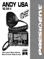
PRESIDENT Andy USA Manual do proprietário
- Tipo
- Manual do proprietário

12/24 V
Owner’s manual / Manuel d’utilisation
Manual del usuario / Manual do usuário
with / avec / con / com
Downloaded from www.cbradio.nl

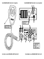
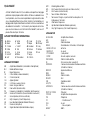
Un vistazo a vuestro PRESIDENT ANDY USA12/24 V
Your PRESIDENT ANDY USA12/24 V at a glance Votre PRESIDENT ANDY USA12/24 V en un coup d'œil
Uma olhada no seu PRESIDENT ANDY USA 12/24 V

3
SOMMAIRE
INSTALLATION 15
UTILISATION 17
FONCTIONS À L’ALLUMAGE DE L’APPAREIL 19
FONCTIONS AVEC LA PÉDALE D’ÉMISSION PTT 20
CARACTÉRISTIQUES TECHNIQUES 21
GUIDE DE DÉPANNAGE 21
COMMENT ÉMETTRE/RECEVOIR UN MESSAGE 21
GLOSSAIRE 22
CONDITIONS GÉNÉRALES DE GARANTIE 24
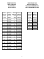
TABLEAUX DES FRÉQUENCES 47
Français
SUMARIO
INSTALACIÓN 26
UTILIZACIÓN 28
FUNCIONES AL ENCENDER LA EMISORA 30
FUNCIONES CON LA PALANCA DE EMISIÓN PTT 31
CARACTERÍSTICAS TÉCNICAS 32
GUÍA DE PROBLEMAS 32
COMO EMITIR O RECIBIR UN MENSAJE 32
LÉXICO 33
CONDICIONES GENERALES DE GARANTÍA 35
TABLAS DE FRECUENCIAS 47
Español
English
Português
SUMMARY
INSTALLATION 5
HOW TO USE YOUR CB 7
FUNCTIONS TURNING ON THE UNIT 9
FUNCTIONS WITH PTT SWITCH 10
TECHNICAL CHARACTERISTICS 10
TROUBLE SHOOTING 11
HOW TO TRANSMIT OR RECEIVE A MESSAGE 11
GLOSSARY 11
GENERAL WARRANTY CONDITIONS 13
FREQUENCY TABLES 47
SUMÁRIO
INSTALAÇÃO 37
UTILIZAÇÃO 39
FUNÇÕES AO LIGAR O APARELHO 41
FUNÇÕES COM A ALAVANCA DE EMISSÃO PTT 42
CARACTERÍSTICAS TÉCNICAS 43
GUIA DE PROBLEMAS 43
COMO TRANSMITIR OU RECEBER UMA MENSAGEM 43
GLOSSÁRIO 44
CONDIÇÕES GERAIS DE GARANTIA 46
TABELAS DE FREQUÊNCIAS 47

4
The guarantee of this transceiver is valid only in the country of purchase.
English
PROPOSITION 65 WARNING: This product contains a chemical known to the State of California to cause cancer and birth defects or other reproductive harm.
WARNING !
Before using, be careful never to transmit without first
having connected the antenna (connection “B” situated
on the back panel of the equipment) or without having
set the SWR (Standing Wave Ratio) ! Failure to do so may
result in destruction of the power amplifier, which is not
covered by the warranty.

5
Welcome to the world of the new generation of CB radios. The
new PRESIDENT range gives you access to top performance
CB equipment. With the use of up-to-date technology, which
guarantees unprecedented quality, your PRESIDENT ANDY USA
12/24 V is a new step in personal communication and is the
surest choice for the most demanding of professional CB radio
users. To ensure that you make the most of all its capacities,
we advise you to read carefully this manual before installing
and using your PRESIDENT ANDY USA 12/24 V.
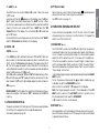
A) INSTALLATION
1) WHERE AND HOW TO MOUNT YOUR MOBILE CB RADIO
a) You should choose the most appropriate setting from a simple and
practical point of view.
b) Your CB radio should not interfere with the driver or the passengers.
c) Remember to provide for the passing and protection of different
wires (e.g. power, antenna, accessory cabling) so that they do not
in any way interfere with the driving of the vehicle.
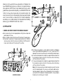
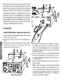
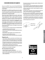
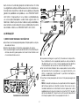
d) To install your equipment, use the cradle (1) and the self-tapping
screws [2] provided (drilling diameter 3.2 mm). Take care not to
damage the vehicle’s electrical system while drilling the dash board.
e) Choose where to place the microphone support and remember that
the microphone cord must stretch to the driver without interfering
with the controls of the vehicle.
f) Choose where to place the microphone support and remember that
the microphone cord must stretch to the driver without interfering
with the controls of the vehicle.
- Note: As the transceiver has a frontal microphone socket, it can be
set into the dash board. In this case, you will need to add an exter-
nal loud speaker to improve the sound quality of communications
(connector EXT.SP situated on the back panel: C). Ask your dealer
for advice on mounting your CB radio.
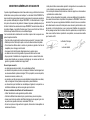
MOUNTING DIAGRAM
EnglishEnglish

6
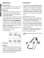
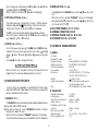
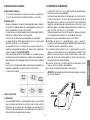
2) ANTENNA INSTALLATION
a) Choosing your antenna
- For CB radios, the longer the antenna, the better its results. Your
dealer will be able to help you with your choice of antenna.
b) Mobile antenna
- Must be fixed to the vehicle where there is a maximum of metallic
surface (ground plane), away from windscreen mountings.
- If you already have a radio-telephone antenna installed, the CB
antenna should be higher than this.
- There are two types of antenna: pre-regulated which should be
used on a good ground plane (e.g. car roof or lid of the boot), and
adjustable which offer a much larger range and can be used on
a smaller ground plane (see § 5 page 7, ADJUSTMENT OF SWR).
- For an antenna which must be fixed by drilling, you will need a
good contact between the antenna and the ground plane. To
obtain this, you should lightly scratch the surface where the screw
and tightening star are to be placed.
- Be careful not to pinch or flatten the coaxial cable (as this runs the
risk of break down and/or short-circuiting).
- Connect the antenna (B).
3) POWER CONNECTION
Your PRESIDENT ANDY USA 12/24 V is protected against an inversion
of polarities. However, before switching it on, you are advised to
check all the connections. Your equipment must be supplied with a
continued current of 12 or 24 volts (A). Today, most cars and lorries
are negative earth. You can check this by making sure that the
negative terminal of the battery is connected either to the engine
block or to the chassis. If this is not the case, you should consult your
dealer.
a) Check that the battery is of 12 or 24 volts.
b) Locate the positive and negative terminals of the battery (+ is red
and - is black). Should it be necessary to lengthen the power cable,
you should use the same or a superior type of cable.
c) It is necessary to connect your CB to a permanent (+) and (-). We
advise you to connect the power cable directly to the battery (as
the connection of the CB cable to the wiring of the car-radio or
other parts of the electrical circuit may, in some cases, increase
the likelihood of interference).
d) Connect the red wire (+) to the positive terminal of the battery and
the black (-) wire to the negative terminal of the battery.
e) Connect the power cable to your CB radio.
WARNING: Never replace the original fuse by one of a different
value.
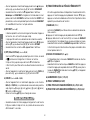
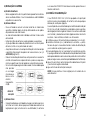
OUTPUT RADIUS PATTERN
English
c) Fixed antenna
- A fixed antenna should be installed in a clear space as possible. If it
is fixed to a mast, it will perhaps be necessary to stay it, according
to the laws in force (you should seek professional advice). All PRES-
IDENT antennas and accessories are designed to give maximum
efficiency to each CB radio within the range.

7
4) BASIC OPERATIONS TO BE CARRIED OUT BEFORE USING YOUR
SET FOR THE FIRST TIME (without transmitting and without using
the «push-to-talk» switch on the microphone)
a) Connect the microphone.
b) Check the antenna connections.
c) Turn the set on by turning the volume knob VOL (1) clockwise.
d) Turn the squelch SQ knob (3) to minimum (M position).
e) Adjust the volume to a comfortable level.
f) Go to Channel 20 using either the s/t keys (2).
5) ADJUSTMENT OF SWR (Standing wave ratio)
WARNING: This must be carried out when you use your CB radio
for the first time (and whenever you re-position your antenna). The
adjustment must be carried out in an obstacle-free area.
* Adjustment with external SWR-meter (e.g. TOS-1 PRESIDENT)
a) To connect the SWR meter :
- Connect the SWR meter between the CB radio and the antenna
as close as possible to the CB (use a maximum of 15.75 inches / 40
cm, type President CA-2C).
b) To adjust the SWR meter:
- Set the CB on channel 20.
- Put the switch on the SWR-meter to position FWD (calibration).
- Press the «push-to-talk» switch on the microphone to transmit.
- Bring the index needle to t by using the calibration key.
- Change the switch to position REF (reading of the SWR level). The
reading on the Meter should be as near as possible to 1. If this is not
the case, re-adjust your antenna to obtain a reading as close as
possible to 1. (An SWR reading between 1 and 1.8 is acceptable).
- It will be necessary to re-calibrate the SWR meter after each ad-
justment of the antenna.
WARNING: In order to avoid any losses and attenuations in cables
used for connection between the radio and its accessories, PRES-
IDENT recommends to use a cable with a length inferior to 118.11
inches / 3 m.
Your CB is now ready for use.
B) HOW TO USE YOUR CB
1) ON/OFF - VOLUME
a) To turn the set on, turn the VOL knob (1) clockwise.
If the KEY BEEP function is activated, 4 tones sound when you turn
the CB radio on.
See FUNCTIONS TURNING ON THE UNIT on page 9.
b) To increase the sound level, turn the same knob further clockwise.
2) CHANNEL SELECTOR: s/t keys ~ SCAN
CHANNEL SELECTOR
(short press)
These keys allow increasing or decreasing a channel. A «beep»
sounds each time the channel changes if the KEY BEEP function is
activated. See KEY BEEP function page 9.
SCAN (long press)
CB channel Scan
Press and hold the s (2a) or t (2b) key until a quick loop of all
the 40 channels has been done to activate the SCAN function. If
the KEY BEEP function is activated (see KEY BEEP on page 9)
A double tone sounds. “SC” appears on the display. Use s key
(2a) for increasing way or t (2b) for decreasing way. During the
scanning you can change the way by pressing the other key. The
scanning stops as soon as there is a busy channel. The scanning
automatically starts 3 seconds after the end of the transmission and
no key is activated during 3 s.
Press EMG key (5), CA/PB key (6) or PTT key (8) to deactivate the
CB channels SCAN. “SC” desappears on the display.
Weather channel Scan
Activate the WX mode (See § F - WX on page 8). Press and
hold the s (2a) or t (2b) key until a quick loop of all the 7 weather
channels has been done to activate the SCAN function. If the KEY
BEEP function is activated (see § KEY BEEP on page 9) A double
tone sounds. “SC” appears on the display. Use s key (2a) for in-
creasing way and t (2b) for decreasing way. During the scanning
EnglishEnglish

8
you can change the way by pressing the right key. The scanning
stops as soon as an alert is detected on a channel. The scanning
automatically starts 3 seconds after the end of the transmission and
no key is activated during 3 s.
Long press the CB/PA key (6) to deactivate the Weather channels
SCAN. “SC” desappears on the display.
You can let turn the weather channel SCAN in background and
return in CB mode by pressing 2 times the EMG (5) or CB/PA (6) key.
3) ASC (Automatic Squelch Control) / SQUELCH
Suppresses undesirable background noises when there is no com-
munication. Squelch does not affect neither sound nor transmission
power, but allows a considerable improvement in listening comfort.
a) ASC: AUTOMATIC SQUELCH CONTROL
Worldwide patent, a PRESIDENT exclusivity.
Turn the SQ knob (3) anti-clockwise into ASC position. «AS appears
on the display. No repetitive manual adjustment and a permanent
improvement between the sensitivity and the listening comfort
when ASC is active. This function can be disconnected by turning
the switch clockwise. In this case the squelch adjustment becomes
manual again. SC» disappears from the display.
b) MANUAL SQUELCH
Turn the SQ knob (3) clockwise to the exact point where all back-
ground noises disappear. This adjustment should be done with
precision as, if set to maximum (fully clockwise), only the strongest
signals will be received.
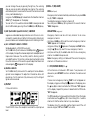
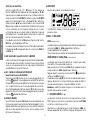
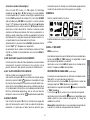
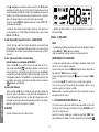
4) DISPLAY
It shows all functions:
The BARGRAPH shows the reception level and the output power
level.
5) EMG ~ F (WX/ALERT)
EMG
(short press)
Emergency channel is automatically selected when you press EMG
Key (5). “EMG” is displayed.
The default emergency channel is channel 9.
New short press in EMG key (5) to go back to the current channel.
“EMG” disappears.
EMG SETTING (long press)
Emergency channel can be set to any channel. To set a new
emergency channel :
- Short press on EMG key (5) to call the current emergency channel.
“EMG” appears on the display.
- Long press on F key (5). appears on the display and “EMG” blinks.
- Using the s/t keys (2), select the new emergency channel.
- Short press on F key (5) to validate and store the new emergency
channel. A validation beep sounds.
Notes: Emergency setting is not allowed if the current emergency
channel is not the active channel.
F - WX (WEATHER MODE) (F + s)
CB functions are not allowed in WX mode. If user presses a not
allowed key and KEY BEEP function is activated, the radio sounds
error tone.
Choose a non emergency channel. “EMG” must not appears on
the display. Long press on F key (5),
appears on the display, press
the s key (2a) in order to activate the WX mode. “WX” appears
on the display. Repeat this process to deactivate the WX mode.
“WX” disappears.
The
WX mode allows to hear weather information. When the mode
is activated, use the s/t keys (2) to move through the 7 weather
channels to find the active channel in your local area.
The display shows the selected weather channel and if the unit
receives a signal, “WX” and “ALERT” icons blink.
English

9
F - ALERT (F + t)
The SIREN tone only sounds in CB and PA mode. It does not sound
in WX mode.
Long press on F key (5), appears on the display, press the t key
(2b) in order to activate /deactivate the ALERT function. When
the function is on and a tone is detected at the selected weather
channel, then the unit sounds SIREN tone. “ALERT” and the “WX
channel” blink on the display. The unit cancel CB or PA mode and
go to WX mode.
During a SIREN tone sound, press any key to stop the sound, “ALERT”
and the WX channel stop blinking on the display.
6) CB/PA ~ NB
CB/PA
(short press)
- Press CB/PA key (6) to alternate between CB and PA (Public Ad-
dress) mode. An external loud speaker can be connected to your
ANDY USA by the PA jack plug situated on the back panel PA.SP
(D). The CB message received or transmitted into the microphone
will be directed towards the external speaker and be amplified.
Adjust the PA volume with VOL key (1).
When PA mode is activated, “PA” and “AM” blink alternatively. When
PTT switch (8) is pressed, “PA” replace the active channel on the dis-
play. Release the PTT switch (8) to display again the active channel.
NB (long press)
NOISE BLANKER. This filter allow the reduction of back ground noise,
and some reception interference. “NB” is displayed when NB filter
is active.
7) 4 PIN MICROPHONE PLUG
The plug is located on the front panel of the transceiver and makes
the setting of the equipment into the dashboard easier.
See cabling diagram page 48.
8) PTT (Push To Talk)
Transmission key, press to transmit a message, is displayed and
release to listen to an incoming communication.
See TOT function on page 10.
C) FUNCTIONS TURNING ON THE UNIT
4 more functions are available. Turn off the unit. Turn on the radio
while pressing one or two keys to set the function ON. Repeat this
action to set the function OFF.
1) ROGER BEEP (s key)
The ROGER BEEP sounds when the PTT switch (8) of the microphone
is released in order to let your correspondent speak. Historically as
CB is a “simplex” communication mode, it is not possible to speak
and listen at the same time (as it is the case with a telephone).
Once the conversation was over, he said “Roger” in order to pre-
vent his correspondent that it was his turn to talk. The word “Roger”
has been replaced by a significant beep. That is where the name
“Roger beep” comes from.
Use the following procedure to activated or deactivated the ROGER
BEEP function:
- Turn on the power while pressing the s key (2a) to enable (rb on)
or disable (rb oF) the ROGER BEEP function.
- When function is activated, “
” appears on the display.
Note: The Roger beep also sounds in the loudspeaker if the KEY
BEEP function is active. If the KEY BEEP function is not active, only
the correspondent can hear the ROGER BEEP.
In PA mode the function is not allowed.
2) KEY BEEP (t key)
Some operations such as changing channels, pressure on keys etc.
are confirmed by a beep tone. This beep tone can be activated
or deactivated as follows:
EnglishEnglish

10
- Turn on the power while pressing the t key (2b) to enable (BP on)
or disable (bP oF) the KEY BEEP function.
- When function is activated, “BP” appears on the display.
3) TOT (Time Out Timer) (CB/PA key)
If the transmission key is longer than 5 minutes, CHANNEL and ac-
tivated or deactivated
start blinking, the transmission ends.
The time-out tone will sound until the PTT key is released.
The TOT function can be activated or deactivated as follows:
- Turn on the power while pressing the CB/PA key (6) to enable (t
on) / disable (t oF) the TOT function.
4) COLOR (EMG + CB/PA keys)
- Turn on the power while pressing the EMG (5) and CB/PA (6) keys.
Symbol of the current color, among the seven, blinks, (red),
(green),
(blue), (cyan), (yellow), (purple) or (cyan
light).
- Use the s/t keys (2) to change the color.
- When the color is set, long press the F key (5). Beep sounds, the
characters of the color are displayed during 1 second.
D) FUNCTIONS WITH PTT SWITCH
2 more functions are available. To activated the function press
and hold the PTT switch (8) and press the function key. Repeat this
process to deactivate the function.
1) TALKBACK (PTT + F)
The TALKBACK function can be activated or deactivated as follows:
a) Press and hold the PTT switch (8)
b) Short press on F key (5). Current TALKBACK level blinks 3 times al-
lowing you to adjust this level.
When function is activated, “TALKBACK” appears on the display.
This function allows to ear your own modulation with the CB speaker.
2) TALKBACK LEVEL (PTT + s/t)
- At step b) adjust the TALKBACK level using the s/t keys (2) on the
unit.
- When the function in on and “TALKBACK” is shown on the display,
press and hold the PTT switch (8), then use the s/t keys (2) on the
unit. 9 levels from 01 to 09.
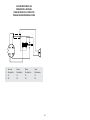
A) DC-POWER TERMINAL (13.8 V / 27.6 V)
B) ANTENNA CONNECTOR (SO-239)
C) EXTERNAL SPEAKER JACK (8 Ω, Ø 3,5 mm)
D) PA SPEAKER JACK (8 Ω, Ø 3,5 mm)
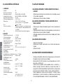
E) TECHNICAL CHARACTERISTICS
1) GENERAL
- Channels : 40
- Modulation modes : AM
- Frequency ranges : from 26.965 MHz to 27.405 MHz
- Weather channels : 162,400 MHz to 162,550 MHz
- Antenna impedance : 50 ohms
- Power supply : 13.8 V / 27.6 V
- Dimensions : 4.92 (W) x 6.89 (D) x 1.77 (H) inches
125 (W) x 175 (D) x 45 (H) mm
- Weight :
~
1.98 lbs / 0.9 kg
- Accessories supplied : Electret microphone with support,
mounting cradle, screws
- Filter : ANL (Automatic Noise Limiter) built-in
2) TRANSMISSION
- Frequency allowance : +/- 200 Hz
- Carrier power : 4 W RMS
- Transmission interference : inferior to -60 dBc
- Audio response : 300 Hz to 3 KHz
- Emitted power in the adj.
channel : inferior to 20 µW
- Microphone sensitivity : 3 mV
- Maximum drain : 1.8 A at 13.8 V / 0.9 A at 27.6 V
- Modul. signal distortion : 1.8 %
English

11
3) RECEPTION
- Maxi. sensitivity at 20
dB sinad : 0.6 µV - 111 dBm
- Frequency response : 300 Hz to 3 kHz
- Adjacent chan. selectivity : > 60 dB
- Maximum audio power : 2 W
- Squelch sensitivity : minimum 0.2 µV - 120 dBm
maximum 1 mV - 47 dBm
- Frequency image
rejection rate : 60 dB
- Intermediate frequency
rejection rate : 70 dB
- Drain : 160 ~ 500 mA (13.8 V)
50 ~ 250 mA (27.6 V)
F) TROUBLE SHOOTING
1) YOUR CB RADIO WILL NOT TRANSMIT OR YOUR
TRANSMISSION IS OF POOR QUALITY
- Check that the antenna is correctly connected and that the SWR
is properly adjusted.
- Check that the microphone is properly plugged in.
2) YOUR CB RADIO WILL NOT RECEIVE OR RECEPTION IS POOR
- Check that the squelch level is properly adjusted.
- Check that the volume is set to a comfortable listening level.
- Check that the microphone is properly plugged in.
- Check that the antenna is correctly connected and that the SWR
is properly adjusted.
3) YOUR CB WILL NOT LIGHT UP
- Check the power supply.
- Check the connection wiring.
- Check the fuse.
G) HOW TO TRANSMIT OR RECEIVE A MESSAGE
Now that you have read the manual, make sure that your CB Radio
is ready for use (i.e. check that your antenna is connected).
Press the «push-to-talk» switch (8) and announce your message «At-
tention stations, transmission testing» which will allow you to check
the clearness and the power of your signal. Release the switch and
wait for a reply. You should receive a reply like, «Strong and clear».
If you use a calling channel (19) and you have established commu-
nication with someone, it is common practice to choose another
available channel so as not to block the calling channel.
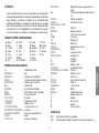
H) GLOSSARY
Below you will find some of the most frequently used CB radio ex-
pressions. Remember this is meant for fun and that you are by no
means obliged to use them. In an emergency, you should be as
clear as possible.
INTERNATIONAL PHONETIC ALPHABET
A Alpha H Hotel O Oscar V Victor
B Bravo I India P Papa W Whiskey
C Charlie J Juliett Q Quebec X X-ray
D Delta K Kilo R Romeo Y Yankee
E Echo L Lima S Sierra Z Zulu
F Foxtrott M Mike T Tango
G Golf N November U Uniform
TECHNICAL VOCABULARY
AM : Amplitude Modulation
CB : Citizen’s Band
CH : Channel
CW : Continuous Wave
DX : Long Distance Liaison
DW : Dual Watch
FM : Frequency Modulation
GMT : Greenwich Meantime
EnglishEnglish

12
HF : High Frequency
LF : Low Frequency
LSB : Lower Side Band
RX : Receiver
SSB : Single Side Band
SWR : Standing Wave Ratio
SWL : Short Wave Listening
SW : Short Wave
TX : CB Transceiver
UHF : Ultra High Frequency
USB : Upper Side Band
VHF : Very High Frequency
CB LANGUAGE
Advertising : Flashing lights of police car
Back off : Slow down
Basement : Channel 1
Base station : A CB set in fixed location
Bear : Policeman
Bear bite : Speeding fine
Bear cage : Police station
Big slab : Motorway
Big 10-4 : Absolutely
Bleeding : Signal from an adjacent channel
interfering with the transmission
Blocking the channel : Pressing the PTT switch without talking
Blue boys : Police
Break : Used to ask permission to join a
conversation
Breaker : A CBer wishing to join a channel
Clean and green : Clear of police
Cleaner channel : Channel with less interference
Coming in loud and proud : Good reception
Doughnut : Tyre
Down and gone : Turning CB off
Down one : Go to a lower channel
Do you copy? : Understand?
DX : Long distance
English
Eighty eights : Love and kisses
Eye ball : CBers meeting together
Good buddy : Fellow CBer
Hammer : Accelerator
Handle : CBer’s nickname
Harvey wall banger : Dangerous driver
How am I hitting you? : How are you receiving me?
Keying the mike : Pressing the PTT switch without talking
Kojac with a kodak : Police radar
Land line : Telephone
Lunch box : CB set
Man with a gun : Police radar
Mayday : SOS
Meat wagon : Ambulance
Midnight shopper : Thief
Modulation : Conversation
Negative copy : No reply
Over your shoulder : Right behind you
Part your hair : Behave yourself - police ahead
Pull your hammer back : Slow down
Rat race : Congested traffic
Rubberbander : New CBer
Sail boat fuel : Wind
Smokey dozing : Parked police car
Smokey with a camera : Police radar
Spaghetti bowl : Interchange
Stinger : Antenna
Turkey : Dumb CBer
Up one : Go up one channel
Wall to wall : All over/everywhere
What am I putting to you? : Please give me an S-meter reading

13
GENERAL WARRANTY CONDITIONS
This device is guaranteed 2 years parts and labour in its country of purchase
against any manufacturing defects validated by our technical department. PRES-
IDENT After Sales Service department reserves the right not to apply the warranty
in the event a breakdown is caused by an antenna other than those distributed by
PRESIDENT. An extension of 3 years warranty is proposed systematically for the
simultaneous purchase of a device and a PRESIDENT antenna, bringing the total
duration of the warranty to 5 years. In order to be valid, the warranty registration
must be completed and submitted within a period of 30 days after the purchase
date to PRESIDENT ELECTRONICS online at
www.president-electronics.
us/warranty-registration
. You can also access this warranty registration page
by using your smartphone to read (application must be available) the QR code on
the enclosed warranty card. You will receive a confirmation email if the registration
is successfully completed. Please keep a copy of this email for your records.
Any repair under warranty will be without charge and the return delivery costs will
be borne by PRESIDENT. A proof of purchase sales receipt must be included with
the device to be repaired. The dates listed on the warranty registration and proof
of purchase must match. In case the device is not under warranty, the repair and
return of the device will be charged.
No spare parts will be sent nor exchanged by PRESIDENT under warranty. Do
not proceed with the installation of the device without reading the user manual.
The warranty is only valid in the country of purchase.
Exclusions (not covered by Warranty):
• Damages caused by accident, shock or inadequate packaging.
• Power transistors, microphones, lights, fuses and the disrespect of the instal-
lation and use of specifications (including but not limited to antenna used with
too high power, final output power transistors (SWR), inversion of polarities, bad
connections, over voltage…).
• The warranty cannot be extended due to the non-availability of the device while
it is being serviced at PRESIDENT After Sales Service department, nor by a
change of one or more components or spare parts.
• Transceivers which have been modified. The warranty application is excluded
in case of modification or poor maintenance done by a third party not approved
by PRESIDENT ELECTRONICS.
If you note a malfunction:
• Check the power supply of your device and the quality of the fuse.
• Check that the antenna, the microphone are correctly connected.
• Check that the squelch level is properly adjusted; the programmed configuration
is the correct one.
• In the event of a real malfunction, please contact your dealer first. He will decide
what action should be taken.
In case of an intervention not covered by warranty, an estimate will be established
before any repair.
Thank you for your confidence in the PRESIDENT quality and experience. We
recommend that you read this manual carefully so that you are completely satisfied
with your purchase.
Technical Manager
and
Quality Manager
EnglishEnglish

14
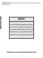
ATTENTION !
Avant toute utilisation, prenez garde de ne jamais émettre
sans avoir branché l’antenne (connecteur B situé sur la
face arrière de l’appareil), ni réglé le TOS (Taux d’Ondes
Stationnaires)! Sinon, vous risquez de détruire l’amplifica-
teur de puissance, ce qui n’est pas couvert par la garantie.
FrançaisFrançais
La garantie de ce poste est valable uniquement dans le pays d’achat.
AVERTISSEMENT PROPOSITION 65: Ce produit contient un produit chimique connu dans l’État de Californie pour provoquer des cancers et des malformations congénitales ou
d’autres problèmes de reproduction.

15
Bienvenue dans le monde des émetteurs-récepteurs CB de la
dernière génération. Cette nouvelle gamme de postes vous fait
accéder à la communication électronique la plus performante.
Grâce à l’utilisation de technologies de pointe garantissant
des qualités sans précédent, votre PRESIDENT ANDY USA 12/24
V est un nouveau jalon dans la convivialité et la solution par
excellence pour le pro de la CB le plus exigeant. Pour tirer le
meilleur parti de toutes ses possibilités, nous vous conseillons
de lire attentivement ce mode d’emploi avant d’installer et
d’utiliser votre CB PRESIDENT ANDY USA 12/24 V.
A) INSTALLATION
1) CHOIX DE L’EMPLACEMENT, MONTAGE DU POSTE MOBILE
a) Choisissez l’emplacement le plus approprié à une utilisation simple
et pratique de votre poste mobile.
b) Veillez à ce qu’il ne gêne pas le conducteur ni les passagers du
véhicule.
c) Prévoyez le passage et la protection des différents câbles, (alimen-
tation, antenne, accessoires...) afin qu’ils ne viennent en aucun cas
perturber la conduite du véhicule.
d) Utilisez pour le montage le berceau (1) livré avec l’appareil, fixez-le
solidement à l’aide des vis auto taraudeuse (2) fournies (diamètre
de perçage 3,2 mm). Prenez garde de ne pas endommager le
système électrique du véhicule lors du perçage.
e) Lors du montage, n’oubliez pas d’insérer les rondelles de caout-
chouc (3) entre le poste et son support. Celles-ci jouent en effet
un rôle «d’amortisseur» et permettent une orientation et un serrage
en douceur du poste.
f) Choisissez un emplacement pour le support du micro et prévoyez
le passage de son cordon.
- NOTE : Votre poste mobile possédant une prise micro en façade
peut être encastré dans le tableau de bord. Dans ce cas, il est
recommandé d’y adjoindre un haut-parleur externe pour une
meilleure écoute des communications (connecteur EXT.SP situé sur
la face arrière de l’appareil : C). Renseignez-vous auprès de votre
revendeur le plus proche pour le montage sur votre appareil.
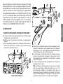
SCHÉMA GÉNÉRAL DE MONTAGE
Français

16
2) INSTALLATION DE L’ANTENNE
a) Choix de l’antenne :
- En CB, plus une antenne est grande, meilleur est son rendement.
Votre Point Conseil saura orienter votre choix.
b) Antenne mobile :
- Il faut l’installer à un endroit du véhicule où il y a un maximum de
surface métallique (plan de masse), en s’éloignant des montants
du pare-brise et de la lunette arrière.
- Dans le cas où une antenne radiotéléphone est déjà installée,
l’antenne CB doit être au-dessus de celle-ci.
- Il existe 2 types d’antennes : les préréglées et les réglables.
- Les préréglées s’utilisent de préférence avec un bon plan de masse
(pavillon de toit ou malle arrière).
- Les réglables offrent une plage d’utilisation beaucoup plus large
et permettent de tirer parti de plans de masse moins importants
(voir § 5 page 17 RÉGLAGE DU TOS).
- Pour une antenne à fixation par perçage, il est nécessaire d’avoir
un excellent contact antenne/plan de masse ; pour cela, grattez
légèrement la tôle au niveau de la vis et de l’étoile de serrage.
- Lors du passage du câble coaxial, prenez garde de ne pas le pincer
ou l’écraser (risque de rupture ou de court-circuit).
- Branchez l’antenne (B).
antennes et accessoires que nous distribuons sont spécialement
conçus pour un rendement optimal de chaque appareil de la
gamme.
3) CONNEXION DE L’ALIMENTATION
Votre PRESIDENT ANDY USA 12/24 V est muni d’une protection contre
les inversions de polarité. Néanmoins, avant tout branchement,
vérifiez vos connexions.
Votre poste doit être alimenté par une source de courant continu
de 12 ou 24 Volts (A). À l’heure actuelle, la plupart des voitures et
des camions fonctionnent avec une mise à la masse négative. On
peut s’en assurer en vérifiant que la borne (-) de la batterie soit bien
connectée au bloc moteur ou au châssis. Dans le cas contraire,
consultez votre revendeur.
a) Assurez-vous que l’alimentation soit bien de 12 ou 24 Volts.
b) Repérez les bornes (+) et (-) de la batterie (+ = rouge, - = noir). Dans
le cas où il serait nécessaire de rallonger le cordon d’alimentation,
utilisez un câble de section équivalente ou supérieure.
c) Il est nécessaire de se connecter sur un (+) et un (-) permanents.
Nous vous conseillons donc de brancher directement le cordon
d’alimentation sur la batterie (le branchement sur le cordon de
l’autoradio ou sur d’autres parties du circuit électrique pouvant
dans certains cas favoriser la réception de signaux parasites).
d) Branchez le fil rouge (+) à la borne positive de la batterie et le fil
noir (-) à la borne négative de la batterie.
e) Branchez le cordon d’alimentation au poste.
ATTENTION : Ne jamais remplacer le fusible d’origine par un modèle
d’une valeur différente !
LOBE DE RAYONNEMENT
FrançaisFrançais
c) Antenne fixe :
- Veillez à ce qu’elle soit dégagée au maximum. En cas de fixation
sur un mât, il faudra éventuellement haubaner conformément aux
normes en vigueur (se renseigner auprès d’un professionnel). Les

17
4) OPÉRATIONS DE BASE À EFFECTUER AVANT LA PREMIÈRE
UTILISATION, SANS PASSER EN ÉMISSION (c’est-à-dire sans
appuyer sur la pédale du micro)
a) Branchez le micro,
b) Vérifiez le branchement de l’antenne,
c) Mise en marche de l’appareil : tourner le bouton du volume VOL
(1) dans le sens des aiguilles d’une montre,
d) Tournez le bouton du squelch SQ (3) au minimum (dans le sens
inverse des aiguilles d’une montre) en position M,
e) Réglez le volume à un niveau convenable,
f) Amenez le poste sur le canal 20 à l’aide des touches s/t (2).
5) RÉGLAGE DU TOS (Taux d’ondes stationnaires)
ATTENTION : Opération à effectuer impérativement lors de la pre-
mière utilisation de l’appareil ou lors d’un changement d’antenne.
Ce réglage doit être fait dans un endroit dégagé, à l’air libre.
* Réglage avec TOS-mètre externe (type TOS-1 PRESIDENT)
a) Branchement du Tos-mètre :
- Brancher le Tos-mètre entre le poste et l’antenne, le plus près pos-
sible du poste (utiliser pour cela un câble de 40 cm (15,75 pouces)
maximum type CA-2C PRESIDENT).
b) Réglage du Tos :
- Amener le poste sur le canal 20.
- Positionner le commutateur du Tos-mètre en position FWD (ca-
librage).
- Appuyer sur la pédale PTT (8) pour passer en émission.
- Amener l’aiguille sur l’index t à l’aide du bouton de calibrage.
- Basculer le commutateur en position REF (lecture de la valeur du
TOS). La valeur lue sur le vu-mètre doit être très proche de 1. Dans
le cas contraire, rajuster votre antenne jusqu’à obtention d’une
valeur aussi proche que possible de 1 (une valeur de TOS comprise
entre 1 et 1,8 est acceptable).
- Il est nécessaire de recalibrer le Tos-mètre, entre chaque opération
de réglage de l’antenne.
Remarque : Afin d’éviter les pertes et atténuations dans les câbles
de connexion entre la radio et ses accessoires, PRESIDENT recom-
mande une longueur de câble inférieure à 118.11 pouces (3 m).
Maintenant, votre poste est prêt à fonctionner.
B) UTILISATION
1) MARCHE/ARRÊT - VOLUME
a) Pour allumer votre poste, tourner le bouton VOL (1) dans le sens
des aiguilles d’une montre. Si la fonction KEY BEEP est activée, 4
notes sont émises à la mise en marche.
Voir le § FONCTIONS À L’ALLUMAGE DE L’APPAREIL page 19.
b) Pour augmenter le volume sonore, continuer à tourner ce bouton
dans le sens des aiguilles d’une montre.
2) SÉLECTEUR DE CANAUX : touches s/t ~ SCAN
SÉLECTEUR DE CANAUX
(pression brève)
Ces touches permettent d’effectuer une montée ou une descente
des canaux. Un bip est émis à chaque changement de canal si la
fonction KEY BEEP est activée. Voir fonction KEY BEEP page 20.
SCAN (pression longue)
Scan des canaux CB
Pour activer la fonction SCAN, maintenir appuyée la touche s (2a)
ou t (2b) jusqu’à ce qu’une rapide boucle de tous les canaux soit
effectuée. Si la fonction KEY BEEP est activée (voir fonction KEY BEEP
page 20) un bouble bip est émis. «SC» apparaît dans l’afficheur.
Utiliser la touche s (2a) pour scanner dans le sens croissant et
t (2b) pour scanner dans le sens décroissant. Pendant le scan,
presser l’une ou l’autre des ces touches pour changer de sens. Le
scan est interrompu dès qu’il rencontre un canal actif. Il reprend
automatiquement 3 secondes après la transmission ou si aucune
touche n’est pressée pendant 3 secondes.
Pour désactiver la fonction SCAN presser une des touches suivantes,
EMG (5), CB/PA (6) ou PTT (8). «SC» disparait de l’afficheur.
Français

18
SCAN des canaux Météo
Activer le mode WX (voir § F - WX page 18). Pour activer la
fonction SCAN, maintenir appuyée la touche s (2a) ou t (2b)
jusqu’à ce qu’une rapide boucle de tous les 7 canaux météo soit
effectuée. Si la fonction KEY BEEP est activée (voir fonction KEY BEEP
page 20) un bouble bip est émis. «SC» apparaît dans l’afficheur.
Utiliser la touche s (2a) pour scanner dans le sens croissant et t
(2b) pour scanner dans le sens décroissant. Pendant le scan, presser
l’une ou l’autre des ces touches pour changer de sens. Le scan
est interrompu dès qu’une alerte météo est détectée. Il reprend
automatiquement 3 secondes après la transmission ou si aucune
touche n’est pressée pendant 3 secondes.
Pour désactiver la fonction SCAN presser longuement la touche
CB/PA (6). «SC» disparait de l’afficheur.
Le scan des canaux météo peut tourner en tâche de fond pendant
l’utilisation de la CB en appuyant deux fois sur la touche EMG (5)
ou CB/PA (6).
3) ASC (Automatic Squelch Control) / SQUELCH
Cette fonction permet de supprimer les bruits de fond indésirables
en l’absence de communication. Le squelch ne joue ni sur le volume
sonore ni sur la puissance d’émission, mais il permet d’améliorer
considérablement le confort d’écoute.
a) ASC : SQUELCH A RÉGLAGE AUTOMATIQUE
Brevet mondial, exclusivité PRESIDENT
Tourner le bouton SQ (3) dans le sens inverse des aiguilles d’une
montre. ASC apparaît. Aucun réglage manuel répétitif et optimisa-
tion permanente entre la sensibilité et le confort d’écoute lorsque
l’ASC est actif (à fond en sens inverse des aiguilles d’une montre).
Elle est débrayable par rotation du bouton SQ (3) dans le sens des
aiguilles d’une montre. Dans ce cas le réglage du squelch redevient
manuel. ASC disparaît de l’afficheur.
b) SQUELCH MANUEL
Tournez le bouton du squelch SQ (3) dans le sens des aiguilles d’une
montre jusqu’au point exact où tout bruit de fond disparaît. C’est un
réglage à effectuer avec précision, car mis en position maximum
dans le sens des aiguilles d’une montre, seuls les signaux les plus
forts peuvent être perçus.
4) AFFICHEUR
Il permet de visualiser l’ensemble des fonctions :
Le BARGRAPH visualise le niveau de réception et le niveau de
puissance émise.
5) EMG ~ F (WX/ALERT)
EMG
(pression brève)
Le canal d’urgence est automatiquement sélectionné en appuyant
sur la touche EMG (5). «EMG» apparaît dans l’afficheur.
Le canal par défaut est le canal 9.
Une nouvelle pression ramène au canal précédemment utilisé.
REDÉFINITION DU CANAL EMG (pression longue)
Le canal d’urgence peut être affecter à n’importe quel canal.
Pour définir un nouveau canal d’urgence :
- Appuyer brièvement sur la touche EMG (5) pour appeler le canal
d’urgence actuel. «EMG» apparaît dans l’afficheur.
- Appuyer durant 2 secondes sur la touche F (5). apparaît dans
l’afficheur et «EMG» clignote.
- À l’aide des es touches s/t (2), choisir le nouveau canal d’urgence.
- Appuyer brièvement sur la touche F (5) pour valider et définir le
nouveau canal d’urgence. Un bip de validation est émis.
Remarque : redéfinir le canal d’urgence n’est possible que si le
canal d’urgence actuel est actif.
F - WX (MODE MÉTÉO) (F + s)
Les fonctions courantes de la CB ne sont pas permises en mode
WX. À l’appui sur une touche non autorisée, si la fonction KEY BEEP
est active, un bip d’erreur est émis.
Sélectionner un canal autre que le canal d’urgence. «EMG» ne
dois pas apparaître dans l’afficheur. Appuyer longuement sur la
FrançaisFrançais

19
touche F (5), apparaît dans l’afficheur, appuyer sur la touche
s (2a) pour activer le mode WX. «WX» s’affiche. Répéter cette
procédure pour désactiver ce mode. «WX» disparaît.
Le mode
WX permet d’écouter des bulletins d’information mé-
téorologique. Quand ce mode est activé, utiliser les touches s/t
(2) pour rechercher parmi des 7 canaux météorologiques le canal
correspondant à votre localisation.
L’afficheur indique le canal choisi et, si un signal météo est reçu,
«WX» et «ALERT» clignotent.
F - ALERT (F + t)
La sirène d’alerte ne se déclenche que dans les mode PA ou CB.
Elle ne fonctionne pas en mode WX.
Appuyer longuement sur la touche F (5), apparaît dans l’afficheur,
appuyer sur la touche t (2b) pour activer/désactiver la fonction.
Quand la fonction est active et qu’un signal est détecté dans la
canal météo actif, l’appareil émet une alerte «SIRÈNE». «ALERT» et
le canal météo actif clignotent dans l’afficheur. L’appareil annule
le mode CB ou PA pour passer en mode WX.
Durant la sirène d’alerte, appuyer sur n’importe quelle touche pour
arrêter le son. «ALERT» et le canal météo actif cessent de clignoter.
6) CB/PA ~ NB
CB/PA
(pression brève)
- Appuyer sur la touche CB/PA (6) pour alterner entre les mode CB
et PA (Public Address). Un haut-parleur de sonorisation extérieure
peut être connecté sur le poste par une prise jack située sur le
panneau arrière PA.SP. (D). Les messages CB reçus et émis via le
microphone seront dirigés et amplifiés vers le haut-parleur externe
du PA. Le bouton du volume VOL (1) permet de régler le niveau
de volume du PA.
En mode PA, «PA» et «AM» clignotent alternativement. Quand la
pédale d’émission PTT (8) est appuyée «PA» s’affiche à la place
du canal actif. Relâcher la pédale PTT (8) et l’affichage revient au
canal actif.
NB (pression longue)
NOISE BLANKER. Ce filtre permet de réduire les bruits de fonds et de
supprimer le bruit d’allumage à la réception. «NB» apparaît dans
l’afficheur quand le filtre NB est activé.
7) PRISE MICRO 4 BROCHES
Elle se situe en façade de votre appareil et facilite ainsi son inté-
gration à bord de votre véhicule.
Voir schéma de branchement en page 48.
8) PTT (Push To Talk)
Pédale d’émission, appuyer pour parler,
s’affiche. Relâcher
pour recevoir un message.
Voir fonction TOT page 20.
C) FONCTIONS À L’ALLUMAGE DE L’APPAREIL
4 fonctions supplémentaires sont disponibles. Pour activer la fonction,
éteindre le poste, rallumer le poste en maintenant une ou deux
touches appuyées. Répéter la même opération pour désactiver
la fonction.
1) ROGER BEEP (touche s)
Le ROGER BEEP est émis quand la pédale d’émission PTT (8) est
relâchée afin de prévenir votre interlocuteur que vous avez termi-
ner et lui laisser la parole. Historiquement, la CB étant un mode de
communication «simplex», c’est-à-dire qu’il n’est pas possible de
parler et d’écouter en même temps (comme c’est le cas pour le
téléphone par exemple), il était d’usage de dire «Roger» une fois
que l’on avait fini de parler afin de prévenir son correspondant
qu’il pouvait parler à son tour. Le mot «Roger» a été remplacé par
un bip significatif, d’où son nom “Roger Beep”.
Cette fonction peut être activer ou désactiver de la manière sui-
vante :
Français

20
- Allumer l’appareil en maintenant appuyée la touche s (2a) pour
activer (rb on) ou désactiver (rb oF) la fonction ROGER BEEP.
- Quand la fonction est active “ ” apparaît dans l’afficheur.
Remarque : Le ROGER BEEP est également entendu dans le haut-
parleur si la fonction KEY BEEP est activée. Si la fonction KEY BP n’est
pas activée, seul le correspondant peut entendre le ROGER BEEP.
En mode PA cette fonction n’est pas autorisée.
2) KEY BEEP (touche t)
Certaines opérations comme le changement de canal, l’appui sur
les touches, etc. sont confirmées par un bip.
Ce bip peut être activer ou désactiver de la manière suivante :
- Allumer l’appareil en maintenant appuyée la touche t (2b) pour
activer (bP on) ou désactiver (bP oF) la fonction KEY BEEP.
- Quand la fonction est active «BP» apparaît dans l’afficheur.
3) TOT (Time Out Timer) (touche CB/PA)
Si la touche PTT est appuyée pendant plus de 5 minutes, le canal
et commencent à clignoter et l’émission se termine.
Un bip est émis jusqu’à ce que la touche PTT soit relâchée.
Cette fonction peut être activer ou désactiver de la manière sui-
vante :
- Allumer l’appareil en maintenant appuyée la touche CB/PA (6)
pour activer (t on) ou désactiver (t oF) la fonction TOT.
4) COLOR (touches EMG + CB/PA)
- Allumer l’appareil tout en maintenant appuyées sur les touches
EMG (5) et CB/PA (6). Le symbole de la couleur actuelle, parmi les
sept, clignote,
(rouge), (vert), (bleu), (cyan), (jaune),
(violet) ou (bleu clair).
- Utiliser les touches s/t (2) pour changer la couleur.
- Quand la couleur est choisie, appuyer longuement sur la touche
F (5) pour valider. Un bip est émis, le symbole de la couleur reste
affiché durant 1 seconde.
D) FONCTIONS AVEC LA PÉDALE D’ÉMISSION PTT
2 fonctions supplémentaires sont disponibles. Pour activer la fonction,
appuyer et maintenir appuyée la pédale d’émission PTT (8) puis,
appuyer sur la touche dédiée à cette fonction. Répéter la même
opération pour désactiver la fonction.
1) TALKBACK (PTT + F)
La fonction TALKBACK peut être activée ou désactivée de la ma-
nière suivante :
a) Appuyer et maintenir appuyée la pédale d’émission PTT (8).
b) Appuyer brièvement sur la touche F (5). Le niveau du TALKBACK
actuel clignote 3 fois indiquant que vous pouvez régler ce niveau.
Quand la fonction est active, «TALKBACK» apparaît dans l’afficheur.
Cette fonction permet d’entendre votre propre modulation dans
le haut-parleur de la CB.
2) NIVEAU DU TALKBACK (PTT + s/t)
- À l’étape b), ajuster le niveau du TALKBACK à l’aide des touches
s/t (2)sur l’appareil.
- Quand la fonction est active et que «TALBACK» est affiché, appuyer
et maintenir appuyée la pédale d’émission PTT (8) puis ajuster le
niveau du TALKBACK à l’aide des touches s/t (2) sur l’appareil.
9 niveaux de 01 à 09.
A) ALIMENTATION (13,8 V / 27,6 V)
B) PRISE D’ANTENNE (SO-239)
C) PRISE POUR HAUT-PARLEUR EXTÉRIEUR (8 Ω, Ø 3,5 mm)
D) PRISE POUR HAUT-PARLEUR PA EXTÉRIEUR (8 Ω, Ø 3,5 mm)
FrançaisFrançais
A página está carregando...
A página está carregando...
A página está carregando...
A página está carregando...
A página está carregando...
A página está carregando...
A página está carregando...
A página está carregando...
A página está carregando...
A página está carregando...
A página está carregando...
A página está carregando...
A página está carregando...
A página está carregando...
A página está carregando...
A página está carregando...
A página está carregando...
A página está carregando...
A página está carregando...
A página está carregando...
A página está carregando...
A página está carregando...
A página está carregando...
A página está carregando...
A página está carregando...
A página está carregando...
A página está carregando...
A página está carregando...
A página está carregando...
A página está carregando...
A página está carregando...
A página está carregando...
-
 1
1
-
 2
2
-
 3
3
-
 4
4
-
 5
5
-
 6
6
-
 7
7
-
 8
8
-
 9
9
-
 10
10
-
 11
11
-
 12
12
-
 13
13
-
 14
14
-
 15
15
-
 16
16
-
 17
17
-
 18
18
-
 19
19
-
 20
20
-
 21
21
-
 22
22
-
 23
23
-
 24
24
-
 25
25
-
 26
26
-
 27
27
-
 28
28
-
 29
29
-
 30
30
-
 31
31
-
 32
32
-
 33
33
-
 34
34
-
 35
35
-
 36
36
-
 37
37
-
 38
38
-
 39
39
-
 40
40
-
 41
41
-
 42
42
-
 43
43
-
 44
44
-
 45
45
-
 46
46
-
 47
47
-
 48
48
-
 49
49
-
 50
50
-
 51
51
-
 52
52


PRESIDENT Andy USA Manual do proprietário
- Tipo
- Manual do proprietário
em outras línguas
Artigos relacionados
-
PRESIDENT MC KINLEY USA 12/24 V Manual do proprietário
-
-
-
-
PRESIDENT JOHNSON II Manual do proprietário
-
-
-
PRESIDENT MC-KINLEY-USA Manual do proprietário
-
PRESIDENT Ronald 12M Manual do proprietário
-
Outros documentos
-
Sirio Antenne CARBONIUM 27SUPER CARBONIUM 27 Manual do usuário
-
Midland 200 Manual do usuário
-
Motorola NNTN4846 Manual do proprietário
-
-
 Welch Allyn Tycos Harvey Original Double Head Manual do usuário
-
Welch Allyn Tycos Harvey Original Double Head Manual do usuário
