GCE TERMINAL UNITS MINI Instruções de operação
- Tipo
- Instruções de operação

GCE HEALTHCARE
EN
TERMINAL UNITS MINI
TERMINAL UNIT
GASUTTAG
TOMADA
TERMINÁLNÍ JEDNOTKA
TERMINÁLEGYSÉG
SV
PT
INSTRUCTION FOR USE
BRUKSANVISNING
INSTRUÇÕES DE UTILIZAÇÃO
NÁVOD K POUŽITÍ
HASZNÁLATI ÚTMUTATÓ
CS
HU

2/60
EN
1. FOREWORD
GCE Terminal units (“TU”) are medical devices classifi ed according to the
Directive concerning medical devices
(93/42/EEC – MDD 2007/47/EC).
Conformity with essential requirements of the Directive 93/42/EEC – MDD
2007/47/EC is on the basis of the EN ISO 9170-1 standard.
2. INTENDED USE
TU are intended to be used as outlet points at hospital low pressure
gas supply system. TU is an outlet point where operators connect and
disconnect an inlet of other gas specifi ed medical devices, such as
medical hoses, fl owmeters,etc.
The TU are designed to be gas specifi c which means that they cannot be
connected to a medical device that is for a di erent type of gas.
TU cannot be placed into operation before these instructions are
thoroughly read and understood.
Operator of TU must be properly trained for such operation - see
chapter4.
BASIC VARIANTS OF TU DIVISION ACCORDING TO THE GAS:
• Oxygen (O2)
• Medical air (AIR)
• Laughing gas (nitrous oxide)
(N2O)
• Carbon dioxide (CO2)
• mixtures of the specifi ed gases
(e.g. O2+N2O)
• Underpressure (Vacuum)(VAC)
• Nitrogen (N2)
ENGLISH
INSTRUCTION FOR USE: TU MINI

3/60
EN
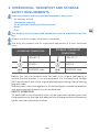
3. OPERATIONAL, TRANSPORT AND STORAGE
SAFETY REQUIREMENTS
Keep the product and its associated equipment away from:
• All sources of heat
• Flammable materials
• Oil or grease (including all hand creams)
• Water
• Dust.
The product and its associated equipment must be prevented from fall-
ing.
Always maintain oxygen cleanliness standards.
Use only the product and its associated equipment in a well ventilated
area.
OPERATING CONDITIONS STORAGE, TRANSPORT
CONDITIONS
-20/+60 °C -30/+70 °C
10/100% 20/70%
600/1200 mbar 600/1200 mbar
Before fi rst use the product must be kept in its original packaging to
ensure that the product is not contaminated. For transport and storage
GCE recommends use of the original packaging (including internal sealing
bag and caps).
Statutory laws, rules and regulations for medical gases, accident prevention
and environmental protection must be observed.
SAFETY OPERATION
TU described in this document must only be used with medical gases and
the procedures for the safe and e ective use of these medical compressed
gases must be followed at all times.

4/60
EN
4. PERSONNEL INSTRUCTIONS
The Medical Devices Directive 93/42/EEC states that product provider
must ensure that all personnel handling the product are provided with the
operating instructions & performance data.
Do not use the product without properly familiarization of the product
and its safe operation as defi ned in this Instruction for use. Ensure user
is aware of particular information and knowledge required for the gas
in use.
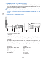
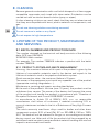
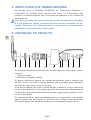
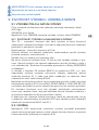
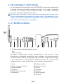
5. PRODUCT DESCRIPTION
101211798
13
654321
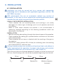
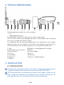
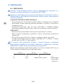
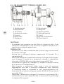
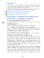
TU consist of two basic parts:
• housing
• quick connection valve
Individual parts must always be designed as gas specifi c. Each of these
basic parts is marked with stamping displaying the gas for which it is
intended.
An integral part of each terminal unit is a check valve enabling the
through-pass of the gas when a counterpart is connected and which
automatically prevents the gas from passing through when the counterpart
is disconnected.
1) Housing
2) Sealing for service valve
3 Maintenance valve
4) O-ring
5) Locking nipple
6) Valve case
7) Label
8) Exposed cover
9) Screw
10) Dust plug
11) Sleeve
12) Circlip
13) Body QC

5/60
EN
6. INSTALLATION
6.1. INSTALLATION
Installation can only be carried out by a person with appropriate
knowledge and in accordance with applicable regulations and the EN
ISO 7396-1 standard.
GCE recommends the use of accessories without any content of
phtalates, in the case of use of accessories containing phtalates please
consider the risks which may result from them for patients.
VISUAL CHECK BEFORE INSTALLATION
• Check whether the unit (including labels and marking) is not visibly
damaged. If it states signs of damage, put it out of operation and mark
its condition.
• Make a visual check whether the product is not contaminated; if
necessary proceed according to the cleaning procedures which are
described in this Manual.
INSTALLATION
• Before assembly please blow through the internal space of the pipeline.
• Check whether the sealing (2) is present before installation of the check
valve subassembly.
• Check whether the unit case is identical with the marking of the gas on
the pipeline.
• Use a silver solder (at least 40% of silver) for soldering, with a low melting
point (about 600°C), cadmium-free.
During assembly always use suitable and functional tools and adhere to
safety requirements for operation, transport and storage, and maintain
appropriate cleanliness of the terminal unit. (see Chapter 3).
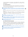
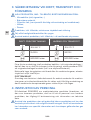
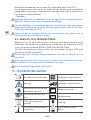
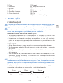
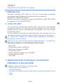
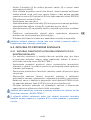
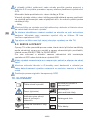
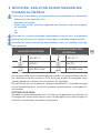
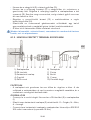
The minimum inter-axis distance between 2 sockets must be a minimum of
100 mm; the following order should be respected beginning from the left.
10 cm 10 cm 10 cm
1 2 3 4
O2 N2O Medical Air Medical aspirator
(vacuum)

6/60
EN
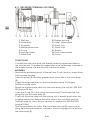
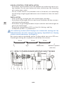
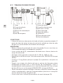
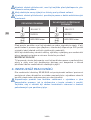
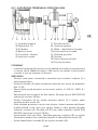
6.1.1. RECESSED TERMINAL UNIT MINI
1 2 3 4 5 6 7 8 9 10 11 12 13 14
1) Wall box
2) Valve body
3 Al gasket
4) Maintenance valve
5) O-ring
6) Locking nipple
7) Valve case
8) Rubber bushing
9) Label - Name plate
10) Cover ring
11) Plastic cup
12) Screws
13) Push-release plate
14) Circlip
CONDITIONS
• The wall box and valve body are already carefully aligned and fi xed in
the fi nished wall. The piece of copper tube in the valve body is brazed to
the proper service line and the joint is tested for leaks.
ASSEMBLY
• Remove the protecting cover of the wall box (1 ) wíth knife or screw driver
and unscrew the plug.
• lnsert Al gasket (3) smoothly greased with silicon and in the valve body
(2).
• Check the engraved letter on the maintenance valve: O=Oxygen,
N=Nitrous oxide, A=Air.
• Screw the maintenance valve into the valve body. Use tool No. 202 200
514 (torque 12 Nm).
• lnsert the O-ring (5) in the slot of the valve case (7) and screw the cou-
pling fully into the valve body (2).
• Then turn the valve case until the locking slot is exactly plumb over the
coupling centre line. Secure the valve case in the is position with the
locking nipple (6). Use a 24 mm spanner or special tool 202 200 513,
(torque 15 Nm).
• Test the connection for leaks. Slip the rubber bushing (8) over the cou-
pling, bevelled end outwards, and press the bushing against the base of
the valve body (2).

7/60
EN
• lnsert the name ring (9) in the cover ring (10).
• lnsert the plastic cup (11} in the name ring and slip it over the bushing.
Fasten the plastic cup in the valve body with the two screws (12). Tighten
the screws until the cover ring rests closely against the wall.
• Fasten the push-release plate (13) to the coupling with the cir-clip (14).
• Test the function of the assembled gas outlets by connecting a male
quick coupling for the respective gas.
• Reject enclosed details intended for exposed assembly.
Keep all equipment, also hands, tools, working clothes clean and free
from grease or oil.
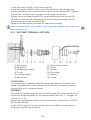
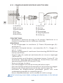
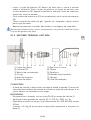
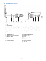
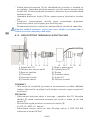
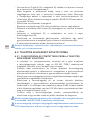
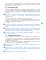
6.1.2. EXPOSED TERMINAL UNIT MINI
108 116 9
54321 712
1) Valve body
2) PA gasket
3 Maintenance valve
4) O-ring
5) Locking nipple
6) Valve case
7) Label - Name plate
8) Cover
9) Screws
10) Dust plug
11) Sleeve
12) Circlip
CONDITIONS
• The valve body is already carefully aligned and fi xed on the wall. The
piece of copper tube in the valve body is brazed to the proper service
line and the joint is tested for leaks.
ASSEMBLY
• Unscrew the tightening plug. Insert the PA gasket (2) in the valve body (1).
• Check the engraved letter on the maintenance valve (3): O = Oxygen; N
= Nitrous; A = Air
• Screw the maintenance valve into the valve body. Use tool No. 202 200
514 (torque 12 Nm).
• Insert the O-ring (4) in the slot of the valve case (6) and screw the cou-
pling fully into the valve body (1).

8/60
EN
• Then turn the valve case until the locking slot is exactly plumb over the
coupling centre line. Secure the valve case in the is position with the
locking nipple (5). Use a 24 mm spanner or special tool 202 200 513,
(torque 15 Nm).
• Test the connection for leaks.
• Fasten the chin of the dust plug (10) to the cover by means of the loop.
• Fasten the name plate by means of the two screws (9) and tighten the
cover against the wall.
• Place the sleeve (11) on the valve case and lock it with the circlip (12).
• Test the function of the assembled gas outlets by connecting a male
quick coupling for the correct gas.
• Reject enclosed details intended for recessed outlets.
Keep all equipment, also hands, tools, working clothes clean and free
from grease or oil.
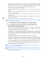
6.2. TEST AFTER THE CARRYING OUT OF INSTALLATION
6.2.1. TEST OF FUNCTIONALITY AND LEAKAGE TEST AFTER THE
END OF INSTALLATION
• For the test of functionality and leakage test use the gas for which the
terminal unit is intended or the medical air or nitrogen at the appropriate
pressure according to EN ISO 7396-1.
• Test the connectivity of counterparts of all installed terminal units, for
variants with the positioning of a counterpart of the quick connector
verify the right orientation of the quick connectors.
• Test the through-pass capacity of the terminal unit for presence of gas
on the outlet.
• Test the general tightness of the terminal unit and with all accessories
in the state with connected as well as disconnected counterparts of the
quick connectors. The leakage must not exceed 0.296 ml/min in any of
the described conditions (this corresponds to a change in the pressure
0.03 kPa.l/min for the leakage test for a pressure drop).
• Clean the terminal unit from possible impurities and check the integrity
and presence of all labels and markings.
Any other conditions of installation and procedures for testing after
installation are governed according to the applicable standard “EN ISO
7396-1”.
If any leakage or another defect of the terminal unit is discovered, use the
procedure described in Chapter 9.3 and return the unit for the carrying
out of the servicing activity.

9/60
EN
7. OPERATIONS
7.1. BEFORE USE
7.1.1. PREPARATION FOR USE OF THE TERMINAL UNIT
• Check if there is visible external damage to the terminal unit (including
the labels and marking). If it shows signs of external damages, avoid its
use and identify its status.
• Visually check if the product is contaminated; and if needed, use the
cleaning procedure detailed in this Manual in Chapter 8.
• Check the unit for leakage (e.g. by listening for leakage that can be
heard).
Terminal unit can be used only for the gas specifi ed on the button. Never
try to use it for di erent type of gas.
7.2. CONNECTION OF TERMINAL UNITS
7.2.1. LIST OF KNOWN ACCESSORIES
Hoses, fl ow rate meters, fans, underpressure reducing valves, suction
ejetors.
Any accessories used must be compatible with certain gas and with the
EN ISO 9170-1 standard.
Before connecting any accessories make sure that the patient is not
connected to the system.
7.2.2. CONNECTION OF MEDICAL DEVICES TO QUICK CONNEC
TORS
• Connect the medical device to the quick connector of the Terminal Unit.
• Check whether there is gas on the outlet of the medical device connected
(e.g. by setting the fl ow rate of the fl ow rate meter connected).
• Use the medical device connected in accordance with the manufacturer’s
instructions.
Never attempt to connect accessories designed for another type of gas
to the TU.
7.3. AFTER EVERY USE
Disconnect the medical devices used from the terminal unit.

10/60
EN
8. CLEANING
Remove general contamination with a soft cloth damped in oil free oxygen
compatible soap water and rinsed with clean water. Disinfection can be
carried out with an alcohol-based solution (spray or wipes).
If other cleaning solutions are used, check that they are not abrasive and
that they are compatible with brass, plastic materials of components, and
gas.
Do not use cleaning solutions containing ammonia!
Do not immerse in water or any liquid.
Do not expose to high temperature.
9. LIFETIME OF THE PRODUCT, MAINTENANCE
AND SERVICING
9.1. BATCH NUMBER AND PRODUCTION DATE
The number stamped on the terminal unit body consists of the following
data: GCE logo XXXXXXX
XXXXXXX: batch number
For example: The number 7366506 indicates a product with the batch
number 7366506.
9.1.1. PRODUCT LIFETIME AND WASTE MANAGEMENT
Housing - the maximum lifetime of this part of the product is given by the
lifetime of non-metallic materials used in the device and equals to the
lifetime of materials used in the pipeline distribution system.
Quick connection valve - the maximum lifetime is 10 years.
The owner of the equipment must avoid any repeated use of the product
(appropriate marking, degradation …).
Maintenance, servicing and repairs are described below.
At the end of the product’s life time (max. 10 years), the product must be
withdrawn from service. The owner of the device shall prevent the reuse
of the product and handle the product in compliance with “Directive of
European Parliament and Council 2008/98/EC on waste“.
In accordance to Article 33 of REACH GCE, s.r.o. as responsible
manufacturer shall inform all customers if materials containing 0.1% or
more of substances included in the list of Substance of Very High Concern
(SVHC).
The most commonly used brass alloys used for bodies and other brass
components contain 2-3% of lead (Pb), EC no. 231-468-6, CAS no. 7439-
92-1. The lead will not be released to the gas or surrounding environment
during normal use. After end of life the product shall be scrapped by an
authorized metal recycler to ensure e cient material handling with minimal
impact to environment and health.

11/60
EN
To date we have no information that indicates that other materials
containing SVHC of concentrations exceeding 0.1% are included in any
GCE product.
9.2. MAINTENANCE
GCE recommends the product owner to make regular visual inspections
at least once a year, including checks for tightness and right functioning of
the terminal unit (See Chapter 6.2).
If any leakage or defect is found, please use the procedure described in
Chapter 9.3, and ensure execution of the repair by a person authorised
by GCE.
Maximum usability time within the framework of the maintenance shall be
10 years.
Some repairs within the framework of the maintenance concerning
replacement of damaged or missing parts can be carried out by the
product owner. It is possible to replace the following parts only:
• labels
All labels on the product must be kept in a good and legible condition
during the entire product life time.
In order to identify a suitable component please contact our technical
assistance organisation. Users themselves cannot replace the parts with
a CE label without the consent of GCE.
The type of gas on the label must be the same as the gas stamped on the
body of the Terminal Unit.
9.3. SERVICING AND REPAIRS
Repair of TU can only be done by a person that owns appropriate
certifi cates according to national standards for mounting and repair of
medical devices, including EN ISO 7396-1 and EN ISO 5359 standards.
For more information and actual list of spare parts contact GCE or
distributor of GCE products.
Never dismantle or repair the product if connected to a pressure source.
All seals and O-rings must be kept in dry, dark and clean environment by
the provider and the user during the entire product life time.
Use only original GCE components!

12/60
EN
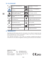
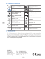
10. GLOSSARY
Consult instruction for
use
Suitable for Hospital
care use
Caution Suitable for Emergency
care use
Keep away from heat and
fl ammable material REF Catalogue number
Keep away from oil and
grease LOT Batch code
Humidity limit Fragile, handle with care
Temperature limit Use by date
Date of manufacture Manufacturer
A: Input parameter B: Output parameter
11. WARRANTY
The Standard Warranty period is two years from date of receipt by the
GCE Customer (or if this is not known 2 years from time of the product
manufacture shown on the product).
The standard warranty is only valid for products handled according to
Instruction for use (IFU) and general industry good practice and standards.
MANUFACTURER:
GCE, s.r.o. Tel : +420 569 661 111
Zizkova 381 Fax : +420 569 661 602
583 01 Chotebor http://www.gcegroup.com
Czech Republic © GCE, s.r.o.

13/60
SV
1. INLEDNING
Gasuttag från GCE är medicinska hjälpmedel klassifi cerade enl. direktivet
om medicintekniska produkter 93/42/EEG.
Överensstämmelsen med grundkraven i direktivet 93/42/EEG baseras på
norm EN ISO 9170-1.
2. AVSEDD ANVÄNDNING
Gasuttag är avsedda att användas i sjukhusets lågtrycks gasförsörjnings-
system. Till Gasuttagsenheten kan operatörer ansluta och koppla ett gas-
specifi kt inlopp till medicintekniska produkter, såsom medicinska slangar,
fl ödesmätare etc.
Gasuttaget är utformade för att vara gas specifi kt vilket innebär att de inte
kan anslutas till en medicinteknisk produkt som är av en annan typ av gas.
Gasuttagen skall inte tas i drift innan användaren har läst och förstått
dessa instruktioner.
Användaren av Gasuttagen måste vara väl utbildad för sådan drift - se
kapitel 4.
GRUNDLÄGGANDE VARIANTER AV GASUTTAG UPPDELNING EFTER
GAS:
• Andningsoxygen (O2)
• Andningsluft (AIR)
• Lustgas (nitrous oxide) (N2O)
• Blandgas
• Vacuum (VAC)
• Nitrogen (N2)
• Medicinsk koldioxid (CO2)
SVENSKA
BRUKSANVISNING: TU MINI

14/60
SV
3. SÄKERHETSKRAV VID DRIFT, TRANSPORT OCH
FÖRVARING
HÅLL PRODUKTEN, INKL. TILLBEHÖR, BORTOM PÅVERKAN FRÅN:
• Värmekällor (eld, cigaretter,..)
• Brännbara material,
• Olja eller fett, (var speciellt försiktig vid användnig av handkrämer)
• Vatten,
• Damm.
Produkten, inkl. tillbehör, måste vara skyddad mot vältning.
Följ alltid renlighetsföreskrifter för syrgas.
Använd endast produkten, inkl. tillbehör, i väl ventilerade utrymmen.
DRIFT FÖRUTSÄTTNINGAR LAGRING OCH TRANSPORT
-20/+60 °C -30/+70 °C
10/100% 20/70%
600/1200 mbar 600/1200 mbar
Före första användning skall produkten behållas i sitt originalemballage. I
det fall den tas ur drift (för transport, eller förvaring), rekommenderar GCE
att originalemballaget används (inkl. inre utfyllnadsmaterial).
Nationella lagar, kungörelser och föreskrifter för medicinska gaser, arbetar-
skydd och miljö skall följas.
DRIFTSÄKERHET
Gasuttag som beskrivs i detta dokument får endast användas för medicin-
ska gaser och säkerhetsföreskrifter för säker och tillförlitlig användning av
dessa medicinska komprimerade gaser måste följas i alla lägen.
4. INSTRUKTION AV PERSONAL
EU-direktivet 93/42/EEG om medicintekniska produkter föreskriver, att
den som levererar produkten, skall se till att all personal som hanterar
produkten, har tillgång till bruksanvisning och information om tekniska
data.
Använd inte produkten utan att ordentligt känna produkten och hur den
används på ett säkert sätt enligt Bruksanvisningen. Se till att användaren
har kännedom om specifi k information och kunskaper gällande den gas
som används.

15/60
SV
5. PRODUKTBESKRIVNING
101211798
13
654321
Gasuttagsenheter består av två huvuddelar:
• hus
• snabbkopplingsventil
Enskilda delar måste alltid utformas för samma typ av gas.
Vart och ett av dessa grundläggande delar är markerade med stämpling
som visar för vilken gas det är avsett.
En integrerad del av varje gasuttagsenhet är en backventil som släpper
igenom gasen när en motpart är ansluten men stänger automatiskt och
förhindrar gasen från att passera genom när motparten kopplas bort.
1) Hus
2) Tätning för service ventil
3) Serviceventil
4) O-ring
5) Låsnippel
6) Ventilhus
7) Etikett
8) Kåpa för utanpåliggande montage
9) Skruv
10) Dammplugg
11) Hylsa
12) Låsring
13) Kaross snabbkoppling
6. INSTALLATION
6.1. INSTALLATION
Installationen kan endast utföras av en person med lämpligt kunskap och
i enlighet med gällande föreskrifter och standard EN ISO 7396-1.
GCE rekommenderar användning av tillbehör utan något innehåll av fta-
later, i fråga om användning av tillbehör som innehåller ftalater bör du
överväga de risker som kan uppstå från dem för patienterna.

16/60
SV
VISUELL KONTROLL FÖRE INSTALLATION
• Kontrollera så att enheten (inklusive etiketter och märkning) inte är syn-
ligt skadade. Om det syns tecken på skada, driftsätt den inte. Anteckna
och markera dess skick.
• Gör en visuell kontroll om produkten inte är förorenad, om nödvändigt
fortsätt enligt rengöringsprocedurerna som är beskrivna i den här hand-
boken.
INSTALLATION
• Före montering, vänligen blås rent rörledningen invändigt.
• Kontrollera att tätningen (2) fi nns med innan installation av den samman-
satta backventilenenheter.
• Kontrollera om gasuttagsenhetens hölje är identisk med märkningen av
gasort på rörledningen.
• Använd ett silverlod (minst 40% av silver) för lödning, med låg
• smältpunkt (ca 600 ° C), kadmium-fri.
Vid montering använd alltid lämpliga och funktionella verktyg och följ
säkerhetskraven för drift, transport och lagring. Upprätthålla en lämplig
renhet av terminalenheten. (se Kapitel 3).
Det minsta centrum avståndet mellan 2 uttag måste vara minst 100 mm,
följande gasordning bör respekteras med början från vänster.
10 cm 10 cm 10 cm
1 2 3 4
O2 N2O Medical Air Medical aspirator
(vacuum)
6.1.1. INFÄLLT UTANPÅLIGGANDE MONTAGE GASUTTAG MINI
1 2 3 4 5 6 7 8 9 10 11 12 13 14

17/60
SV
1) Infästningsdosan
2) Ventilhus
3) Al-packning
4) Serviceventil
5) O-ring
6) Låsnippel
7) Ventilsatse
8) Gummibussningen
9) Namnring
10)Täckring
11) Plastkopp
12) Skruvarna
13) Tryckplatta
14) Fjäderring
FÖRUTSÄTTNING
• Infästningsdosan med ventilhus är redan noga uppriktad och
fastsatt i den färdiga väggen. Ventilhusets kopparrör är hårdlött till
kopplingsledningen för aktuell gas och lödskarven är tätprovad.
MONTERING
• Ta bort skyddslocket från infästningsdosan (1) med kniv eller skruvmejsel
och skruva ur blindproppen.
• Placera Al-packningen (3), lätt insmord med siliconfett, i ventilhuset (2).
• Kontrollera instämplad bokstav i serviceventilen (4): O=oxygen, A=luft,
N=lustgas.
• Montera rätt serviceventil i ventilhuset. Använd verktyg 202 200 514 och
dra fast med 12 Nm.
• Lägg O-ringen (5) i spåret på ventilsatsen (7) och skruva in kopplingen
i ventilhuset (2).
• Vrid ventilsatsen så att låsspåret i framkanten kommer ”klockan 12”. Lås
ventilsatsen i detta läge med låsnippeln (6). Använd 24 mm hylsnyckel
eller specialverktyg 202 200 513. Moment: 15 Nm.
• Tätprova anslutningen. Sätt gummibussningen (8) med fasningen vänd
utåt över kopplingen och pressa in den mot ventilhuset (2).
• Placera namnringen (9) i täckringen (10).
• Placera plastkoppen (11) i namnringen och trä den över gummibussningen.
Fäst plastkoppen i ventilhuset med de två spårskruvarna (12). Dra till så
att täckningen ligger tätt mot väggytan.
• Fixera tryckplattan (13) på ventilinsatsen med äderringen (14).
• Kontrollera de färdigmonterade gasuttagen genom att ansluta
snabbkopplingshandelar för respektive gassort.
• Kassera bipackade detaljer som är avsedda för utanpåliggande
montage.
Håll all utrustning, även händer, verktyg och arbetskläder, fria från fett
och olja.

18/60
SV
6.1.2. UTANPÅLIGGANDE MONTAGE GASUTTAG MINI
108 116 9
54321 712
1) Ventilhus
2) PA-packning
3) Serviceventil
4) O-ring
5) Låsnippel
6) Ventilsatse
7) Namnskylt
8) Omslag
9) Skruvarna
10) Dammplugg
11) Kopplingshylsan
12) Fjäderring
FÖRUTSÄTTNING
• Ventilhuset är fastskruvat på vägg ca 1,5 övergolv. Ventilhuset rör är
hårdlött till kopplingsröret och lödskarven tältprovad.
MONTERING
• Ta bort blindproppen fra ventilhuset (1). Placera PA-packningen (2) i
ventilhuset (1).
• Kontrollera instämplad bokstav i serviceventilen (3): O = Oxygen; N =
Luft; A = lustgas
• Montera rätt serviceventil i ventilhuset. Använd verktyg 202 200 514 och
dra fast med 12 Nm.
• Lägg O-ringen (4) i spåret på ventilsatsen (6) och skruva in kopplingen
i ventilhuset (1).
• Vrid ventilsatsen sa att låsspåret i framkanten kommer “klockan 12”. Lås
ventilsatsen i detta läge med låsnippeln (5). Använd 24mm hylsa eller
specialverktyg 202 200 513. Moment: 15 Nm.
• Testa anslutningen för läckor.
• Fäst dammpluggens (10) haka på locket med hjälp av öglan.
• Fäst namnskylten med de två skruvarna (9) och dra åt locket mot väggen.
• Placera hylsan (11) på ventilhuset och lås den med låsringen (12).
• Kontrollera de färdigmonterade gasutatagen genom atta nsluta
snabbkopplingshandelar för respektive gassort.
• Kassera bipackade detaljer som är avsedda för infällt montage.
Håll all utrustning, även händer, verktyg och arbetskläder, fri från fett och
olja.

19/60
SV
6.2. TEST EFTER UTFÖRD INSTALLATION
6.2.1. FUNKTIONS OCH LECKAGETEST EFTER SLUTFÖRD INSTAL
LATION
• För test av funktionalitet och täthetskontroll använd gasen för vilken ter-
minalen är avsedd för eller medicinsk luft eller kväve vid lämpligt tryck
enligt EN ISO 7396-1.
• Testa anslutning av motsvarande handelar till alla installerade terminal
enheter, för varianter med positionering av handelen till snabbkoppling-
en kontrollera att orienteringen är rätt.
• Testa genomlopps kapacitet i terminalenheten.
• Gör en allmän täthetskontroll av terminalenheten testa alla tillbehör
både med anslutna samt frånkopplade snabbkopplingar. Läckaget får
inte överstiga 0,296 ml / min i något av de beskrivna fallen (detta mot-
svarar en förändring i trycket med 0.03 kPa/min vid läckage).
• Rengör enheten från eventuella föroreningar och kontrollera integrite-
ten och närvaron av alla etiketter och märkningar.
Alla andra villkor för installation och förfaranden för testning efter instal-
lationen regleras enligt gällande standarden “EN ISO 7396-1 “.
Om något läckage eller någon annan defekt i terminalenheten upptäcks,
Följ proceduren som beskrivs i kapitel 9.3 och returnera enheten för ser-
vice.
7. OPERATIONER
7.1. FÖRE ANVÄNDNING
7.1.1. FÖRBEREDELSER FÖR ANVÄNDNING AV TERMINALEN
• Kontrollera om det fi nns några synliga skador på terminalen (inklusive
etiketter och märkning). Om det visar tecken på yttre skador, undvik
dess användning och gör en utredning om dess status.
• Visuellt kontrollera om produkten är förorenad, och om det behövs, följ
rengörings förfarandet som beskrivs i denna handbok i 8 kap.
• Kontrollera enheten för läckage (t.ex. genom att lyssna efter läckage
som kan vara hörbara).
Terminalenheten kan användas endast för den gas som anges på knap-
pen. Försök aldrig använda den för andra typer av gaser.

20/60
SV
7.2. ANSLUTNING TILL GASUTTAG
7.2.1. LISTA ÖVER KÄNDA TILLBEHÖR
Slangar, fl ödesmätare, fl äktar, undertrycksregulatorer, sugejektor.
Alla tillbehör som används måste vara kompatibel med gasen och med
EN ISO 9170-1 standarden.
Innan du ansluter några tillbehör se till att patienten inte är ansluten till
systemet.
7.2.2. ANSLUTNING AV MEDICINTEKNISKA PRODUKTER TILL
SNABBKOPPLINGAR
• Anslut den medicinska enheten till snabbkontakten på terminalenheten.
• Kontrollera om det fi nns gas i utloppet på den anslutna medicintekniska
enheten (t.ex. genom inställning av fl ödet för den anslutna fl ödesmä-
taren).
• Använd den medicinska enheten som är ansluten i enlighet med tillver-
karens instruktioner.
Försök aldrig att ansluta tillbehör avsedda för en annan typ av gas till
terminalenheten.
7.3. EFTER VARJE ANVÄNDNING
Koppla bort de medicintekniska produkter som inte används från termi-
nalen.
8. RENGÖRING
Avlägsna föroreningar med en mjuk trasa fuktad i oljefri, med syrgas kom-
patibel tvållösning och skölj med rent vatten.
Desinfektion kan utföras med alkoholbaserade lösningar (genom dusch-
ning eller avtorkning med trasa).
Om andra rengöringslösningar användes, se till att dessa lösningar inte
har abrasiv verkan och att de är kompatibla med mässing, komponenter
av plastmaterial, och gas.
Använd inte rengöringslösningar som innehåller ammoniak!
Utsätt inte utrustningen för inverkan från vatten eller andra vätskor.
Utsätt inte utrustningen för höga temperaturer.
A página está carregando...
A página está carregando...
A página está carregando...
A página está carregando...
A página está carregando...
A página está carregando...
A página está carregando...
A página está carregando...
A página está carregando...
A página está carregando...
A página está carregando...
A página está carregando...
A página está carregando...
A página está carregando...
A página está carregando...
A página está carregando...
A página está carregando...
A página está carregando...
A página está carregando...
A página está carregando...
A página está carregando...
A página está carregando...
A página está carregando...
A página está carregando...
A página está carregando...
A página está carregando...
A página está carregando...
A página está carregando...
A página está carregando...
A página está carregando...
A página está carregando...
A página está carregando...
A página está carregando...
A página está carregando...
A página está carregando...
A página está carregando...
A página está carregando...
A página está carregando...
A página está carregando...
A página está carregando...
-
 1
1
-
 2
2
-
 3
3
-
 4
4
-
 5
5
-
 6
6
-
 7
7
-
 8
8
-
 9
9
-
 10
10
-
 11
11
-
 12
12
-
 13
13
-
 14
14
-
 15
15
-
 16
16
-
 17
17
-
 18
18
-
 19
19
-
 20
20
-
 21
21
-
 22
22
-
 23
23
-
 24
24
-
 25
25
-
 26
26
-
 27
27
-
 28
28
-
 29
29
-
 30
30
-
 31
31
-
 32
32
-
 33
33
-
 34
34
-
 35
35
-
 36
36
-
 37
37
-
 38
38
-
 39
39
-
 40
40
-
 41
41
-
 42
42
-
 43
43
-
 44
44
-
 45
45
-
 46
46
-
 47
47
-
 48
48
-
 49
49
-
 50
50
-
 51
51
-
 52
52
-
 53
53
-
 54
54
-
 55
55
-
 56
56
-
 57
57
-
 58
58
-
 59
59
-
 60
60


GCE TERMINAL UNITS MINI Instruções de operação
- Tipo
- Instruções de operação
em outras línguas
Artigos relacionados
-
GCE MEDICONNECT Instruções de operação
-
-
-
-
-
-
-
-
-