
INSTRUCTIONS FOR USE
INSTRUÇÕES DE UTILIZAÇÃO
INSTRUCCIONES DE USO
NÁVOD K POUŽITÍ
HASZNÁLATI ÚTMUTATÓ
GCE HEALTHCARE
CS
HU
CENTRAL GAS SUPPLY SYSTEM
CENTRAL GASES SISTEMAS
SISTEMA CENTRAL DE SUMINISTRO DE GAS
CENTRÁLNÍ ROZVODOVÝ SYSTÉM PLYNU
KÖZPONTI GÁZELLÁTÓ RENDSZEREK
ES
PT
EN
MM90 HP UNIT
AUTO


3/64
EN
1. FOREWORD
These instructions for use cover essential information for the entire life cycle of the manifold:
• Installation,
• Operation and bank changeover,
• Alarm conditions,
• Maintenance and cleaning,
• Disposal.
GCE Medical central gas system is medical devices classified as class IIb according to the
Medical Device Directive 93/42/EEC.
Their Compliance with essential requirements of 93/42/EEC Medical Device Directive is based
upon EN ISO 7396-1 and EN 60601-1 standards.
2. INTENDED USE
The MM90 HP UNIT automatic medical manifold is intended for use in hospital pipeline system
as medical gas source. Together with MM90 HP UNIT shall always be used alarm providing all
alarms according to standard EN ISO7396-1 and as 2nd stage is recommended to use a line
pressure regulator.
This instruction for use details the operational and safety procedures for the MM90 HP UNIT
manifold. The MM90 HP UNIT manifold is available for Oxygen, Nitrous Oxide* and Compressed
Air, it can also be used for Carbon Dioxide*, Nitrogen, and gas blends for Medical Applications.
These manifolds are designed to operate at a maximum service pressure of 200 bar**.
Note: In Nitrous Oxide and Carbon Dioxide there is humidity due to the common production
methods, the mounting of a pre-heater per bank (total 2 pre-heaters per manifold) eliminates
possible working diculty of the manifold. These diculties are due to the fact that the gas,
when expanding, tends to produce ice.
Read this instruction before use of the product. Always follow this instruction!
The product shall only be used for the purpose described in this instruction!
The product must be installed by a qualified person and by compliance of all requirements of
ENISO 7396-1 as amended!
Before use, to guarantee the safety of the patient, check the equipment and the accessories
used with the product, so that data and performance comply with the intended use of the
product!
The product must not, under any circumstances be modified by other than the manufacturer!
The product must not be used for dierent gas than stated on the label.
These manifolds are designed to operate at a maximum service pressure of 50 bar!!!
** Maximum service pressure of 200 bar means for use with cylinders filled to a maximum
settled pressure of 200 bar (at 15 °C). At higher temperatures cylinder pressure will exceed
200 bar (developed pressure). For example developed pressure for oxygen at 50 °C is 240 bar.
The marking to be read on the regulator or manifold product label refer to max settled cylinder
pressure not developed cylinder pressure, this should match the pressure marking on the
cylinder.
ENGLISH
INSTRUCTION FOR USE: MM90 HP UNIT

4/64
EN
3. OPERATIONAL, TRANSPORT AND STORAGE SAFETY
REQUIREMENTS
KEEP THE PRODUCT AND ITS ASSOCIATED EQUIPMENT AWAY FROM:
• heat sources (fire, cigarettes,...)
• flammable materials,
• oil or grease (especially be careful if hand cream is used),
• water,
• dust.
The product and its associated equipment must be prevented from falling.
Always maintain oxygen cleanliness standards.
Use only the product and its associated equipment in a well ventilated area.
Before initial use the product shall be kept in its original packaging. GCE recommends use of
the original packaging (including internal sealing bag and caps) if the product is withdrawn from
operation (for transport and storage). Statutory laws, rules and regulations for medical gases,
accident prevention and environmental protection must be observed.
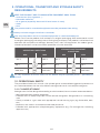
OPERATING CONDITIONS STORAGE AND TRANSPORT
CONDITIONS
MIN MAX MIN MAX
-20 °C +60 °C -30 °C +70 °C
20 % 70 % 20 % 70 %
600 mbar 1200 mbar 600 mbar 1200 mbar
It’s very important to assure access to this device only for qualified person – possibility of
misuse.
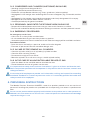
3.1. OPERATIONAL SAFETY
The panel described in this manual is for cylinder gases and the following general practices are
our recommendations for the safe, ecient storage and use of such compressed gases.
3.1.1. CYLINDER STORAGE
Storage area shall be designed according to valid standard, here are some recommendations:
• Well ventilated with weather protection.
• Free from fire risk. Keep away from sources of heat and ignition. Designated as a ‘no smoking’
area.
• Clearly marked as a gas store with appropriate hazard warning signs (e.g. flammable, toxic,
etc.).
• Kept clear with access restricted to authorised personnel.
• Provided with appropriate safety/emergency equipment (e.g. Fire extinguisher, breathing
apparatus etc.)

5/64
EN
3.1.2. COMPRESSED GAS CYLINDERS IN STORAGE SHOULD BE;
• Standing upright where designed for this.
• Properly secured to prevent overturning.
• Fitted with valve protection devices (e.g. Caps, guards etc.) where supplied.
• Segregated in the storage area according to the various categories (e.g. Flammable, oxidant
etc.).
• Segregated in the storage area according to content and clearly designated full or empty.
• Managed to ensure that the oldest stock is used first.
• Checked periodically for general condition.
3.1.3. PERSONNEL: WHO ENTER THE STORAGE AREA SHOULD BE;
• Responsible and competent to maintain the gas store and its contents as above.
• Familiar with and able to identify the contents of the gas containers and their potential hazards.
3.1.4. EMERGENCY PROCEDURES:
An emergency results from:
• A fire near or in the cylinder manifold room.
• An unintended leak of gas from the cylinders or pipeline.
• Some other potential or actual incident which will aect the integrity of the manifold installation.
Procedure to follow:
• Raise the alarm and notify a supervisor and/or call the fire brigade.
• Evacuate all personnel from the immediate danger area.
3.1.5. IN CASE OF FIRE, REMOVE ALL CYLINDERS:
• Close the cylinder valve(s) on all cylinder(s)/ cylinder bundles.
• Close the bank isolating valve(s).
• Disconnect the high pressure hoses.
• Move the cylinders to a safe area using a suitable cylinder trolley.
3.1.6. IN THE CASE OF AN UNCONTROLLABLE ESCAPE OF GAS:
• Open the doors to the manifold room to ventilate the area.
• Do not introduce sources of ignition into the area.
It is important that ready access to these instructions is given at all times and that the mani-
fold is not put into operation until the operator is fully familiar with its functions, controls and
safety precautions.
It is the duty of all employers to provide such information, training and supervision according
to national standards as is necessary to ensure so far as is reasonably practical the health and
safety at work of its employees.
4. PERSONNEL INSTRUCTIONS
The Medical Devices Directive 93/42/EEC states that product provider must ensure that all
personnel handling the product are provided with the operating instructions & performance
data.
Do not use the product without properly familiarization of the product and its safe operation as
defined in this Instruction for use. Ensure user is aware of particular information and knowledge
required for the gas in use.

6/64
EN
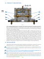
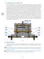
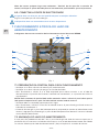
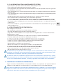
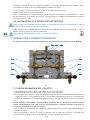
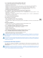
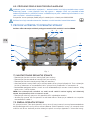
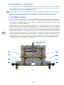
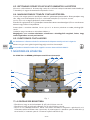
5. PRODUCT DESCRIPTION
Fig. 1
E
G
KCH
F
D
J
I
AB
The manifolds covered by these instructions are designed to allow equal numbers of cylinders
to be manifold together to give an operating bank and a reserve bank. The operating bank will
deliver gas to the manifold pressure regulator until the cylinders are exhausted. At that point the
supply will switch to the reserve bank and the exhausted bank can be replenished. The object
is to give uninterrupted gas supply.
The manifold consists of two manifold pressure regulators A&B, a shuttle valve C, two inlet shut
o valves D & E and two purge valves F & G. Pressure gauges I & J are fitted to the inlet side
downstream of D & E. They show the contents pressure of the two cylinder banks. An extra
gauge K, is also fitted to show the outlet pressure. Pressure switches are fitted to the inlet
downstream of D & E to indicate leaking reserve side and change of operating side. Pressure
switches are also fitted to the shuttle C to indicate high (“H” marking) and low (“L” marking)
outlet pressures. Two proximity switches are fitted to the shuttle C to indicate which bank is
in operation and it also decides which side is monitored for leaking reserve. The pressure
switches and the proximity switches shall be connected to an alarm panel to give a visual and
audible indication of the condition of the manifold. GCE recommend the use of gas alarm (see
chapter 12 - Accessories). The gas will exit the manifold through the outlet connection H.
6. INSTALLATION
* Manifold must be installed, the parameters should be set and tested in a room with a minimum
temperature of 10 °C. It is used according to the operating conditions listed in Chapter 3.
It is necessary that an installer of the product is trained and has an appropriate licence ac-
cording to national standards. It is outside the scope of these operating instructions to give
detailed guidance on installations.
The installation must conform to the standard MEDICAL GAS PIPELINE SYSTEMS EN ISO
7396-1 as amended. All tests according this standard have to be fulfilled.
When working with medical gases it is essential that no oil or grease come into contact with
the gas. This means that hands, tools and work clothes be free from oil or grease before any
work is undertaken. Components used for service must be gas compatible. For oxygen ser-
vice must also be degreased and although they will reach you in this condition care must be
taken during storage and handling.

7/64
EN
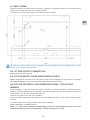
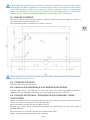
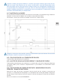
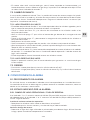
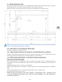
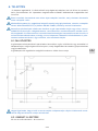
6.1. WALL FIXING
Positioning of the manifold consult with gas supplier and designer. Mount the manifold at the
height to suit either cylinders or cylinder bundles.
The holes to use for mounting the manifold are shown below.
Be aware that only upper screw is holding the entire weight of the manifold. Size of used
screws shall conform to total load.
6.2. FITTING OUTLET CONNECTION
Solder diameter 22 mm pipe.
6.3. FITTING SAFETY VALVE AND PURGE OUTLETS
Solder diameter 10 mm pipes. The pipes from safety valve and purge can (by use of a T-coupling)
be soldered together and have a common outlet outside the building.
6.4. FITTING TAILPIPES / HIGH PRESSURE HOSES / COLLECTING
BRANCH
Screw tailpipes / high pressure hoses from cylinders or cylinder bundles / collecting branch
onto the inlet connections on the manifold. Ensure that both the shut-o valve (D & E) and the
purge valves (F & G) are in the closed position.
Open one cylinder from one bank SLOWLY.
Check connection between tailpipe and inlet connection for leaks using a 0.5% teepol / water
solution.
If no leaks open remaining cylinders slowly from that bank.
Repeat operation on opposite bank.
Note: if a leak occurs between tailpipe/high pressure hose/collecting branch and inlet
connection check to see if sealing washer is fitted correctly or missing.

8/64
EN
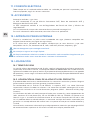
6.5. FITTING TO SOURCE OF ELECTRICITY
Any work with electric wiring must be carried out by a trained person with an appropriate
licence according to national standards.
Act upon instruction for use for gas alarm.
The product must be grounded through the anchor bolt at the protective earth label.
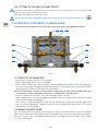
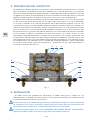
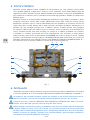
7. OPERATION AND BANK CHANGE OVER
The diagram below depicts the controls for normal operation of the MM 90 manifold.
Fig. 1
E
G
KCH
F
D
J
I
AB
7.1. START UP OF MANIFOLD
• Check both shut o valves D & E are closed.
• Check both purge valves F & G are closed.
• Open valve D slowly, left side will hereby become the operating side and start to supply gas
at a pressure of 9 bar through the outlet connection H. The cylinder pressure can be read on
the inlet gauge I and the outlet pressure on gauge K.
NOTE: Two proximity switches are fitted to the shuttle valve to electrically indicate which side
is in operation and it also decides which side is monitored for leaking reserve.
• Check all connection for leaks using a 0.5% teepol / water solution.
• Open valve E slowly. This will become the reserve side. The cylinder pressure of the reserve
bank can be read on inlet gauge J.
• The system is now supplying gas, with the left hand bank in operation and the right hand
bank on reserve. While gas is flowing, the pressure in the operating side will fall. This will be
indicated on the inlet gauge I.
7.2. BANK CHANGE OVER
At a pre-determined pressure of 7 bar the pressure from the reserve bank will push the piston
over in the shuttle valve and reserve bank will take over from the near empty bank of cylinders.
You will have an alarm “Change of operating side / Leakage on reserve side”. (see Chapter
8 – Alarm conditions).

9/64
EN
7.2.1. LEFT HAND LH SIDE EMPTIED
• The inlet pressure gauge I on the left-hand side is indicating exhausted cylinders, so the left-
hand bank of cylinders needs to be replaced.
• Close shut-o valve D and the isolating valves on the empty cylinders or cylinder bundles.
• Open purge valve F to vent any excess gas within the high pressure hose.
• Close purge valve F and disconnect high pressure hose from cylinders or cylinder bundles.
• Re-place empty cylinders with full ones.
• Re-connect high pressure hose to cylinders or cylinder bundles.
• Open cylinder valves slowly and leak test joints with 0.5% teepol in water solution.
• Open shut-o valve D and read the full content of the new cylinders on the inlet gauge I. The
alarm condition “Change of operating side / Leakage reserve side” will hereby be cancelled.
• The left hand side is now the reserve bank with full cylinders.
7.2.2.RIGHT HAND RH SIDE EMPTY
Repeat operation above for right hand bank to give an uninterrupted gas supply.
7.3. SHUT DOWN
• For short term (hours) shutdown close shut-o valves D & E.
• For long term (days) shutdown close shut-o valves D & E and the cylinder isolating valve.
8. ALARM CONDITIONS
8.1. ALARM PROCEDURE
On signal of alarm condition the appropriate visual indicator is illuminated on the gas alarm.
The alarm condition should be recorded and the necessary action taken, as detailed in the
sections below.
8.2. STATUS INDICATED BY ALARM
8.2.1. CHANGE OF OPERATING SIDE/ LEAKING RESERVE
If gauge I or J shows less than 140 bar (50 for N2O) you have alarm “Change of operating side”.
If gauge I or J shows more than 140 bar (50 for N2O) you have alarm “Leaking Reserve”.
Change of operating side actions:
• Replace the empty cylinders with full cylinders as described in chapter 7.
• Check that the audible and visual alarms on the gas alarm have been cancelled.
Leaking Reserve actions:
• Allocate the leakage using leak detecting spray. Isolate the leaking area and do repair/change
component or washer.
8.2.2. HIGH SUPPLY PRESSURE
• Check that the regulator outlet pressure is as preferred. If not, reset the regulator by turning
regulator screw.
• If you shortly after resetting the regulator have the same alarm condition again, the regulator
most likely has internal leakage. Replace the regulator with a new or refurbished unit.
8.2.3. LOW SUPPLY PRESSURE
• Check that the regulator outlet pressure is as preferred. If not, reset the regulator by turning
regulator screw.

10/64
EN
9. ROUTINE MAINTENANCE INSTRUCTION
Service shall be carried out only by authorised person according to national standards.
Use only original components. Contact GCE for further information about repair procedures.
The following routine checks should be made on a weekly basis:
• Check all valves for correct operation and leak test using a 0.5% teepol in water solution.
• Check pipework for leaks using a 0.5% teepol in water solution.
• Check that all notices are in place, can be easily read and are not obstructed from view.
• Inspect the vicinity of cylinders for anything introduced since last inspection, which could
aect the continuing safe operation of the manifold.
General maintenance should be undertaken in accordance with a planned maintenance
schedule, which should include the following items:
• Leak test all joints using a 0.5% teepol in water solution.
• Examine mounting frames and cylinder securing chains for damage deterioration and security
of attachment.
• Examine tailpipes/high pressure hoses for damage and security of attachment.
• High pressure hoses should receive particular attention to ensure they are secure, not worn
or otherwise weakened.
• Components with limited lifetimes, such as high pressure hoses, should be subjected to a
routine replacement programme.
• Filters are in good condition and not blocked. Filter elements may need to be cleaned or
renewed and pipelines may need to be blown through to remove foreign material.
• Valves to be used in normal or emergency operation are accessible and easy to operate.
Valves at service point’s outlets and purge valves should be checked for gas tightness.
• No item of equipment is overdue for any periodic inspection/test which may be applicable.
• The setting and operation of regulators is satisfactory.
• The necessary safety devices and instruments are fitted, are of the correct type and do not
show signs of deterioration or unauthorised interference.
• The equipment downstream of the outlet point is suitable for further service.
• Check connecting nuts and seating faces are undamaged.
• Check o-rings are undamaged.
• Check gauges operate smoothly and zero correctly.
• Check isolating valves for closure tightness and gland leakage.
• The gas manifold room must always remain thoroughly clean. Materials other than those
required for operating the manifold must not be stored in the room.
• Check that all ventilation grills are free from obstruction and that the extraction system (when
installed) is functioning correctly.
• Ensure that all restrictions on smoking and open fire are strictly enforced.
• Replace all worn or damaged parts with original spare parts. Remember that gaskets, o-rings
and sealing surfaces must be clean and free from damage to work eectively.
Safety note-as part of the planned maintenance special checks should be made to ensure:
All changes (including removal and addition of parts) and extensions conform to the right code
of practice.
Changes in the vicinity of the installation do not aect the safety of the operation e.g. proximity
of electricity to fuel gases, oils and combustibles near to oxygen, illicit use of a pipeline as an
electrical conductor or as a support for other items.

11/64
EN
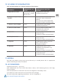
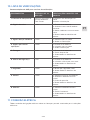
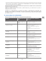
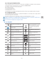
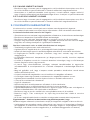
10. SCHEME OF EXAMINATION
GCE recommendations for a Written Scheme of Examination:
EQUIPMENT EXAMINATION IN
TERVAL
GUIDELINES OF WRITTEN
SCHEME
1. High pressure hoses Examine when chang-
ing cylinders, replace
every 5 years
a. Replace with new hose.
b. Record replacement.
2. Copper & Copper alloys
Tailpipes
1 year a. Visual, external examination.
b. Anneal if work-hardened or
replace.
c. Fit new seals where applicable.
d. Record all details of examination.
3. Stainless steel Tailpipes 5 years a. Replace with new tailpipe.
b. Record replacement.
4. Hoses for other duties 5 years a. Visual, external examination.
b. Replace with new hose.
c. Record replacement.
5. Pipe work 1 year a. Visual, external examination.
b. Pressure test.
c. Record all details of examination.
6. Safety Relief Valve 1 year a. Visual, external examination.
b. Pressure test.
c. Record all details of examination.
7. Regulator 5 years a. Replace with new or manufac-
turer’s refurbished unit.
b. Record all details.
8. Manifold 5 years a. Replace non-return valves.
b. Replace seals/glands/o-rings
c. Pressure test.
d. Record all details of examination.
9. Valves 5 years a. Replace seals/glands/o-rings.
b. Functional test.
c. Record all details of examination.
11. WIRING
Any work with electric wiring must be carried out by a trained person with an appropriate
licence according to national standards.
12. ACCESSORIES
Standard accessories – gas alarm.
GCE recommends the use of GCE Non Return Valves, GCE Collecting Branch, GCE High
Pressure Hoses.
GCE recommends the use of GCE Line Pressure Regulators and Safety valves.
Instruction for use for accessories are part of the final package.
For more information regarding accessories, see list in appendix 4.
Use only GCE original spare parts!

12/64
EN
13. CLEANING OF EXTERNAL PARTS
Remove dirt with a soft cloth damped in oil free oxygen compatible soap water and rinse with
clean water.
If other cleaning solutions are used, check that they are not abrasive and that they are
compatible with: Cu, Fe, Al alloy, brass, plastic materials of components, labels and gas.
Do not use cleaning solutions containing ammonia!
Do not immerse in water or any liquid.
Do not clean electrical connections when the power is on. Make sure the connections are dry
before turning power back on.
14. DISPOSAL
14.1. LIFE TIME
The maximum life time of the product is 10 years at compliance of Examination schedule
(chapter 10). At the end of the product’s life time, the product must be withdrawn from service.
The owner of the device shall prevent the reuse of the product and handle the product in
compliance with “Directive of European Parliament and Council 2008/98/EC on waste“.
14.2. DISPOSAL AT THE END OF THE PRODUCT’S LIFE TIME
Product must be recycled in compliance with the national and local regulations.
No part contains any chemical materials burdensome environment.
In accordance to Article 33 of REACH GCE, s.r.o. as responsible manufacturer shall inform all
customers if materials containing 0.1% or more of substances included in the list of Substance
of Very High Concern (SVHC).
The most commonly used brass alloys used for bodies and other brass components contain
2-3% of lead (Pb), EC no. 231-468-6, CAS no. 7439-92-1. The lead will not be released to the gas
or surrounding environment during normal use. After end of life the product shall be scrapped
by an authorized metal recycler to ensure ecient material handling with minimal impact to
environment and health.
To date we have no information that indicates that other materials containing SVHC of
concentrations exceeding 0.1% are included in any GCE product.
14.3. MANUFACTURING DATE
The manufacturing date is included in MM90 serial number which is marked on back plate.
Serial number composition is the following: YYMMXXXXXA
Y: 2 last numbers of the year of manufacture
M: month of manufacture
X: production number
A: made by GCE, s.r.o. CZ
The perforation in the device label indicates the year when the equipment has to be disposed
o.
14.4. REPAIR
Repair activities of GCE product must be carried out by GCE or authorized repair centers.
Contact GCE for further information about service available in your area.
All labels on the equipment must be kept in good, legible condition by the owner and the user
during the entire product life time.
Use only genuine GCE components.

13/64
EN
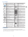
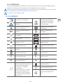
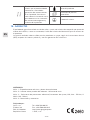
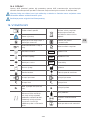
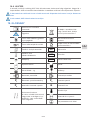
15. GLOSSARY
Consult instruction for use Take back equipment for
recycling. Do not dispose
equipment into unsorted
municipal waste
Caution!
Keep away from heat and
flammable materials Suitable for Hospital care use
Keep away from oil and
grease!
Take back battery for recy-
cling
Humidity limit SN Serial number
Temperature limit REF Catalogue number
Keep dry! LOT Batch code
Date of manufacture Manufacturer
Use by date Fragile, handle with care
Inlet parameter Outlet parameter
P1Inlet pressure range P2Outlet pressure
P4
Max outlet pressure (closing
pressure) QOutlet flow
Service or disposal date The
serial number indicates the
year product has to undergo
the overall maintenance ac-
tivities or has to be disposed
o. Refer to the serial number
note to determine the Overall
maintenance or disposal.
Weight of product
Atmospheric pressure limit
The protective earth label
16. WARRANTY
The Standard Warranty period is two years from date of receipt by the GCE Customer (or if this
is not known 2 years from time of the product manufacture shown on the product).
The standard warranty is only valid for products cu according to Instruction for use (IFU) and
general industry good practice and standards.

14/64
EN
APPENDIX:
Nr 1 – Technical specifications and performance data
Nr 2 – Testing report for relevant number of manifold – Serial Number
Nr 3 – Parameters of electric pressure switches, Setting pressure switches (1:O2, Air - 150 bar,
2: N2O, CO2 - 50bar)
Nr 4 – Spare parts and accessories
MANUFACTURER:
GCE, s.r.o. Tel: +420 569 661 111
Zizkova 381 Fax: +420 569 661 602
583 01 Chotebor http://www.gcegroup.com
Czech Republic © GCE, s.r.o.

15/64
PT
1. INTRODUÇÃO
Estas instruções cobrem todas as informações essenciais necessárias para a:
• Instalação,
• Funcionalidade e mudança de garrafa.
• Alarme,
• Manutenção e Limpeza,
• Eliminação
GCE Medical central gas system é um dispositivo medico de classe IIbde acordo com Medical
Device Directive 93/42/CEE.
Cumpre com os requisitos essenciais da directiva 93/42/CEE Medical Device Directive baseada
na EN ISO 7396-1 e na EN 60601-1 standards.
2. UTILIZAÇÃO PREVISTA
O uso da central MM90 HP UNIT está prevista para uma instalação de rede central de gases
medicinais em hospitais. Normalmente deve ser usado um alarme para fornecer todos os
alarmes necessários (tais como alarme). Como regulador de segundo estágio é recomendado
usar um regulador de linha ou de 2º estagio.
Estas instruções detalham os procedimentos operacionais e de segurança para a central
MM90 HP UNIT. A Central MM90 HP UNIT está disponível para O2, Ar e N2O, e também pode
ser utilizada para o CO2 *, N2, e misturas de gases para aplicações médicas. Estas centrias
estão projectadas para uma pressão de trabalho máxima de 200 bar **.
Nota: Com o N2O e o CO2 existe humidade devido à natureza dos gases liquefeitos, de modo
que uma instalação de aquecedores nos colectores (um total de 2 aquecedores por centrais)
irá remover possíveis dificuldades na operação da central. Essas dificuldades operacionais
podem surgir devido ao gelo que se forma quando o gás se expande.
Ler estas instruçoes antes de utilizar o dispositivo. Seguir sempre estas instruçoes!
O dispositivo so deve ser usado para os objectivos referidos nestas instruçoes!
O dispositivo deve ser instalado por pessoal qualificado e de acordo com todos os requisitos
da EN ISO 7396-1 !
Antes de usar, para garantia de segurança do paciente, verificar o equipamento e os aces-
sorios usados com o produto, por forma a que os dados e a performance estejam de acordo
com o seu objectivo!
O dispositivo nao deve ser, em nenhuma circunstancia, modificado sem ser pelo fabricante!
O dispositivo nao pode ser usado para outro gas diferente do que esta na etiqueta.
Estas centrias estão projectadas para uma pressão de trabalho máxima de 50 bar!!!
** A pressão máxima de 200 bar é para uso com garrafas cheias com uma pressão máxima de
200 bar (a 15 °C). A temperaturas mais altas a pressão do cilindro pode exceder os 200 bar
(pressão desenvolvida). Por exemplo, a pressão desenvolvida para O2 a 50 °C é de 240 bar.
A pressão indicada no regulador corresponde à pressão em garrafa a 15 °, que corresponde à
pressão marcada no cilindro.
PORTUGUÊS
INSTRUÇÕES DE USO: MM90 HP UNIT

16/64
PT
3. REQUÍSITOS DE FUNCIONAMENTO, TRANSPORTE E
SEGURANÇA DE ARMAZENAMENTO
MANTENHA A CENTRAL E AS SUAS INSTALAÇÕES ASSOCIADAS AFASTADAS DE:
• Fontes de calor (fogo, cigarros, …)
• Materiais inflamaveis,
• Oleo ou gordura,
• Agua,
• Pó.
Prevenir contra quedas as centrais e equipamentos associados.
Manter sempre os padrões de limpeza do O2.
Utilizar somente em áreas bem ventiladas.
Até à utilizaçao do dispositivo, manter o mesmo na sua embalagem original. A GCE recomenda
o uso da embalagem original (incluindo saco de proteçao e tampas) se o produto e retirado de
operaçao (para transporte ou armazenagem). Tenha em mente as leis, normas e regulamentos
nacionais para prevenção de acidentes e proteção do meio ambiente.
OPERATING CONDITIONS STORAGE AND TRANSPORT
CONDITIONS
MIN MAX MIN MAX
-20 °C +60 °C -30 °C +70 °C
20 % 70 % 20 % 70 %
600 mbar 1200 mbar 600 mbar 1200 mbar
É importante permitir apenas o acesso do pessoal qualificado a este manual – potencial mau
uso.
3.1. SEGURANÇA DE FUNCIONAMENTO
A central descrita neste manual é para um funcionamento com garrafas de gás e as seguintes
instruções são a nossa recomendação para uma utilização segura, um armazenamento
eficiente e um bom funcionamento com gases comprimidos.
3.1.1. ARMAZENAMENTO DE GARRAFAS
A área de armazenamento deve estar de acordo com as normas em vigor. Algumas
recomendações são:
• Área bem ventilada com proteção ambiental.
• Livre de risco de incêndio. Longe de fontes de calor ou ignição.
• Designadas como zonas de “Proibido fumar “.
• Área de armazenamento claramente marcada com sinais de alerta de gases (inflamáveis,
tóxicos, rádioactiva etc).
• Acesso limitado ao pessoal autorizado.
• Dotada de equipamentos adequados para a segurança / Extintores de emergência (incêndio,
respiração, etc.)

17/64
PT
3.1.2. CILINDROS DE GÁS COMPRIMIDO EM ARMAZENAMENTO DEVEM;
• Estar em posição vertical no seu lugar.
• Correctamente seguros para evitar quedas.
• Estar equipados com dispositivos de protecção para a válvula (bonés, tulipas, etc)..
• Separados na área de armazenamento por diferentes categorias (inflamáveis, Oxidantes etc)..
• Claramente separadas na área de armazenamento em função do conteúdo, indicando se
cheio / vazio.
• Organizado de forma a que as garrafas velhas sejam usados primeiro.
• O acompanhamento periódico das condições gerais.
3.1.3. FUNCIONÁRIOS: OPERADORES AUTORIZADOS A ENTRAR NA ÁREA DE
ARMAZENAMENTO DEVEM;
• Ser responsáveis e competentes para manter a área de armazenamento, conforme descrito
acima.
• Compreender e ser capaz de identificar o conteúdo das garrafas de gás e os seus riscos
potenciais.
3.1.4. PROCEDIMENTOS DE EMERGÊNCIA:
Uma emergência pode ser causado por:
• Incêndio perto da área de armazenamento da garrafa.
• Uma fuga de gás de forma não intencional.
• Quaisquer outros incidentes potenciais que podem afetar a instalação da central.
Procedimentos:
• Pressione o alarme e avisar o supervisor ou chame os bombeiros.
• Evacuar imediatamente o pessoal da área de risco.
3.1.5. REMOVER TODAS AS GARRAFAS EM CASO DE INCÊNDIO:
• Fechar as válvulas em todos os cilindros.
• Fechar a válvula de colector ou da alimentação geral.
• Desligar os flexíveis de alta pressão.
• Mover as garrafas para uma área segura com a ajuda dos carros porta- garrafa.
3.1.6. NO CASO DE UM FUGA INCONTROLÁVEL:
• Abrir as portas para ventilar a área.
• Não introduzir fontes de ignição na área.
É muito importante que estas instruções estejam sempre acessíveis e que a central nunca
seja posta em marcha por pessoal que não esteja totalmente familiarizado com as suas fun-
ções, controlos e precauções de segurança.
É o dever de todos os funcionários fornecer toda esta informação, formação e supervisão
segundo as normas nacionais, devido à necessidade de garantir a saúde e a segurança de
todos os funcionários.
4. INSTRUÇÕES DOS TRABALHADORES
De acordo com a Directiva 93/42/CEE de Dispositivos Médicos o fornecedor do produto deve
garantir que todos os funcionários que utilizam o produto dispõem das instruções de operação
e dos dados de desempenho.
Não use o produto sem estar devidamente familiarizado com o produto e a sua operação
segura, conforme descrito nestas Instruções de Utilização. Verifi que se o utilizador possui
informações e conhecimentos adequados necessários para o gás usado.

18/64
PT
5. DESCRIÇÃO DO PRODUTO
As centrais indicadas nestas instruções são projectadas para equipar um número suficiente de
cilindros para poder ter uma parte para abastecimento e outra de reserva, ao mesmo tempo. A
central vai fornecer gás a partir do lado operacional ao regulador de pressão até que a garrafa
se esgote. Nesse momento, o fornecimento de gás vai passar para o lado da reserva e o lado
esgotado pode ser substituido. O objectivo é manter um abastecimento ininterrupto de gás.
A central consiste de 2 reguladores de pressão A e B, válvula de inversão C, duas válvulas
de corte nas entradas D & E e duas válvulas de purga F & G. Manómetros de pressão I e J
estão montados na entrada D e E e marcam o conteúdo da pressão de ambos os lados das
entradas de garrafas. Outro manometro é montado sobre a válvula inversora C para indicar a
pressão de saída. Sensores de pressão estão montados sobre as entradas D e E para indicar
o lado de reserva. Há também sensores de pressão montados em contacto com a válvula
C para indicar a alta (marcado “H”) e a baixa (marcado como “L”) pressões de saída. Dois
contactos de proximidade estão montados sobre a válvula inversora C para indicar que lado é
que está a funcionar como backup. Os sensores de pressão e os contatos proximidade devem
ser conectados à caixa de alarme para dar um alarme visual e sonoro. Para o uso de alarmes
(ver Capítulo 12 - Acessórios).
Fig. 1
E
G
KCH
F
D
J
I
AB
6. INSTALAÇÃO
* A central deverá ser instalado, os parâmetros devem ser configurados e teste em uma sala
com temperatura mínima de 10 °C. É usado de acordo com as condições operacionais listadas
no Capítulo 3.
Não é o objectivo destas instruções de uso dar indicações detalhadas sobre como instalar
a central. É aconselhável que um instalador qualificado e reconhecido seja utilizado para
realizar a instalação.
É aconselhável que esta esteja de acordo com a norma EN ISO 7396-1 (sistemas e instalações
de gases medicinais). All tests according this standard have to be fulfilled.

19/64
PT
É extremamente importante que ao trabalhar com gases medicinais não exista nenhum con-
tacto do gás com óleos ou gorduras. Isso implica que as mãos, ferramentas e roupas devem
estar limpas de óleo ou gordura antes de iniciar qualquer operação. Todos os componentes
devem ser compatíveis com o gás. Para o O2 tem de vir desengorduradas, e mesmo assim
tem que tomar as devidas precauções durante a armazenagem e funcionamento.
6.1. FIXAÇÃO À PAREDE
Consulte o fabricante ou projectista para a colocação da central de gás. Montar a central à
altura desejada, conforme necessario.
Veja abaixo os orificios utilizados para montar a central.
Notar que apenas os parafusos do topo suportam todo o peso da central. Escolha os parafu-
sos do tamanho correcto a usar.
6.2. CONEXÃO DE SAIDA
Tubo de soldar de diámetro 22 mm.
6.3. VÁLVULA DE SEGURANÇA E AS SAÍDAS DAS PURGAS
Tubo de soldar 10 mm. Os tubos para a válvula de segurança e de purga podem (usando um
ligador tipo T) ser soldados juntos e ter a mesma saida para fora da instalação.
6.4. LIGAÇÃO DE PIGTAILS / FLEXÍVEÍS DE ALTA PRESSÃO / LIRAS /
COLECTORES
Aperte à entrada da central os flexíveis de alta pressão. Assegure-se que as válvulas de corte
(D & E) e as válvulas de purga (F & G) estão fechadas.
Abrir lentamente uma garrafa de um lado da central.
Verificar se há fugas entre a conexão de entrada e os flexíveis de alta pressão usando o
gazobul B140303.
Abra lentamente as restantes garrafas caso não existam fugas.
Repita a mesma operação do outro lado da central.

20/64
PT
Nota: Se houver qualquer fuga entre colectores / flexíveis de alta pressão e entradas da
central, verifique se ajunta de vedação está corretamente posicionada e que está presente.
6.5. CONECTAR A FONTE DE ELECTRICIDADE
A ligação deve ser feita por pessoal qualificado para instalações eléctricas.
Siga as instruções para o alarme de gás.
O dispositivo deve ser conectado a terra atraves do parafuso.
7. FUNCIONAMENTO E TROCA DO LADO DE
ABASTECIMENTO
O diagrama descreve os controlos do funcionamento normal da central MM90.
Fig. 1
E
G
KCH
F
D
J
I
AB
7.1. PREPARAÇÃO DA CENTRAL PARA O SEU FUNCIONAMENTO
• Verifique se as duas válvulas de corte D e E estão fechadas.
• Verifique se as duas válvulas de purga F e G estão fechadas.
• Abrir lentamente a válvula D, e o lado esquerdo passa desta maneira a ser o lado de
abastecimento. A pressão do cilindro é indicado no manómetro I, e a pressão de saída no
manómetro K.
NOTA: Dois contactos de proximidade estão montadas sobre a válvula C para indicar qual o
lado que está operacional e qual é o lado referido como o lado de reserva.
• Verifique todas as conexões contra possíveis fugas.
• Abrir lentamente a válvula E. Este será o lado de reserva. A pressão da garrafa de reserva é
indicada no manómetro J.
• A central fornece gás a partir do lado operacional (esquerdo) e mantem o lado direito como
reserva. Logo que haja fluxo de gás, a pressão do lado operacional descerá. Isto sera indicado
no manómetro de entrada I.
7.2. MUDANÇA DO LADO DO ABASTECIMENTO
A uma pressão predeterminada de 7 bar, a pressão do gás do lado da reserva empurrara o
pistão da válvula inversora e o lado de reserva passa a ser o lado de abastecimento. Será dado
um alarme “Mudança do lado de abastecimento.” (Veja o Capítulo 8 - estados de alarme.
A página está carregando...
A página está carregando...
A página está carregando...
A página está carregando...
A página está carregando...
A página está carregando...
A página está carregando...
A página está carregando...
A página está carregando...
A página está carregando...
A página está carregando...
A página está carregando...
A página está carregando...
A página está carregando...
A página está carregando...
A página está carregando...
A página está carregando...
A página está carregando...
A página está carregando...
A página está carregando...
A página está carregando...
A página está carregando...
A página está carregando...
A página está carregando...
A página está carregando...
A página está carregando...
A página está carregando...
A página está carregando...
A página está carregando...
A página está carregando...
A página está carregando...
A página está carregando...
A página está carregando...
A página está carregando...
A página está carregando...
A página está carregando...
A página está carregando...
A página está carregando...
A página está carregando...
A página está carregando...
A página está carregando...
A página está carregando...
A página está carregando...
A página está carregando...
-
 1
1
-
 2
2
-
 3
3
-
 4
4
-
 5
5
-
 6
6
-
 7
7
-
 8
8
-
 9
9
-
 10
10
-
 11
11
-
 12
12
-
 13
13
-
 14
14
-
 15
15
-
 16
16
-
 17
17
-
 18
18
-
 19
19
-
 20
20
-
 21
21
-
 22
22
-
 23
23
-
 24
24
-
 25
25
-
 26
26
-
 27
27
-
 28
28
-
 29
29
-
 30
30
-
 31
31
-
 32
32
-
 33
33
-
 34
34
-
 35
35
-
 36
36
-
 37
37
-
 38
38
-
 39
39
-
 40
40
-
 41
41
-
 42
42
-
 43
43
-
 44
44
-
 45
45
-
 46
46
-
 47
47
-
 48
48
-
 49
49
-
 50
50
-
 51
51
-
 52
52
-
 53
53
-
 54
54
-
 55
55
-
 56
56
-
 57
57
-
 58
58
-
 59
59
-
 60
60
-
 61
61
-
 62
62
-
 63
63
-
 64
64


em outras línguas
- español: GCE MM90 AUTO Instrucciones de operación
- slovenčina: GCE MM90 AUTO Návod na používanie
Artigos relacionados
-
GCE VARIMED Instruções de operação
-
-
-
-
-
-
-
-
-