Blackmagic 2110 IP Converter 3x3G Manual do usuário
- Tipo
- Manual do usuário

Blackmagic 2110 IP Converter 3x3G
October 2023
Installation and Operation Manual
Blackmagic
2110 IP
Converter 3x3G


Welcome
Thank you for purchasing your Blackmagic 2110 IP Converter 3x3G!
Your bidirectional IP converter lets you simultaneously convert SDI to IP and IP to SDI via
3 independent 3G-SDI inputs and outputs and a fast 10G Ethernet connection.
All 3G-SDI inputs feature loop outputs so you can install the converter in line within existing
SDI systems. Loop outputs plus converted outputs means you can feed up to 6 separate
HD channels to 6 separate SDI devices! The reference output is timed to the 2110 PTP
clock so you can sync all connected signals and the elegant front panel features control
buttons and a color LCD for monitoring, menus and diagnostics. You can even route IP
inputs from the panel!
This instruction manual should contain all the information you’ll need for installing your
Blackmagic 2110 IP Converter 3x3G and getting started.
Please check the support page on our web site at www.blackmagicdesign.com for the
latest version of the Blackmagic Converters software. When downloading software, please
register with your information so we can keep you updated when new software is released.
We are constantly working on new features and improvements, so we would love to
hear from you!
Grant Petty
CEO Blackmagic Design
English

Contents
Getting Started 5
Plugging in Power 5
Plugging in SDI Sources 5
Plugging in Ethernet 6
Subscribing to a Stream 6
Setting up a Network 7
Connecting to a Network Switch 7
PTP Grandmaster 8
NMOS Controller 8
Using The Front Panel 9
Home Screen 9
Using the LCD Menu 10
Settings 11
Outputs Menu 11
Audio Menu 12
Setup Menu 12
Rear Panel 15
Blackmagic Converters Setup 16
Inputs 16
Outputs 17
Setup 17
Blackmagic Universal Rack Shelf 20
Contents 20
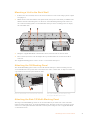
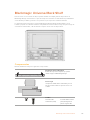
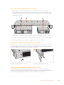
Mounting a Unit to the Rack Shelf 21
Attaching the 1/6 Blanking Panel 21
Attaching the Side 1/3 Width
Blanking Panel 21
Help 22
Regulatory Notices 23
Safety Information 24
Warranty 25
4Blackmagic 2110 IP Converter 3x3G

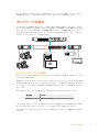
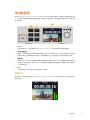
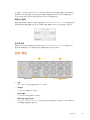
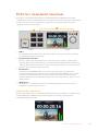
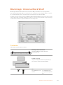
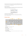
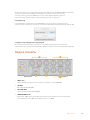
Getting Started
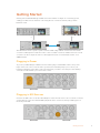
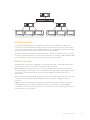
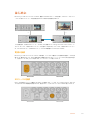
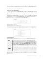
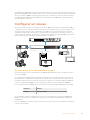
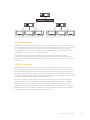
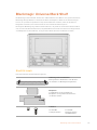
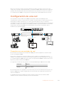
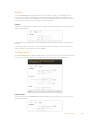
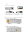
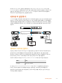
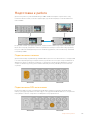
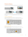
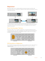
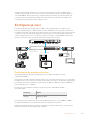
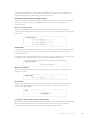
Getting started with Blackmagic 2110 IP Converter 3x3G is as simple as connecting power,
adding your SDI sources and then connecting the two converters directly using a Cat 6
Ethernet cable.
SDI SDI
Ethernet
INPUT DISP H/V
DELAY
3D
LUT 1
BLUE
ONLY ZOOM PEAK 3D
LUT 2
H
MARK
V
MARK
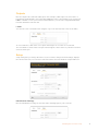
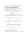
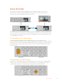
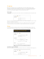
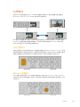
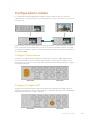
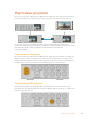
The illustration shows a point to point connection with a HyperDeck connected to the first IP
converter’s SDI input that sends the video to the second IP converter via Ethernet. The second
converter can then output the video to SDI equipment such as a SmartView monitor or an
ATEM switcher.
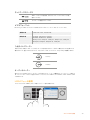
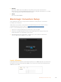
Plugging in Power
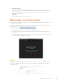
To power your Blackmagic 2110 IP Converter 3x3G, plug a standard IEC cable to the power
input on the rear of the converter. Once powered, the LCD will prompt you to select your
language. Using the menu dial, scroll to the language you wish to use and press the flashing
‘set’ button. This will take you to the home screen.
Plugging in SDI Sources
Connect the HD source to the first 3G-SDI input on the first unit. Your source could be a camera
or HyperDeck or any other 3G-SDI HD equipment. Once connected, the input will appear on
the front panel LCD.
5Getting Started

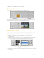
Using the second Blackmagic 2110 IP Converter 3x3G connect an SDI monitor or other SDI
equipment to the first SDI output on the rear of the unit.
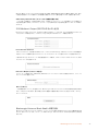
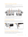
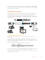
Plugging in Ethernet
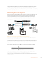
Now connect your two converters directly using a Cat 6 Ethernet cable.
The network status icon in the upper left corner of the LCD home screen will indicate ‘10G’
when a successful connection is made. This will be visible on both units.
SDI SDI
Ethernet
INPUT DISP H/V
DELAY
3D
LUT 1
BLUE
ONLY ZOOM PEAK 3D
LUT 2
H
MARK
V
MARK
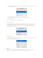
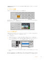
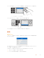
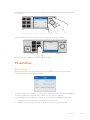
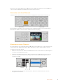
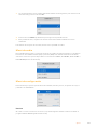
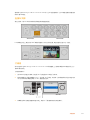
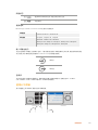
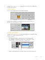
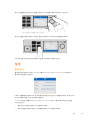
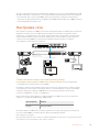
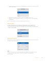
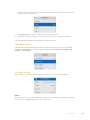
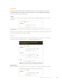
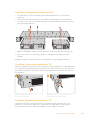
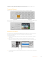
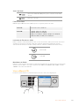
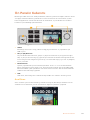
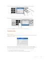
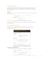
Subscribing to a Stream
On the front panel of the second Blackmagic 2110 IP Converter 3x3G you can now select the
stream for your SDI output using the menu. This is known as subscribing to a stream.
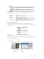
To subscribe to a stream:
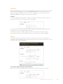
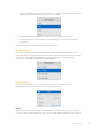
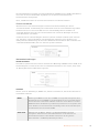
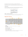
1 Press the ‘menu’ button to open the menu and press ‘set’ to select the ‘SDI
outputs’ submenu.
2 Rotate the menu dial to ‘SDI 1’ and press ‘set’. The streams from the first converter will
appear in a list which you can select by rotating the menu dial and pressing ‘set’.
LOCK
SET
MENU
3
2
11
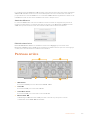
3 If the output doesn’t appear on the front panel display, press the ‘1’ button twice to change
to output mode.
6Getting Started

Your Blackmagic 2110 IP converters are now connected. You can also connect Blackmagic 2110
IP Converter 3x3G to a network with other IP video equipment including DeckLink IP and NMOS
controllers. Please keep reading the next section of this manual for information on how to
connect your Blackmagic 2110 IP Converter 3x3G to a 10G network switch to share multiple HD
video feeds over a network.
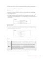
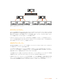
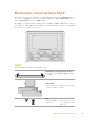
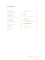
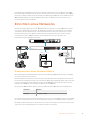
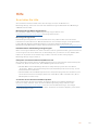
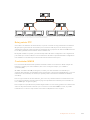
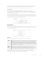
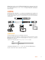
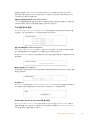
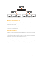
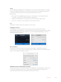
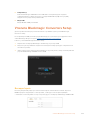
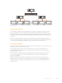
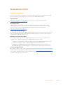
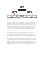
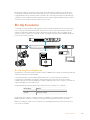
Setting up a Network
If this is your first time setting up a 10G network for streaming ST 2110 IP video, there are few
considerations you should take into account when getting started. IP media is sent in packets,
so it’s important to have a PTP aware switch to provide the timing information to synchronize
the devices connected to the network. The management of the traffic flow is covered by a
separate control system named NMOS that can be added to the network via either a software
or hardware solution.
SDI IN
SDI OUT
ETHERNET
+12V
+12V
SDI IN
SDI OUT
ETHERNET
+12V
+12V
STATUS ENTER
BACK
REF
TIME
BLACK
LTC
SDI
CMPST
EMBED SYSTEM ENABLE
AES PTP
INPUTS OUTPUTS
FRONT PANEL
USB
INT EXT TIME PWR1 PWR2 FAULT
SET
SEARCH
MENU
INPUT DISP H/V
DELAY
3D
LUT 1
BLUE
ONLY ZOOM PEAK 3D
LUT 2
H
MARK
V
MARK
1 213 314 415 516 617 819 920 1021 1122 1223
G25 G26
24718
SFP
SG200-26 26-Port Gigabit Smart Switch
System
Reset
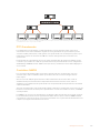
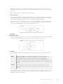
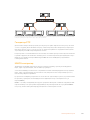
PTP Grandmaster
10G managed switch
NMOS Controller
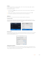
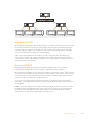
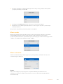
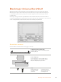
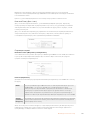
Connecting to a Network Switch
Your network switch needs to be a managed 10G network switch that supports IGMP version
3 snooping.
Managed switches provide monitoring and control of traffic over the network and require
configuration to get started. The size of you network switch depends on how much traffic you
might need. For instance, an 8 port 10G Ethernet switch has a capacity of 160Gbps and a 16
port switch will allow up to 320Gbps.
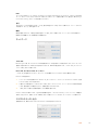
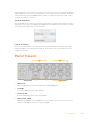
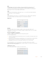
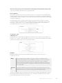
The following 10G network switches have been tested with Blackmagic 2110 IP Converter 3x3G:
Manufacturer Model
Ubiquiti Enterprise XG-24
The switch needs to be Internet Group Management Protocol, or IGMP L3 enabled. IGMP is a
communication protocol that allows the switch to route multicast data.
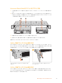
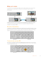
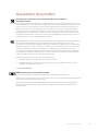
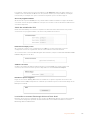
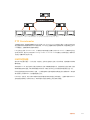
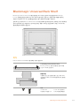
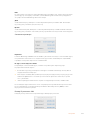
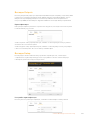
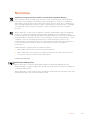
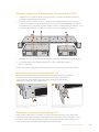
With multicasting one stream can be subscribed to by multiple outputs while only using the
bandwidth of one single stream.
7Setting up a Network

INPUT DISP H/V
DELAY
3D
LUT 1
BLUE
ONLY ZOOM PEAK 3D
LUT 2
H
MARK
V
MARK
INPUT DISP H/V
DELAY
3D
LUT 1
BLUE
ONLY ZOOM PEAK 3D
LUT 2
H
MARK
V
MARK INPUT DISP H/V
DELAY
3D
LUT 1
BLUE
ONLY ZOOM PEAK 3D
LUT 2
H
MARK
V
MARK INPUT DISP H/V
DELAY
3D
LUT 1
BLUE
ONLY ZOOM PEAK 3D
LUT 2
H
MARK
V
MARK
INPUT DISP H/V
DELAY
3D
LUT 1
BLUE
ONLY ZOOM PEAK 3D
LUT 2
H
MARK
V
MARK INPUT DISP H/V
DELAY
3D
LUT 1
BLUE
ONLY ZOOM PEAK 3D
LUT 2
H
MARK
V
MARK
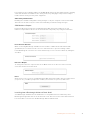
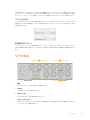
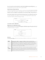
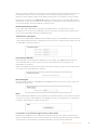
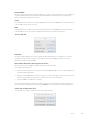
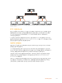
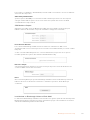
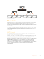
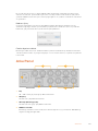
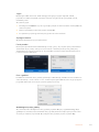
In the diagram above one ST 2110 stream has been subscribed to by 6 outputs but the bandwidth required by
the network switch bandwidth is for one stream only.
PTP Grandmaster
In order to maintain timing you need a Precision Time Protocol grandmaster or PTP clock
connected to the switch. Similar to using genlock via a master sync generator for synced SDI
connections, PTP generates accurate timing and frequency to maintain the packets of ST 2110
data over the network. This ensures that all streams are synchronized.
The PTP clock is the grandmaster and all other IP video devices should be set as the ‘follower’
to ensure no timing conflicts can occur. For more information on setting your Blackmagic 2110 IP
Converter 3x3G as a follower, refer to the ‘setup menu’ later in this manual.
NMOS Controller
Traditional SDI connections send signals in one direction with video, audio and ancillary data
such as timecode and closed captions embedded in the one signal.
With ST 2110, the signal is split into video, audio and ancillary data elementary streams. This
provides flexibility to route video, audio or ancillary data streams independently whilst keeping
each essence stream synchronized so they can be brought back together at the end of
the workflow.
This is all achieved through timing. But how does one converter know what the other converter
is doing? This is where the Networked Media Open Specifications, or NMOS for short, is
important.
NMOS is a group of specifications that direct the flow of traffic in an IP network and manage
communications between all the endpoint devices. Once a hardware or software NMOS
controller is connected to the network you can route any or all of the elementary streams to any
endpoint device on the network.
8Setting up a Network

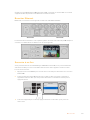
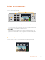
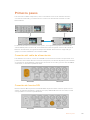
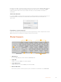
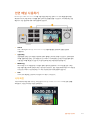
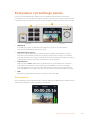
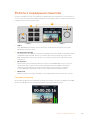
Using The Front Panel
When using Blackmagic 2110 IP Converter 3x3G any information you need to know is displayed
on the unit itself via the LCD home screen and the buttons and menu dial let you quickly
change settings. This section of the manual describes each feature on the front panel and what
it is used for.
LOCK
SET
MENU
3
2
1
1
2
3
4
1 USB-C
USB-C port for updates and configuring via Blackmagic Converters Setup utility.
2 Input and Output Buttons
The numbered buttons on the front panel let you select quickly between inputs and
outputs. To switch between input and output mode, double press any of the numbered
buttons. To see which mode you are in, check the icon on the home screen. The button will
illuminate when selected.
3 Menu Buttons
Use the menu and set buttons along with the menu dial to configure settings. The buttons
can also be locked by holding down the lock button until the button label illuminates red. To
unlock the buttons simply hold the lock button down again. More information on using the
LCD menu follows.
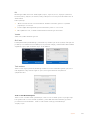
4 LCD
The LCD shows the home preview screen with status icons and LCD menu.
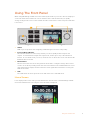
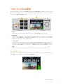
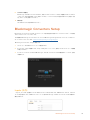
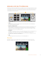
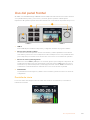
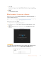
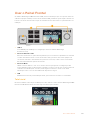
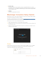
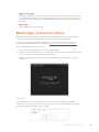
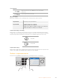
Home Screen
Icons displayed above the video preview indicate the current status of the Blackmagic 2110 IP
Converter 3x3G. Below is a description of the information displayed.
9Using The Front Panel

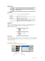
Network Status
Connected via 10G Ethernet point to point or via a network switch
Network not connected
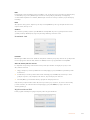
Video Standard
Blackmagic 2110 IP Converter 3x3G supports the following video standards:
SD Video 525i59.94 NTSC, 625i50 PAL
HD Video 720p50, 720p59.94, 720p60
1080i50, 1080i59.94, 1080i60
1080p23.98, 1080p24, 1080p25, 1080p29.97, 1080p30,
1080p50, 1080p59, 1080p59.94, 1080p60
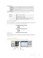
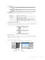
Input or Output Indicator
Displays the current input or output. Switch between input and output mode by double pressing
any of the numbered buttons. The numbered button will also illuminate when selected. Input
and output labels can be edited using the Converters Setup utility.
SDI input
SDI output
Audio Meters
Displays the audio levels of the selected input or output. Meter type can be selected via the
audio menu with options including VU -18dBFS, VU -20dBFS, PPM -18dBFS or PPM -20dBFS
reference levels.
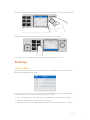
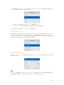
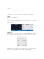
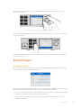
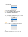
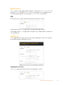
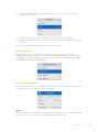
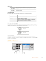
Using the LCD Menu
Press the ‘menu’ button on the front panel to open the menu settings.
LOCK
SET
MENU
3
2
1
10Using The Front Panel

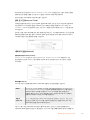
Turn the menu dial to navigate between the menu options and press ‘set’ to select a submenu.
LOCK
SET
MENU
3
2
1
Turn the menu dial to move through the menu settings
Using the menu dial, select the submenu option and press ‘set’ to confirm.
LOCK
SET
MENU
3
2
11
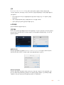
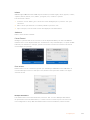
Press ‘menu’ to step back through the options and return to the home screen.
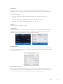
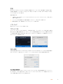
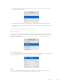
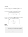
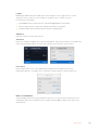
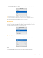
Settings
Outputs Menu
Use the output menu to route incoming ST 2110 sources to the SDI outputs on the rear of the
Blackmagic 2110 IP Converter 3x3G.
You can also route your sources and destinations using an NMOS controller. This will provide
flexibility to subscribe to the video, audio or ancillary essences.
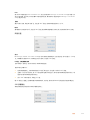
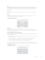
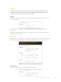
To route an ST 2110 stream to the SDI output on your Blackmagic 2110 IP Converter 3x3G:
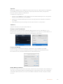
1 With the ‘outputs’ menu selected press the ‘set’ button.
2 Use the menu dial to select which SDI output you want to use and press the ‘set’ button.
11Settings

3 Available ST 2110 streams will appear in the list. Rotate the menu dial to select which stream
you want and press ‘set’.
4 Press the menu button repeatedly to return to the preview screen.
5 Now from the home screen make sure the same output is selected via the
numbered buttons.
To stop an incoming stream, select ‘none’ from the list.
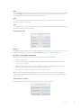
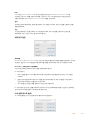
Audio Menu
The built in LCD shows audio meters for embedded audio channels. You can select to display
PPM or VU Meters. To change your meter type, expand the menu setting and select your
preferred audio meter display from the options from VU -18dBFS, VU -20dBFS, PPM -18dBFS or
PPM -20dBFS reference levels.
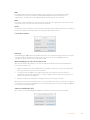
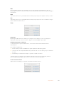
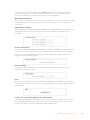
Setup Menu
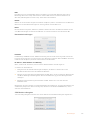
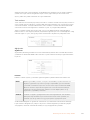
The setup menu contains settings including language selection, date and time options, network
settings and multicasting output settings.
Name
When more than one Blackmagic 2110 IP Converter 3x3G is on the network, you may wish to
give them discrete names. This can be done via Blackmagic Converters Setup.
12Settings

Language
Blackmagic 2110 IP Converter 3x3G supports 13 languages, including English, Chinese,
Japanese, Korean, Spanish, German, French, Russian, Italian, Portuguese, Turkish, Ukrainian
and Polish.
To select the language:
1 Press the ‘menu’ button and rotate the menu dial to the setup menu and press ‘set’
to select.
2 Rotate the menu dial to highlight your preferred language and press ‘set’.
3 Once selected, you will automatically return to the setup menu.
Software
Displays the current software version.
Front Panel
Set your Blackmagic converter’s front panel to ‘light’ mode for a brightly illuminated LCD. Use
‘dark’ mode for dimly lit environments where a bright LCD may be distracting, for example
multiple converter units mounted in a rack in a production facility.
Date and Time
Setting the date and time correctly ensures your Blackmagic 2110 IP Converter 3x3G has the
same time and date information as your network and also prevents conflicts that can occur with
some network systems.
Auto Set Date and Time
To set your date and time automatically select set the auto set date and time option to ‘on’..
When setting the date and time automatically, the converter will use the network time protocol
server set in the NTP field. To override the date and time manually, select ‘off’.
13Settings

NTP
The default NTP server is time.cloudflare.com, but you can also manually enter an alternate NTP
server using Blackmagic Converters Setup. For more information on setting the NTP server,
refer to Blackmagic Converters Setup later in this manual.
Date
To enter the date manually, select the date field and press set. Using the menu dial you can
select the day, month and year.
Time
To adjust the time, select time and press set. Use the menu dial to adjust the hours and minutes.
The internal clock is a 24 hour clock.
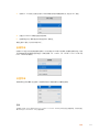
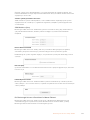
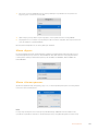
Network Settings
Protocol
Your Blackmagic 2110 IP Converter 3x3G is shipped set to static IP, so once connected, you can
assign an IP address. To change to DHCP, highlight the protocol option and press ‘set’.
IP Address, Subnet Mask and Gateway
When Static IP is selected you need to enter your network details manually.
To change the IP address
1 Rotate the menu dial to highlight ‘IP address’ and press the flashing ‘set’ button on your
converter’s front panel.
2 With a set of numbers underlined, press the ‘set’ button to highlight and rotate the menu
dial clockwise to increase or counter clockwise to decrease.
3 Press ‘set’ to confirm the change and move to the next value.
When you have finished entering your IP address, you can repeat these steps to adjust the
subnet mask and gateway. Once finished, press the flashing ‘menu’ button to exit and return to
the home screen.
2110 Multicast Output
Each streaming output is assigned a different multicast output address.
14Settings

This setting is similar to an IP address and lets other SMPTE 2110 IP equipment identify the
stream on your network. Each stream from your converter requires its own multicast output
address. NMOS controllers will also display the audio and ancillary data multicast addresses
associated with each source.
Reference Output
The dedicated reference out BNC connection on the rear lets you set the timing for other
devices connected to your Blackmagic 2110 IP Converter 3x3G. You can set your output
standard to SD or HD using the list selection.
Factory Reset
Highlight ‘factory reset’ in the setup menu to restore your Blackmagic 2110 IP Converter 3x3G to
factory settings. Once you press ‘set’, you will be prompted to confirm your selection.
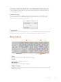
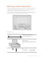
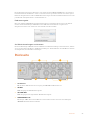
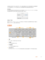
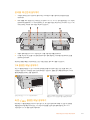
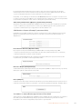
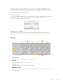
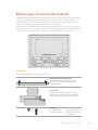
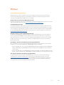
Rear Panel
1
4 5
2 3
6
1 Power
IEC C14 connector for 90 – 240 volt AC power supply.
2 SDI Out
3G-SDI video output BNC connectors.
3 SDI Loop Out
3G-SDI video loop output BNC connectors.
4 10G Ethernet PoE+
Blackmagic 2110 IP Converter 3x3G can be connected point to point or via a managed 10G
IGMP network switch.
15Rear Panel

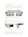
5 Ref Out
Your Blackmagic 2110 IP Converter 3x3G features a stabilized video reference output
corresponding to standard definition black burst and high definition tri-sync standards. For
more information on selecting your reference output, refer to the ‘settings’ section earlier in
this manual.
6 SDI In
3G-SDI video input BNC connectors.
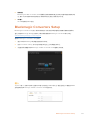
Blackmagic Converters Setup
Blackmagic Converters Setup is a software utility used to change settings and update the
internal software in your IP converter.
First, download and install the latest Blackmagic Converters software from the Blackmagic Design
support center at www.blackmagicdesign.com/support
To use Blackmagic Converters Setup:
1 Connect your Blackmagic converter to your computer via USB.
2 Launch Converters Setup. Your converter model will be named in the utility home page.
3 Click on the circular ‘setup’ icon or the image of your Blackmagic 2110 IP Converter 3x3G to
open the settings.
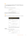
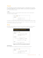
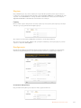
Inputs
Use the inputs tab to label the connected SDI inputs. The NMOS protocol broadcasts these
labels to make identifying them via an NMOS controller or other Blackmagic 2110 IP Converter
3x3G easy.
16Blackmagic Converters Setup

Outputs
Use the outputs tab to label the SDI outputs. For example, if SDI output 2 is connected to a
HyperDeck Studio HD Plus, enter ‘HyperDeck HD Plus’ in the output 2 field. If you are using an
NMOS controller to route your sources and destinations, you can select ‘HyperDeck HD Plus’
from the destination selection tab.
Labels
You can also save or load label sets using the cog icon in the lower left corner of the utility.
To save a label set, click on the save option and navigate to a location to save the file.
To load a label set, click on the load option and navigate to the location of your label set. Once
selected, click open.
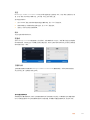
Setup
Setup settings let you change the name of your converter, change network settings, displays
the current version of your converter’s internal software and view multicast output addresses.
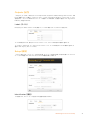
Identification Settings
Use the identification settings to enter the name and language for your converter.
17Blackmagic Converters Setup

Entering a custom name is helpful to identify the right Blackmagic 2110 IP Converter 3x3G when
more than one is connected to your network. It also provides the name for network location.
You can also identify the current software version.
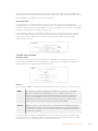
Date and Time
Set your date and time automatically by ticking the box. When setting the date and time
automatically, your converter will use the network time protocol server set in the NTP field. The
default NTP server is time.cloudflare.com, but you can also manually enter an alternate NTP
server and then click on ‘set’.
If you are entering your date and time manually, use the fields to enter your date, time and time
zone. Setting the date and time correctly ensures your recordings have the same time and
date information as your network and also prevents conflicts that can occur with some network
storage systems.
Network Settings
Network Location
The network location is the name for your Blackmagic 2110 IP Converter 3x3G that will appear
in the registry. This is based on the identification name at the top of the setup utility. It’s worth
noting that numeric prefixes will be ignored.
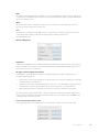
Protocol
DHCP and static IP settings let you determine how your converter is connected to your network.
DHCP Blackmagic 2110 IP converters are set to DHCP by default. The dynamic host
configuration protocol, or DHCP, is a service on network servers that automatically
finds your converter and assigns an IP address. DHCP is a great service that makes
it easy to connect equipment via Ethernet and ensure their IP addresses do not
conflict with each other. Most computers and network switchers support DHCP.
Static IP When ‘static IP’ is selected, you can enter your network details manually. When
setting IP addresses manually so all units can communicate, they must share the
same subnet mask and gateway settings.
When using static IP and there are other devices on the network that have the same identifying
number in their IP address there will be a conflict and the units won’t connect. If you encounter
a conflict, simply change the identifying number in the unit’s IP address.
18Blackmagic Converters Setup

For example, if the conflicting address is 192.100.40.30 change the last number field to anything
other than 30. If the new number is also being used, keep changing it until you find a unique
number that isn’t being used by other equipment.
Allow utility administration
Enabling the ‘via USB’ setting limits setting changes to only the computer connected via USB.
This removes the risk of anyone on the network making accidental settings changes.
2110 Multicast Output
Each ST 2110 stream output from your Blackmagic 2110 IP Converter 3x3G uses its own
multicast output address. These can be found via the setup utility or by using the LCD menu.
Precision Time Protocol
When connecting Blackmagic 2110 IP Converter 3x3G to a 10G network switch with a PTP
grandmaster, the converter needs to be set to follower mode to prevent a timing conflict.
If two Blackmagic IP converters are connected directly, set one to be the follower by ticking the
checkbox.
Reference Output
To change the reference output for the ref out BNC connector on the rear of the converter,
select the reference from the menu.
Reset
Click ‘factory reset’ to restore your Blackmagic 2110 IP Converter 3x3G to factory settings. Once
you press ‘set’, you will be prompted to confirm your selection. To proceed, click ‘reset’.
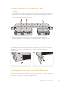
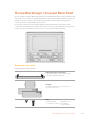
Installing into a Blackmagic Universal Rack Shelf
Your Blackmagic 2110 IP Converter 3x3G shares a compatible form factor with many other
Blackmagic Design units that can be mounted in a rack. The next section of this manual shows
how to install the converter into the Blackmagic Universal Rack Shelf.
19Blackmagic Converters Setup

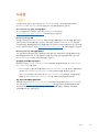
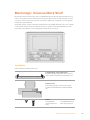
Blackmagic Universal Rack Shelf
Blackmagic Universal Rack Shelf is a 1RU shelf that lets you install a broad range of
Blackmagic Design equipment into a broadcast rack or road case. The modular design means
you can build portable and practical equipment setups using products that share a single rack
unit form factor.
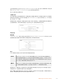
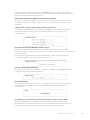
The illustration below shows 3 Universal Rack Shelves installed in a small rack with a
combination of compatible units mounted. The bottom shelf includes a 1/3 rack width blanking
panel to fill unused space between units.
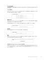
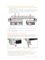
Contents
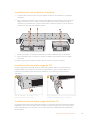
The Universal Rack Shelf Kit contains the following items.
1 x Blackmagic Universal Rack Shelf
A single rack unit, full width shelf for installing
Blackmagic Design equipment.
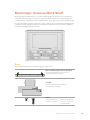
Blanking Panels
1 x 1/6 rack width and 2 x 1/3 rack width blanking
panels to cover unused shelf space.
Screws
12 x M3 5mm
countersunk mounting
screws.
2 x M3 9mm flat screws
for 1/6 blanking panels.
20Blackmagic Universal Rack Shelf
A página está carregando...
A página está carregando...
A página está carregando...
A página está carregando...
A página está carregando...
A página está carregando...
A página está carregando...
A página está carregando...
A página está carregando...
A página está carregando...
A página está carregando...
A página está carregando...
A página está carregando...
A página está carregando...
A página está carregando...
A página está carregando...
A página está carregando...
A página está carregando...
A página está carregando...
A página está carregando...
A página está carregando...
A página está carregando...
A página está carregando...
A página está carregando...
A página está carregando...
A página está carregando...
A página está carregando...
A página está carregando...
A página está carregando...
A página está carregando...
A página está carregando...
A página está carregando...
A página está carregando...
A página está carregando...
A página está carregando...
A página está carregando...
A página está carregando...
A página está carregando...
A página está carregando...
A página está carregando...
A página está carregando...
A página está carregando...
A página está carregando...
A página está carregando...
A página está carregando...
A página está carregando...
A página está carregando...
A página está carregando...
A página está carregando...
A página está carregando...
A página está carregando...
A página está carregando...
A página está carregando...
A página está carregando...
A página está carregando...
A página está carregando...
A página está carregando...
A página está carregando...
A página está carregando...
A página está carregando...
A página está carregando...
A página está carregando...
A página está carregando...
A página está carregando...
A página está carregando...
A página está carregando...
A página está carregando...
A página está carregando...
A página está carregando...
A página está carregando...
A página está carregando...
A página está carregando...
A página está carregando...
A página está carregando...
A página está carregando...
A página está carregando...
A página está carregando...
A página está carregando...
A página está carregando...
A página está carregando...
A página está carregando...
A página está carregando...
A página está carregando...
A página está carregando...
A página está carregando...
A página está carregando...
A página está carregando...
A página está carregando...
A página está carregando...
A página está carregando...
A página está carregando...
A página está carregando...
A página está carregando...
A página está carregando...
A página está carregando...
A página está carregando...
A página está carregando...
A página está carregando...
A página está carregando...
A página está carregando...
A página está carregando...
A página está carregando...
A página está carregando...
A página está carregando...
A página está carregando...
A página está carregando...
A página está carregando...
A página está carregando...
A página está carregando...
A página está carregando...
A página está carregando...
A página está carregando...
A página está carregando...
A página está carregando...
A página está carregando...
A página está carregando...
A página está carregando...
A página está carregando...
A página está carregando...
A página está carregando...
A página está carregando...
A página está carregando...
A página está carregando...
A página está carregando...
A página está carregando...
A página está carregando...
A página está carregando...
A página está carregando...
A página está carregando...
A página está carregando...
A página está carregando...
A página está carregando...
A página está carregando...
A página está carregando...
A página está carregando...
A página está carregando...
A página está carregando...
A página está carregando...
A página está carregando...
A página está carregando...
A página está carregando...
A página está carregando...
A página está carregando...
A página está carregando...
A página está carregando...
A página está carregando...
A página está carregando...
A página está carregando...
A página está carregando...
A página está carregando...
A página está carregando...
A página está carregando...
A página está carregando...
A página está carregando...
A página está carregando...
A página está carregando...
A página está carregando...
A página está carregando...
A página está carregando...
A página está carregando...
A página está carregando...
A página está carregando...
A página está carregando...
A página está carregando...
A página está carregando...
A página está carregando...
A página está carregando...
A página está carregando...
A página está carregando...
A página está carregando...
A página está carregando...
A página está carregando...
A página está carregando...
A página está carregando...
A página está carregando...
A página está carregando...
A página está carregando...
A página está carregando...
A página está carregando...
A página está carregando...
A página está carregando...
A página está carregando...
A página está carregando...
A página está carregando...
A página está carregando...
A página está carregando...
A página está carregando...
A página está carregando...
A página está carregando...
A página está carregando...
A página está carregando...
A página está carregando...
A página está carregando...
A página está carregando...
A página está carregando...
A página está carregando...
A página está carregando...
A página está carregando...
A página está carregando...
A página está carregando...
A página está carregando...
A página está carregando...
A página está carregando...
A página está carregando...
A página está carregando...
A página está carregando...
A página está carregando...
A página está carregando...
A página está carregando...
A página está carregando...
A página está carregando...
A página está carregando...
A página está carregando...
A página está carregando...
A página está carregando...
A página está carregando...
A página está carregando...
A página está carregando...
A página está carregando...
A página está carregando...
A página está carregando...
A página está carregando...
A página está carregando...
A página está carregando...
A página está carregando...
A página está carregando...
A página está carregando...
A página está carregando...
A página está carregando...
A página está carregando...
A página está carregando...
A página está carregando...
A página está carregando...
A página está carregando...
A página está carregando...
A página está carregando...
A página está carregando...
A página está carregando...
A página está carregando...
A página está carregando...
A página está carregando...
A página está carregando...
A página está carregando...
A página está carregando...
A página está carregando...
A página está carregando...
A página está carregando...
A página está carregando...
A página está carregando...
A página está carregando...
A página está carregando...
A página está carregando...
A página está carregando...
A página está carregando...
A página está carregando...
A página está carregando...
A página está carregando...
A página está carregando...
A página está carregando...
A página está carregando...
A página está carregando...
A página está carregando...
A página está carregando...
A página está carregando...
A página está carregando...
A página está carregando...
A página está carregando...
A página está carregando...
A página está carregando...
A página está carregando...
A página está carregando...
A página está carregando...
A página está carregando...
A página está carregando...
A página está carregando...
A página está carregando...
A página está carregando...
A página está carregando...
A página está carregando...
A página está carregando...
A página está carregando...
A página está carregando...
A página está carregando...
A página está carregando...
A página está carregando...
A página está carregando...
A página está carregando...
A página está carregando...
A página está carregando...
A página está carregando...
A página está carregando...
A página está carregando...
A página está carregando...
-
 1
1
-
 2
2
-
 3
3
-
 4
4
-
 5
5
-
 6
6
-
 7
7
-
 8
8
-
 9
9
-
 10
10
-
 11
11
-
 12
12
-
 13
13
-
 14
14
-
 15
15
-
 16
16
-
 17
17
-
 18
18
-
 19
19
-
 20
20
-
 21
21
-
 22
22
-
 23
23
-
 24
24
-
 25
25
-
 26
26
-
 27
27
-
 28
28
-
 29
29
-
 30
30
-
 31
31
-
 32
32
-
 33
33
-
 34
34
-
 35
35
-
 36
36
-
 37
37
-
 38
38
-
 39
39
-
 40
40
-
 41
41
-
 42
42
-
 43
43
-
 44
44
-
 45
45
-
 46
46
-
 47
47
-
 48
48
-
 49
49
-
 50
50
-
 51
51
-
 52
52
-
 53
53
-
 54
54
-
 55
55
-
 56
56
-
 57
57
-
 58
58
-
 59
59
-
 60
60
-
 61
61
-
 62
62
-
 63
63
-
 64
64
-
 65
65
-
 66
66
-
 67
67
-
 68
68
-
 69
69
-
 70
70
-
 71
71
-
 72
72
-
 73
73
-
 74
74
-
 75
75
-
 76
76
-
 77
77
-
 78
78
-
 79
79
-
 80
80
-
 81
81
-
 82
82
-
 83
83
-
 84
84
-
 85
85
-
 86
86
-
 87
87
-
 88
88
-
 89
89
-
 90
90
-
 91
91
-
 92
92
-
 93
93
-
 94
94
-
 95
95
-
 96
96
-
 97
97
-
 98
98
-
 99
99
-
 100
100
-
 101
101
-
 102
102
-
 103
103
-
 104
104
-
 105
105
-
 106
106
-
 107
107
-
 108
108
-
 109
109
-
 110
110
-
 111
111
-
 112
112
-
 113
113
-
 114
114
-
 115
115
-
 116
116
-
 117
117
-
 118
118
-
 119
119
-
 120
120
-
 121
121
-
 122
122
-
 123
123
-
 124
124
-
 125
125
-
 126
126
-
 127
127
-
 128
128
-
 129
129
-
 130
130
-
 131
131
-
 132
132
-
 133
133
-
 134
134
-
 135
135
-
 136
136
-
 137
137
-
 138
138
-
 139
139
-
 140
140
-
 141
141
-
 142
142
-
 143
143
-
 144
144
-
 145
145
-
 146
146
-
 147
147
-
 148
148
-
 149
149
-
 150
150
-
 151
151
-
 152
152
-
 153
153
-
 154
154
-
 155
155
-
 156
156
-
 157
157
-
 158
158
-
 159
159
-
 160
160
-
 161
161
-
 162
162
-
 163
163
-
 164
164
-
 165
165
-
 166
166
-
 167
167
-
 168
168
-
 169
169
-
 170
170
-
 171
171
-
 172
172
-
 173
173
-
 174
174
-
 175
175
-
 176
176
-
 177
177
-
 178
178
-
 179
179
-
 180
180
-
 181
181
-
 182
182
-
 183
183
-
 184
184
-
 185
185
-
 186
186
-
 187
187
-
 188
188
-
 189
189
-
 190
190
-
 191
191
-
 192
192
-
 193
193
-
 194
194
-
 195
195
-
 196
196
-
 197
197
-
 198
198
-
 199
199
-
 200
200
-
 201
201
-
 202
202
-
 203
203
-
 204
204
-
 205
205
-
 206
206
-
 207
207
-
 208
208
-
 209
209
-
 210
210
-
 211
211
-
 212
212
-
 213
213
-
 214
214
-
 215
215
-
 216
216
-
 217
217
-
 218
218
-
 219
219
-
 220
220
-
 221
221
-
 222
222
-
 223
223
-
 224
224
-
 225
225
-
 226
226
-
 227
227
-
 228
228
-
 229
229
-
 230
230
-
 231
231
-
 232
232
-
 233
233
-
 234
234
-
 235
235
-
 236
236
-
 237
237
-
 238
238
-
 239
239
-
 240
240
-
 241
241
-
 242
242
-
 243
243
-
 244
244
-
 245
245
-
 246
246
-
 247
247
-
 248
248
-
 249
249
-
 250
250
-
 251
251
-
 252
252
-
 253
253
-
 254
254
-
 255
255
-
 256
256
-
 257
257
-
 258
258
-
 259
259
-
 260
260
-
 261
261
-
 262
262
-
 263
263
-
 264
264
-
 265
265
-
 266
266
-
 267
267
-
 268
268
-
 269
269
-
 270
270
-
 271
271
-
 272
272
-
 273
273
-
 274
274
-
 275
275
-
 276
276
-
 277
277
-
 278
278
-
 279
279
-
 280
280
-
 281
281
-
 282
282
-
 283
283
-
 284
284
-
 285
285
-
 286
286
-
 287
287
-
 288
288
-
 289
289
-
 290
290
-
 291
291
-
 292
292
-
 293
293
-
 294
294
-
 295
295
-
 296
296
-
 297
297
-
 298
298
-
 299
299
-
 300
300
-
 301
301
-
 302
302
-
 303
303
-
 304
304
-
 305
305
-
 306
306
-
 307
307
-
 308
308
-
 309
309
-
 310
310
-
 311
311
-
 312
312
-
 313
313


Blackmagic 2110 IP Converter 3x3G Manual do usuário
- Tipo
- Manual do usuário
em outras línguas
Artigos relacionados
-
Blackmagic Desktop Video Manual do usuário
-
Blackmagic Teranex Mini Manual do usuário
-
-
-
-
Blackmagic MC HDMI-SDI wPSU Manual do usuário
-
-
-