Yamaha MagicStomp Manual do proprietário
- Categoria
- Programas
- Tipo
- Manual do proprietário
Este manual também é adequado para

GUITAR EFFECTS PROCESSOR

2
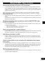
1. IMPORTANT NOTICE: DO NOT MODIFY THIS
UNIT!
This product, when installed as indicated in the
instructions contained in this manual, meets
FCC requirements. Modifications not expressly
approved by Yamaha may void your authority,
granted by the FCC, to use the product.
2. IMPORTANT: When connecting this product to
accessories and/or another product use only
high quality shielded cables. Cable/s supplied
with this product MUST be used. Follow all
installation instructions. Failure to follow in-
structions could void your FCC authorization to
use this product in the USA.
3. NOTE: This product has been tested and found
to comply with the requirements listed in FCC
Regulations, Part 15 for Class “B” digital de-
vices. Compliance with these requirements
provides a reasonable level of assurance that
your use of this product in a residential environ-
ment will not result in harmful interference with
other electronic devices. This equipment gener-
ates/uses radio frequencies and, if not installed
and used according to the instructions found in
the users manual, may cause interference
harmful to the operation of other electronic
devices. Compliance with FCC regulations does
not guarantee that interference will not occur in
all installations. If this product is found to be the
source of interference, which can be determined
by turning the unit “OFF” and “ON”, please try to
eliminate the problem by using one of the
following measures:
Relocate either this product or the device that is
being affected by the interference.
Utilize power outlets that are on different branch
(circuit breaker or fuse) circuits or install AC
line filter/s.
In the case of radio or TV interference, relocate/
reorient the antenna. If the antenna lead-in is
300 ohm ribbon lead, change the lead-in to co-
axial type cable.
If these corrective measures do not produce
satisfactory results, please contact the local
retailer authorized to distribute this type of
product. If you can not locate the appropriate
retailer, please contact Yamaha Corporation of
America, Electronic Service Division, 6600
Orangethorpe Ave, Buena Park, CA90620
The above statements apply ONLY to those
products distributed by Yamaha Corporation of
America or its subsidiaries.
* This applies only to products distributed by YAMAHA CORPORATION OF AMERICA.
• This applies only to products distributed by Yamaha Canada Music Ltd.
• Ceci ne s’applique qu’aux produits distribués par Yamaha Canada Musique Ltée.
CANADA
This Class B digital apparatus complies with Canadian ICES-003.
Cet appareil numérique de la classe B est conforme à la norme NMB-003 du Canada.
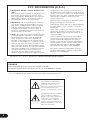
FCC INFORMATION (U.S.A.)
The exclamation point within the
equilateral triangle is intended to
alert the user to the presence of
important operating and maintenance
(servicing) instructions in the
literature accompanying the product.
The lightning flash with arrowhead
symbol, within the equilateral
triangle, is intended to alert the user
to the presence of uninsulated
“dangerous voltage” within the
product’s enclosure that may be of
sufficient magnitude to constitute a
risk of electrical shock.

3
WARNING-
When using any electrical or electronic prod-
uct, basic precautions should always be followed. These precau-
tions include, but are not limited to, the following:
1. Read all Safety Instructions, Installation Instructions,
Special Message Section items, and any Assembly Instructions
found in this manual BEFORE making any connections, includ-
ing connection to the main supply.
2. Do not attempt to service this product beyond that
described in the user-maintenance instructions. All other servic-
ing should be referred to qualified service personnel.
3. Main Power Supply Verification: Yamaha products are
manufactured specifically for the supply voltage in the area
where they are to be sold. If you should move, or if any doubt
exists about the supply voltage in your area, please contact your
dealer for supply voltage verification and (if applicable) instruc-
tions. The required supply voltage is printed on the name plate.
For name plate location, please refer to the graphic found in the
Special Message Section of this manual.
4. WARNING: Do not place this product or any other
objects on the power cord or place it in a position where anyone
could walk on, trip over, or roll anything over power or connect-
ing cords of any kind. The use of an extension cord is not
recommended! If you must use an extension cord, the minimum
wire size for a 25' cord (or less) is 18 AWG. NOTE: The smaller
the AWG number, the larger the current handling capacity. For
longer extension cords, consult a local electrician.
5. Ventilation: Electronic products, unless specifically
designed for enclosed installations, should be placed in locations
that do not interfere with proper ventilation. If instructions for
enclosed installations are not provided, it must be assumed that
unobstructed ventilation is required.
6. Temperature considerations: Electronic products should
be installed in locations that do not seriously contribute to their
operating temperature. Placement of this product close to heat
sources such as; radiators, heat registers etc., should be avoided.
7. This product was NOT designed for use in wet/damp
locations and should not be used near water or exposed to rain.
Examples of wet /damp locations are; near a swimming pool,
spa, tub, sink, or wet basement.
8. This product should be used only with the components
supplied or; a cart ,rack, or stand that is recommended by the
manufacturer. If a cart, rack, or stand is used, please observe all
safety markings and instructions that accompany the accessory
product.
9. The power supply cord (plug) should be disconnected
from the outlet when electronic products are to be left unused
for extended periods of time. Cords should also be disconnected
when there is a high probability of lightening and/or electrical
storm activity.
10. Care should be taken that objects do not fall and liquids
are not spilled into the enclosure through any openings that may
exist.
11. Electrical/electronic products should be serviced by a
qualified service person when:
a. The power supply cord has been damaged; or
b. Objects have fallen, been inserted, or liquids have been
spilled into the enclosure through openings; or
c. The product has been exposed to rain; or
d. The product does not operate, exhibits a marked change
in performance; or
e. The product has been dropped, or the enclosure of the
product has been damaged.
12. This product, either alone or in combination with an
amplifier and headphones or speaker/s, may be capable of
producing sound levels that could cause permanent hearing loss.
DO NOT operate for a long period of time at a high volume
level or at a level that is uncomfortable. If you experience any
hearing loss or ringing in the ears, you should consult an audi-
ologist.
IMPORTANT: The louder the sound, the shorter the time
period before damage occurs.
13. Some Yamaha products may have benches and/or acces-
sory mounting fixtures that are either supplied as a part of the
product or as optional accessories. Some of these items are
designed to be dealer assembled or installed. Please make sure
that benches are stable and any optional fixtures (where appli-
cable) are well secured BEFORE using. Benches supplied by
Yamaha are designed for seating only. No other uses are recom-
mended.
INFORMATION RELATING TO PERSONAL INJURY, ELECTRICAL SHOCK,
AND FIRE HAZARD POSSIBILITIES HAS BEEN INCLUDED IN THIS LIST.
IMPORTANT SAFETY INSTRUCTIONS
92-469-3
PLEASE KEEP THIS MANUAL

4

5
Thank you for purchasing the Yamaha MAGICSTOMP.
To get the most out of this product, we urge you to thoroughly
read this manual before use. Also, please keep the manual in a
safe place for future reference.
Owner’s Manual
GUITAR EFFECTS PROCESSOR
Contents
Precautions ............................................................................ 6
Package Contents .................................................................. 6
MAGICSTOMP’s Main Features ............................................... 7
Component Names & Functions............................................. 8
Top Panel ...................................................................................... 8
Rear Panel ..................................................................................... 8
Connections ......................................................................... 10
Using the MAGICSTOMP ...................................................... 12
Turn on the amplifier and play ..................................................... 12
Try out some of the other patches ............................................... 12
Create your own sound ........................................................ 14
Use the knobs to adjust the effect ................................................ 14
Saving Patches .....................................................................16
Storing edited patches (STORE) ................................................... 16
Giving the patch a name ..................................................... 18
Giving the patch a name (Name Edit Mode) ............................... 18
Tuner Mode .......................................................................... 20
Using the tuner ........................................................................... 20
Factory Set (Restore Factory Defaults) ................................ 21
Restoring the factory defaults ...................................................... 21
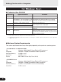
Editing Patches with a Computer ........................................ 22
Data Flow .................................................................................... 23
Using the Sound Editor for MAGICSTOMP .................................. 23
For Windows Users ........................................................................... 24
For Macintosh Users ......................................................................... 26
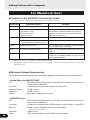
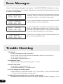
Error Messages ..................................................................... 28
Trouble Shooting ................................................................. 28
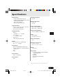
Specifications ....................................................................... 29
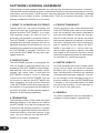
SOFTWARE LICENSING AGREEMENT ..................................... 30

6
Package Contents
The following items are included in the MAGICSTOMP package. Check to see that you have every-
thing listed here.
•MAGICSTOMP ............................... 1
• CD-ROM ......................................... 1
•Power Adaptor * .............................. 1
• USB Cable ...................................... 1
• Owner’s Manual (this booklet) ........ 1
• Patch List ........................................ 1
CAUTION
• Before breaking the seal on the CD-ROM package, please carefully read
the “Software Licensing Agreement” on page 30.
•Never attempt to play back the included CD-ROM on an audio CD player.
Doing so may result in damage to your hearing as well as to your CD
player/audio speakers.
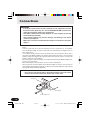
Precautions
•Avoid using the MAGICSTOMP in the following locations to prevent possible damage:
• In direct sunlight or next to heating equipment.
• In extremely cold or hot locations.
• Locations exposed to high humidity or excessive dust.
• Locations subject to strong shocks or vibration.
• Before making any connections, make sure that the power is switched OFF on the MAGICSTOMP
and any external devices.
•To protect speakers from possible damage, always set the VOLUME knob to “0” before switching
the power ON/OFF.
• When connecting any devices to this unit, make sure that the power is switched OFF first.
• Do not apply excessive force to the switches, knobs and controls.
• The MAGICSTOMP is a precision device. Handle it with care and avoid dropping or jarring it.
•For safety, always remove the power adaptor from the AC wall outlet if there is any danger of
lightning striking in your area.
•Keep the MAGICSTOMP away from neon signs or fluorescent lighting to prevent noise pickup.
•To prevent damage and possibly electrical shock, never open the case and tamper with the
internal circuitry.
• Never use benzene, thinner or other volatile liquids for cleaning, as these chemicals may cause
damage or discoloration to the finish. Always use a dry, soft cloth to wipe off dust and dirt.
* May not be included depending on your particular area. Please check with your Yamaha dealer.
05.11.17, 4:56 PMPage 6

7
MAGICSTOMP’s Main Features
[Harnessing the power of Yamaha’s DSP technology]
• The MAGICSTOMP utilizes a powerful 32-bit DSP designed by Yamaha to deliver amp simula-
tions and effects from the DG series amplifiers and DG, AG, and UD-Stomp effects. It also
produces a variety of digital effects derived from the Yamaha SPX series with unprecedented
audio quality and function.
[New algorithms deliver stunning effects and powerful amplifier simula-
tions for guitarists]
•New “Distortion & Amp type” effect creates a variety of sounds from overdrive to powerful fuzz
effects.
•New algorithms created by VCM (Virtual Circuitry Modeling) technology delivers vintage type
phaser and flanger effects.
[Professional quality preset tone patches make the MAGICSTOMP ready
to use out of the box]
• Close collaboration with artists from around the world have produced a variety of ready to use,
professional quality effects.
<<99 On-board preset patches + CD-ROM patch library>>
<<99 User patches allow editing and storing>>
[Feels and operates like a compact effector]
• Simple design and controls (4 knobs, 3 footswitches) provide guitarists with a familiar operating
environment. Operation is simple and straightforward to provide quick sound creation.
[Upload new patch data via USB]
•Patches supplied on the accompanying CD-ROM or downloaded from the internet can be up-
loaded into the MAGICSTOMP via the USB cable. You can also store customized sound patches
in your computer.
[Create custom effects on your computer with dedicated software based
patch editor]
• Use the supplied USB cable to connect the MAGICSTOMP to your computer, then use the
accompanying “Sound Editor For MAGICSTOMP” application to edit the effects parameters
and set parameters that can be controlled with the MAGICSTOMP’s three control knobs. Cre-
ate your own custom patches to make your own MAGICSTOMP.
[Built-in chromatic auto tuner]
• The MAGICSTOMP also includes a built-in chromatic auto tuner, which is extremely useful in
live performances and recording.

8
Component Names & Functions
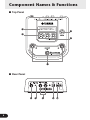
■ Top Panel
U99¤MAGICSTOMP
ó‡GAINfiMSTRáTONE
■ Rear Panel
q
w
t
e
r
yu
i
o!0

9
Component Names & Functions
q Display
Displays information for the currently selected patch or operating conditions of the MAGICSTOMP.
w CONTROL Knobs
These are used to control patch parameters. (→ page 14)
e VOLUME Knob
Controls the overall output volume of the MAGICSTOMP. (→ page 12)
r STORE Button
This button is used to store patches that have been edited in the MAGICSTOMP. (→ page 16)
t – Switch, + Switch, ON/OFF Switch
These switches select patches, switch the patch ON or OFF, or switch modes. (→ page 12, 13, 18,
20)
y INPUT Jack
For connecting an instrument such as a guitar, synthesizer, etc., to the MAGICSTOMP. (→ page 11)
u INPUT LEVEL HIGH/LOW Switch
Selects HIGH or LOW impedance to match the input level with the output level of the instrument
connected to the INPUT jack. (→ page 11)
i OUTPUT L/MONO, R Jacks
For connecting the MAGICSTOMP to a guitar amplifier, recorder, PA mixer, etc. Use the L/MONO
jack when connecting to monaural devices. (→ page 11)
o USB Jack
For connecting the MAGICSTOMP to a computer. This lets you edit patch voices on the computer or
move patch data between the computer and the MAGICSTOMP. (→ page 23)
!0 AC IN Jack (Power Adaptor)
Connect the power adaptor to this jack. (→ page 10)
*Power is switched ON when the power adaptor is connected (and supplying power) to the main unit.
05.11.16, 5:52 PMPage 9

10
Connections
CAUTION
• In order to prevent electric shock or damage to your equipment, turn OFF
the power on the guitar amp, etc., and set the MAGICSTOMP’s volume to its
minimum level before making any connections.
• Use ONLY a Yamaha AC-10 Power Adaptor (or other adaptor specifically
recommended by Yamaha).
Using another adaptor may result in damage, overheating or fire, which
can be very dangerous.
• Make sure to use the recommended AC voltage as indicated on the power
adaptor.
• The MAGICSTOMP automatically switches “ON” when power is connected and supplied to the
device.
• Connect a guitar, bass or any line level instrument such as a synthesizer, etc., to the INPUT
jack. The MAGICSTOMP can also be connected to the effect loop of an amplifier, mixer, or
other similar device.
• Set the INPUT LEVEL switch to match the output level of the instrument or device that is
connected to the MAGICSTOMP. If the sound is distorted when the switch is set to the HIGH
position, change the setting to LOW. If you feel output is low when the switch is set to the LOW
position, change the setting to HIGH.
•When using patches with stereo output, we recommend connecting the MAGICSTOMP’s out-
put jacks to a stereo device.
• When connecting to a monaural device, use the OUTPUT L/MONO jack.
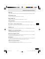
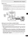
• When connecting the power adaptor to the MAGICSTOMP’s AC IN jack, you can wrap the
power adaptor cord around the cord hook as shown in the illustration below (this helps keeping
the plug from being accidentally pulled out).
CAUTION
• Don’t let the cord bend sharply or kink when wrapping the cord around
the hook. An excessive bend can cut the cord or start a fire.
Power adaptor cord
Cord hook
AC IN jack
05.11.16, 5:52 PMPage 10

11
INPUTAC IN
L/MONO
INPUT
OUTPUT
L/MONO R
R
L/MONO
INPUT
INPUT INPUT
INPUT
R
L/MONO
U99¤MAGICSTOMP
ó‡GAINfiMSTRáTONE
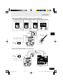
Guitar, or other
instrument
Power Adaptor
Connecting to a guitar
amplifier (monaural)
MAGICSTOMP
Connecting to guitar amplifiers
(stereo)
Connecting to a record-
ing device, etc.
Connections
● Using the MAGICSTOMP with a guitar or other instrument
● Using the MAGICSTOMP in an effect loop
INPUT
AC IN
OUTPUT
EFFECT
SEND
EFFECT
RETURN
L/MONO R
RL
U99¤MAGICSTOMP
ó‡GAINfiMSTRáTONE
Power Adaptor
MAGICSTOMP
Mixer, etc.
Electric
Outlet
Electric
Outlet
*The AC adaptor’s shape will
vary according to the country
to which the device is shipped.
*The AC adaptor’s shape will
vary according to the country
to which the device is shipped.
05.11.16, 5:52 PMPage 11

12
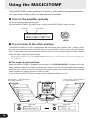
■ Try out some of the other patches
The MAGICSTOMP has a total of 198 patches. 99 of those are User Patches (U01 – U99) to which
you can save (overwrite) data of patches that you have created. The other 99 are Preset Patches
(P01 – P99) which can not be overwritten with new data. You can however, edit the Preset Patches
and save them in the User Patch section.
*When shipped from the factory, the MAGICSTOMP’s User Patch section contains the same data as found in the
Preset Patches.
● Two ways to select patches
When the MAGICSTOMP is shipped from the factory, its [UP/DOWN MODE] is already set for the
patch selection mode. In this mode, just press the + switch to move to the next greater patch number,
and press the – switch to move to the next lesser patch number. Hold either switch down and the
patch numbers will quickly cycle up or down in order.
In this mode, the ON/OFF switch is used to switch the patch (effect) on or off.
Using the MAGICSTOMP
U99¤MAGICSTOMP0
ó‡GAINfiMSTRáTONE
Patch No.
The MAGICSTOMP comes loaded with a variety of effect patches (programmed effects).
First, give some of the presets a try and see what’s available.
■ Turn on the amplifier and play
You’ll hear the currently selected patch.
Use the MAGICSTOMP’s VOLUME knob to adjust the MAGICSTOMP’s output volume.
U01¤DIST
ó‡GAINfiMSTRáTONE
U01¤DIST
ó EFFECT OFF
U98
P02
U01
U99
P01
U99
P01
P99
P98
P97
P99
U02
U03
U04
U01¤DIST
ó‡BAL0fiSTERáVOL
Effect ON
Effect OFF
Patch Name
Pressing the – switch decreases
the patch number by 1
Pressing the + switch increases
the patch number by 1

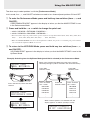
13
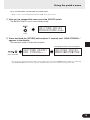
The other way to select patches is with the [Performance Mode].
In this mode, the –, +, and ON/OFF switches are used to turn three adjacent patches ON and OFF.
q To enter the Performance Mode, press and hold any two switches (from –, +, and
ON/OFF).
“PERFORMANCE MODE” appears in the display to inform you that the MAGICSTOMP is now
in the Performance Mode.
w Press and hold the – or + switch to change the patch set.
– switch: U01/02/03→P97/98/99→P94/95/96→…
+ switch: U01/02/03→U04/05/06→U07/08/09→…
*Patch sets (three adjacent patches make a patch set) have been predetermined. (U01, U02, U03), (U04, U05,
U06) …… (U97, U98, U99), (P01, P02, P03) …… (P97, P98, P99).
*When the MAGICSTOMP switches to the Performance Mode, the patch set containing the patch number
selected with the Up/Down Mode is selected.
e To return to the UP/DOWN Mode, press and hold any two switches (from –, +,
and ON/OFF).
“UP/DOWN MODE” appears in the display to inform you that the MAGICSTOMP is now in the
Up/Down Mode.
Example) Switching from the Up/Down Mode (patch U06 is selected) to the Performance Mode.
Using the MAGICSTOMP
U06¤AG0TUBE100
›ãBAL0ÄSTERÄVOL
U06¤AG0TUBE100
ó‡BALVfiSTERáVOL
Up/Down Mode
Performance Mode
Press and hold any two of the three
switches
U06¤AG0TUBE100
PERFORMANCE0MODE
Patch U04
ON/OFF switch
Patch U06
ON/OFF switch
Patch U05
ON/OFF switch
When in the Performance Mode, the lamp of the currently
selected patch lights (U05 is selected in the illustration below).
When all three patches are switched OFF, the
display appears as follows (all lamps are off).
U05¤AG0DYNAMIC2
›0OFF0(U04:05:06)
Press and hold
the – switch.
U01/02/03
P97/98/99
P94/95/96
P91/92/93
:
:
Press and hold
the + switch.
U07/08/09
U10/11/12
U13/14/15
U16/17/18
:
:

14
When the knob’s position does not match the value for the selected parameter, you’ll need to rotate
the knob until it matches the position that corresponds to the parameter value before you can change
the setting.
Let’s rotate the DRIV knob. Before rotating the knob, its parameter name is shown in the display.
[Fig. 1]
When the knob is rotated, the set value (8.9) is indicated in the display, and will not change until you
rotate the knob past the 3 o’clock position. [Fig. 2]
U01¤DI
ó‡DRIV
U01⁄DI
óñ10.0
U01⁄DI
óê06.2
U01⁄DIST10000000
ó‡DRIVfiMSTRáTONE
U01¤DI
ó‡08.9
U01¤DI
ó‡08.9
U01⁄DI
ó‡09.0
Create your own sound
■ Use the knobs to adjust the effect
The three knobs located below the display let you adjust different characteristics of the effect.
The parameters that these knobs adjust, differ according to the selected patch.
The name of the parameters that these knobs adjust, and the relative knob position of each of the
parameters are shown on the lower half of the display.
In the example shown below, the following parameter names and knob values are shown starting
with the left knob.
DRIV (Drive): 8.9, MSTR (Master): 4.0, TONE: 2.8
[Fig. 1] [Fig. 2]
[Fig. 3]
[Fig. 4]
After you rotate the knob past the 3 o’clock position, the actual value that corresponds to the knob’s
position is indicated in the display. Also, the ¤ mark to the right of the patch number will change to ⁄
to indicate that the parameter’s value has changed. [Fig. 3]
Once the parameter’s value has been changed, the value shown in the display will reflect the posi-
tion of the knob. [Fig. 4]
If the knob is not moved for a few seconds, the value display will return to the parameter name
display.

15
Create your own sound
OK, now try and edit a patch to your liking.
*Parameters for the patch(effect) can only be adjusted when the MAGICSTOMP is in its normal operating mode
(when a patch is selected and the effect is switched "ON"). Parameters can not be adjusted if the effect is switched
"OFF" or when the MAGICSTOMP is in the Store Mode (→page 16), Name Edit Mode (→page 18) or Tuner
Mode (→page 20).
Information on the parameters can be found in the PDF file in the accompanying CD-ROM. Look in
the (Macintosh only: [International] folder →) [Manual] folder → and get the [EffectListE.pdf]. This list
offers descriptions on each of the effect parameters.
* Acrobat Reader is required to view the PDF file on your computer. (→page 25, 27)
Could you make something you like?
If you did, you can use the store operation described in the next section to save your settings in the
MAGICSTOMP.
If you select another patch before carrying out the store operation, or disconnect the power, all
changes you made will be lost and the data will return to its original condition.
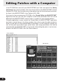
Inside the accompanying CD-ROM, you’ll find an editing application called “Sound
Editor for MAGICSTOMP” that lets you use a computer to edit the patches (effects)
in the MAGICSTOMP.
The MAGICSTOMP has a total of 63 different effect types, that each utilize a variety
of parameters in addition to the three that can be controlled with the MAGICSTOMP’s
three control knobs. With the Sound Editor you can change any of the effect’s pa-
rameters as you like, to create elaborate effects. You can also assign any param-
eters you like to the MAGICSTOMP’s three control knobs.
The Sound Editor also lets you use the patch library that is included in the accompa-
nying CD-ROM and store patches you have created with your computer, in the
MAGICSTOMP.
We also recommend that you use the “Sound Editor for MAGICSTOMP” to gain a
greater understanding of how the MAGICSTOMP works. Refer to page 22 for more
information.

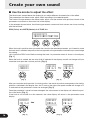
16
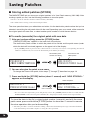
■ Storing edited patches (STORE)
The MAGICSTOMP lets you store your original patches in its User Patch memory (U01-U99). After
creating a patch you like, use the following procedure to store the patch.
*Patches can not be stored in the Preset Patch memory (P01-P99).
*The volume knob’s setting is not stored with patch data.
The store operation takes your edited data and writes it to the destination patch number that you’ve
selected, overwriting the old patch data with the new. Depending upon your needs, either overwrite
the original patch with new data, or select another patch number to store the new data to.
● To rewrite (overwrite) the original patch with new data
q After you’re done editing, press the [STORE] button.
“PRESS[STORE]1sec” appears in the lower half of the display.
The destination patch number to which the patch will be stored, and the patch name (under
which the data will be stored) appears on the upper half of the display.
* If the [STORE] button is pressed when a Preset Patch is currently selected, the corresponding User Patch
number is automatically selected as the destination patch number for storing.
w You can also give the patch a new name.
To change the name of the patch, follow steps w through r described on page 18.
e Press and hold the [STORE] button (about 1 second) until “NOW STORING...”
appears on the display.
P01⁄DIST10000000
ó‡DRIVfiMSTRáTONE
U01:DIST10000000
PRESS[STORE]1sec
U01:DIST10000000
PRESS[STORE]1sec
U01¤DIST10000000
NOW0STORING...
Store complete!
Press and hold
Saving Patches
Destination patch
number for storing
The name of the
edited patch
*To cancel the store operation, press and quickly release the [STORE] button (within 1 second) and the
MAGICSTOMP returns to its original condition (the changed patch name returns to its original name).
To store the data to the file’s original patch number (overwrite) and with the same
patch name, press and hold the [STORE] button for more than 1 second to execute
the store operation after you’re done editing.
*This store procedure can not be used when editing a Preset Patch. You must first assign a User Patch number
as the destination patch number before executing the store operation.

17
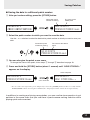
● Saving the data to a different patch number
q After you’re done editing, press the [STORE] button.
U11:DIST10000000
PRESS[STORE]1sec
Saving Patches
The name of the edited
patch
e You can also give the patch a new name.
To change the name of the patch, follow steps w through r described on page 18.
r Press and hold the [STORE] button (about 1 second) until “NOW STORING...”
appears on the display.
P01⁄DIST10000000
ó‡DRIVfiMSTRáTONE
U01:DIST10000000
PRESS[STORE]1sec
Destination patch
number for storing
The name of the
edited patch
w Select the patch number to which you want to save the data.
Use the – or + switches to select the destination patch number to which you want to save your
data.
U11:DIST10000000
PRESS[STORE]1sec
U11¤DIST10000000
NOW0STORING...
Store complete!
Press and hold
*To cancel the store operation, press and quickly release the [STORE] button (within 1 second) and the
MAGICSTOMP returns to its original condition (the changed patch name returns to its original name).
In additions to creating and storing new patches, you can use the store operation to put
patches in the same order that you use them in performance making selection while
playing quick and convenient.
Destination patch
number for storing

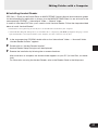
18
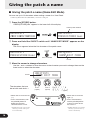
■ Giving the patch a name (Name Edit Mode)
You can use up to 12 characters when making a name for a User Patch.
* Names of Preset Patches (P01-P99) can not be changed.
q Press the [STORE] button.
“PRESS[STORE]1sec” appears in the lower half of the display.
w Press and hold the ON/OFF switch until “NAME EDIT MODE” appears on the
display.
The cursor appears below the first character of the patch name.
_
U01¤DIST10000000
NAME EDIT MODE
U01:DIST10000000
PRESS[STORE]1sec
Press and hold
U01¤DIST10000000
ó‡DRIVfiMSTRáTONE
U01:DIST10000000
PRESS[STORE]1sec
Current patch number
Cursor
e Move the cursor to change characters.
Use the – and + switches to move the cursor to the character you want to change, then use the
three knobs to select the character.
Giving the patch a name
_
U01¤TIST10000000
NAME EDIT MODE
Cursor
A to Z
(space)
a to z
(space)
0 to 9 : ! " #
$ % & ' ( ) *
+ ,- . / (space)
The characters that can
be set with each knob →
•Moves the cursor to the left
(←)
• Press simultaneously with
the [STORE] button to
delete the character
selected with the cursor.
* Holding down the switch (and
button) repeats the same opera-
tion continuously.
•Moves the cursor to the
right (→)
• Press simultaneously
with the [STORE] button
to insert a space where
the cursor is.
* Holding down the switch (and
button) repeats the same op-
eration continuously.

19
Up to 12 characters can be used in a patch name.
* Only 11 characters are displayed when the USB connection is used.
r After you’ve changed the name, press the ON/OFF switch.
The MAGICSTOMP is now in store standby mode.
Giving the patch a name
U01:TUBE0DRIVE1
PRESS[STORE]1sec
U01:TUBE0DRIVE1
NOW0STORING...
Changing the patch name is complete.
Press and hold
Press
t Press and hold the [STORE] button (about 1 second) until “NOW STORING...”
appears in the display.
The new patch name is stored with the patch.
U01¤TUBE0DRIVE1
ó‡DRIVfiMSTRáTONE
*To cancel the patch name edit operation, press and quickly release the [STORE] button (within 1 second) and
the MAGICSTOMP returns to its original condition (the patch name returns to its original name).

20
In Tune!
TUNE0PITCH:440Hz
E0:00000>|<
Raise Pitch
Lower Pitch
TUNE0PITCH:440Hz
00:000000|000000
Standard Pitch
Note Name
Tuner Mode
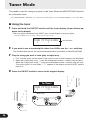
This mode is used for tuning your guitar. In the Tuner Mode, the MAGICSTOMP functions
as a chromatic tuner.
*The MAGICSTOMP’s OUTPUT jack is muted (no sound output) when the MAGICSTOMP is in the Tuner Mode.
■ Using the tuner
1 Press and hold the ON//OFF switch until the tuner display (shown below) ap-
pears on the display.
With your guitar connected to the INPUT jack, use the display to tune your guitar.
*The Tuner Mode is not available during the store operation.
2 If you want to use a standard pitch other than 440Hz, use the – or + switches.
The standard pitch can be set anywhere between 438Hz and 445Hz in the MAGICSTOMP.
3 Play the string you want to tune (play a single tone).
1. First, tune the guitar until the name of the note you want to tune to appears on the display.
2. When the string’s pitch is low, > mark will be displayed and the – switch’s lamp will be lit.
When the string’s pitch is high, < mark will be displayed and the + switch’s lamp will be lit.
The string’s pitch is in tune when “>|<” appears in the display and the ON/OFF switch’s
lamp is lit.
4 Press the ON/OFF switch to return to the original display.
00000>|
|00<
|0<
|000<
|<
000>00|
00>000|
0000>0|
A página está carregando ...
A página está carregando ...
A página está carregando ...
A página está carregando ...
A página está carregando ...
A página está carregando ...
A página está carregando ...
A página está carregando ...
A página está carregando ...
A página está carregando ...
A página está carregando ...
-
 1
1
-
 2
2
-
 3
3
-
 4
4
-
 5
5
-
 6
6
-
 7
7
-
 8
8
-
 9
9
-
 10
10
-
 11
11
-
 12
12
-
 13
13
-
 14
14
-
 15
15
-
 16
16
-
 17
17
-
 18
18
-
 19
19
-
 20
20
-
 21
21
-
 22
22
-
 23
23
-
 24
24
-
 25
25
-
 26
26
-
 27
27
-
 28
28
-
 29
29
-
 30
30
-
 31
31


Yamaha MagicStomp Manual do proprietário
- Categoria
- Programas
- Tipo
- Manual do proprietário
- Este manual também é adequado para
em outros idiomas
- español: Yamaha MagicStomp El manual del propietario
- français: Yamaha MagicStomp Le manuel du propriétaire
- italiano: Yamaha MagicStomp Manuale del proprietario
- English: Yamaha MagicStomp Owner's manual
- русский: Yamaha MagicStomp Инструкция по применению
- Nederlands: Yamaha MagicStomp de handleiding
- Deutsch: Yamaha MagicStomp Bedienungsanleitung
- dansk: Yamaha MagicStomp Brugervejledning
- čeština: Yamaha MagicStomp Návod k obsluze
- svenska: Yamaha MagicStomp Bruksanvisning
- polski: Yamaha MagicStomp Instrukcja obsługi
- Türkçe: Yamaha MagicStomp El kitabı
- română: Yamaha MagicStomp Manualul proprietarului