
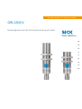
O P E R A T I N G I N S T R U C T I O N
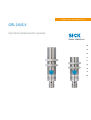
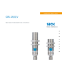
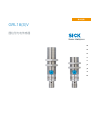
GRL18(S)V
Cylindrical photoelectric sensors
en, de, fr, pt, it, es, zh, ja, ru


Described product
GR18 Inox
GRL18(S)V
Manufacturer
SICK AG
Erwin-Sick-Str. 1
79183 Waldkirch
Germany
Production location
SICK, Malaysia
Legal information
This work is protected by copyright. Any rights derived from the copyright shall be
reserved for SICK AG. Reproduction of this document or parts of this document is only
permissible within the limits of the legal determination of Copyright Law. Any modifica‐
tion, abridgment or translation of this document is prohibited without the express writ‐
ten permission of SICK AG.
The trademarks stated in this document are the property of their respective owner.
© SICK AG. All rights reserved.
Original document
This document is an original document of SICK AG.
8021183 | SICK
Subject to change without notice
3

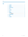
Contents
1 Safety notes....................................................................................... 5
2 Intended use...................................................................................... 5
3 Operating and status indicators...................................................... 5
4 Mounting............................................................................................. 6
5 Electrical installation........................................................................ 7
6 Commissioning.................................................................................. 8
7 Troubleshooting................................................................................. 10
7.1 Troubleshooting table............................................................................... 10
8 Disassembly and disposal............................................................... 11
9 Maintenance...................................................................................... 11
10 Technical specifications................................................................... 12
CONTENTS
4
8021183 | SICK
Subject to change without notice

1 Safety notes
■
Read the operating instructions before commissioning.
■
Connection, mounting, and setting may only be performed by skilled per‐
son.
■
Not a safety component in accordance with the EU Machinery Directive.
■
Power supply: Class 2
Enclosure type 1
■
When commissioning, protect the device from moisture and contamination.
■
These operating instructions contain information required during the life cycle of
the sensor.
2 Intended use
The GRL18(S)V is an opto-electronic photoelectric retro-reflective sensor (referred to as
“sensor” in the following) for the optical, non-contact detection of objects, animals, and
persons. A reflector is required for this product to function. If the product is used for any
other purpose or modified in any way, any warranty claim against SICK AG shall become
void.
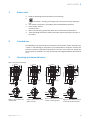
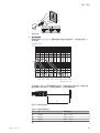
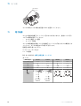
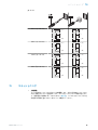
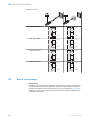
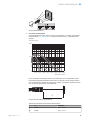
3 Operating and status indicators
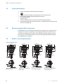
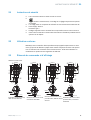
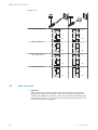
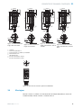
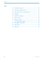
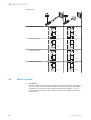
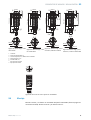
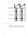
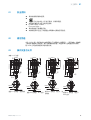
Table 1: Dimensional drawings
55.9 (2.2)
M18x1
31.7 (1.25)
4
(0.16)
12.9
(0.51)
2
2.8 (0.11)
2.2 (0.09)
3
67
5
1
M18x1
Figure 1: Short variant, con‐
necting cable
55.9 (2.2)
31.7 (1.25)
4
(0.16)
12.9
(0.51)
M12x1
M18x1
2
3
5
1
2.8 (0.11)
2.2 (0.09)
67
M18x1
Figure 2: Short variant, M12
male connector
27.8 (1.09)
55.9 (2.2)
31.7 (1.25)12.9
(0.51)
4
(0.16)
M18x1
2
3
4
5
1
2.8 (0.11)
2.2 (0.09)
67
M18x1
Figure 3: Short variant, potenti‐
ometer, connecting cable
12.9
(0.51)
4
(0.16)
55.9 (2.2)
31.7 (1.25)
27.8 (1.09)
M12x1
M18x1
2
3
4
5
1
2.8 (0.11)
2.2 (0.09)
67
M18x1
Figure 4: Short variant, potenti‐
ometer, M12 male connector
SAFETY NOTES 1
8021183 | SICK
Subject to change without notice
5

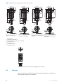
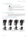
73.3 (2.89)
49.3 (1.94)
4
(0.16)
12.9
(0.51)
M18x1
2
3
5
1
2.8 (0.11)
2.2 (0.09)
67
M18x1
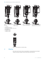
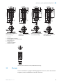
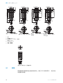
Figure 5: Long variant, connect‐
ing cable
73.4 (2.89)
49.3 (1.94)
M12x1
M18x1
2
3
5
1
4
(0.16)
12.9
(0.51)
2.8 (0.11)
2.2 (0.09)
67
M18x1
Figure 6: Long variant, M12
male connector
73.3 (2.89)
49.3 (1.94)
45.3 (1.78)
4
(0.16)
12.9
(0.51)
M18x1
2
3
4
5
1
2.8 (0.11)
2.2 (0.09)
67
M18x1
Figure 7: Long variant, potenti‐
ometer, connecting cable
73.4 (2.89)
49.3 (1.94)
45.3 (1.78)
4
(0.16)
M18x1
2
3
4
5
1
M12x1
12.9
(0.51)
2.8 (0.11)
2.2 (0.09)
67
M18x1
Figure 8: Long variant, potenti‐
ometer, M12 male connector
1
Connection
2
Mounting bracket M18 x 1
3
Fastening nuts (2 x); WS24, stainless steel
4
Potentiometer, 270°
5
LED indicator (4 x)
6
Optical axis, receiver
7
Optical axis, sender
+
–
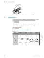
Figure 9: Operating element: sensitivity setting
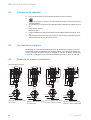
4 Mounting
Mount the sensor and the reflector using suitable mounting brackets (see the SICK
range of accessories). Align the sensor and reflector with each other.
3 OPERATING AND STATUS INDICATORS
6
8021183 | SICK
Subject to change without notice

max. 90 Nm
Note the sensor’s maximum permissible tightening torque of 90 Nm.
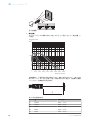
5 Electrical installation
The sensors must be connected in a voltage-free state (U
V
= 0 V). The following informa‐
tion must be observed, depending on the connection type:
– Male connector connection: pin assignment
– Cable: wire color
Only apply voltage/switch on the voltage supply (U
V
> 0 V) once all electrical connec‐
tions have been established. The green LED indicator lights up on the sensor.
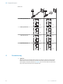
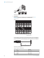
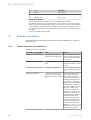
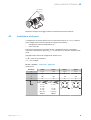
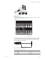
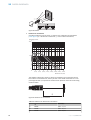
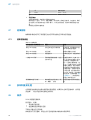
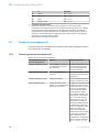
Explanations of the connection diagram (Tables 2 and 3):
Q / Q = switching outputs
n. c. = not connected
DC: 10... 30 V DC, see „Technical specifications“, page 12
Table 2: DC
GRL18(S)V x11xxx x13xxx x24xxx x23xxx
1 + (L+) + (L+) + (L+) + (L+)
2
Q
n. c.
Q
n. c.
3 - (M) - (M) - (M) - (M)
4 Q Q Q Q
1 = brn
2 = wht
3 = blu
4 = blk
0.14 mm
2
AWG26
1 = brn
-
3 = blu
4 = blk
0.14 mm
2
AWG26
1
2
4 3
1
2
4 3
ELECTRICAL INSTALLATION 5
8021183 | SICK
Subject to change without notice
7

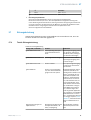
Table 3: DC
PNP: Q (≤ 100 mA)
+ (L+)
Q
– (M)
+ (L+)
Q
– (M)
NPN: Q (≤ 100 mA)
+ (L+)
Q
– (M)
+ (L+)
Q
– (M)
PNP: Q (≤ 100 mA)
+ (L+)
Q
– (M)
+ (L+)
Q
– (M)
NPN: Q (≤ 100 mA)
+ (L+)
Q
– (M)
+ (L+)
Q
– (M)
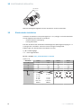
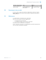
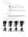
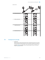
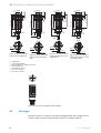
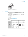
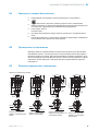
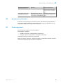
6 Commissioning
1 Alignment
Align the sensor with a suitable reflector. Select the position so that the red emitted light
beam hits the center of the reflector. The sensor must have a clear view of the reflector,
with no object in the path of the beam [see figure]. You must ensure that the optical open‐
ings of the sensor and reflector are completely clear.
6 COMMISSIONING
8
8021183 | SICK
Subject to change without notice

Figure: Alignment
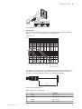
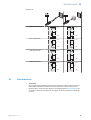
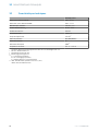
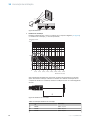
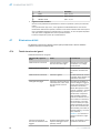
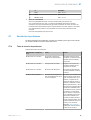
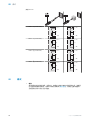
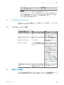
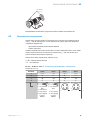
2 Sensing range
Adjust the distance between the sensor and the reflector according to the corresponding
diagram [ see figure 0] (x = sensing range, y = operating reserve).
1
0 1
(3.28)
2
(6.56)
3
(9.84)
4
(13.12)
5
(16.40)
6
(19.69)
7
(22.97)
8
(26.25)
100
10
Operating reserve
Distance in m (feet)
x
y
1
2
3
4
5
6
After alignment is complete, move a non-transparent object into the path of the beam. Use
and Table 3 to check the function. If the switching output fails to behave in accordance
with Table 3, check the application conditions. See section Fault diagnosis.
1
2
Figure 10: sensing range areas
Table 4: Definition of sensing range
2
GRL18(S)V
1
PL80A 0.03 ... 7.2 m
2
PL40A 0.03 ... 6.2 m
3
PL20A 0.03 ... 3.8 m
4
P250 0.03 ... 6.4 m
COMMISSIONING 6
8021183 | SICK
Subject to change without notice
9

2
GRL18(S)V
5
PL22 0.03 ... 2.2 m
6
REF-Plus 3436 0.06 ... 2.0 m
3 Sensitivity setting
Sensor which it is not possible to set: The sensor is adjusted and ready for operation.
The sensitivity is adjusted with the potentiometer (type: 270°). Clockwise rotation: operat‐
ing reserve increased; counterclockwise rotation: operating reserve reduced. We recom‐
mend setting the potentiometer to “Maximum”. A lower operating reserve may be neces‐
sary for depolarizing surfaces.
The sensor is adjusted and ready for operation.
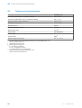
7 Troubleshooting
The Troubleshooting table indicates which measures are to be taken if the sensor stops
working.
7.1 Troubleshooting table
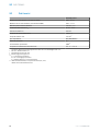
Table 5: Troubleshooting
LED indicator/fault pattern Cause Measures
Green LED does not light up No voltage or voltage below
the limit values
Check the power supply,
check all electrical connec‐
tions (cables and plug connec‐
tions)
Green LED does not light up Voltage interruptions Ensure there is a stable power
supply without interruptions
Green LED does not light up Sensor is faulty If the power supply is OK,
replace the sensor
Yellow LED flashes Sensor is still ready for opera‐
tion, but the operating condi‐
tions are not ideal
Check the operating condi‐
tions: Fully align the beam of
light (light spot) with the
reflector / Clean the optical
surfaces (sensor and reflec‐
tor) / Readjust the sensitivity
(potentiometer) / If the poten‐
tiometer is set to the max.
sensitivity: Reduce the dis‐
tance between the sensor and
the reflector, and check the
reflector type / Reflector is not
suitable for the application in
question (we recommend only
using SICK reflectors)/ Check
sensing range and adjust if
necessary, see table 4. / Dis‐
tance between the sensor and
the reflector is too long
Signal interruptions when
object is detected
Depolarizing property of the
object surface (e.g., tape),
reflection
Reduce sensitivity or change
the position of the sensor
7 TROUBLESHOOTING
10
8021183 | SICK
Subject to change without notice

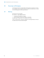
8 Disassembly and disposal
The sensor must be disposed of according to the applicable country-specific regula‐
tions. Efforts should be made during the disposal process to recycle the constituent
materials (particularly precious metals).
9 Maintenance
SICK sensors are maintenance-free.
We recommend doing the following regularly:
•
Clean the external lens surfaces
•
Check the screw connections and plug-in connections
No modifications may be made to devices.
Subject to change without notice. Specified product properties and technical data are
not written guarantees.
DISASSEMBLY AND DISPOSAL 8
8021183 | SICK
Subject to change without notice
11

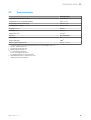
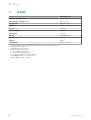
10 Technical specifications
GRL18(S)-xxxxxV
Sensing range (with reflector PL80A) 0.06 ... 6.0 m
Sensing range max. (with reflector PL80A) 0.03 ... 7.2 m
Light spot diameter/distance 175 mm / 7 m
Supply voltage V
S
DC 10 ... 30 V
2
Output current I
max.
100 mA
Max. switching frequency 1,000 / s
5
Max. response time <0.5 ms
6
Enclosure rating IP67,IP68,IP69K
11
Protection class III
8
Circuit protection A,B,D
10
Ambient operating temperature -25 °C ... + 55 °C
2
Grenzwerte; Betrieb im kurzschlussgeschützten Netz max. 8 A; Restwelligkeit max. 5 V
ss
5
Mit Hell- / Dunkelverhältnis 1:1
6
Signallaufzeit bei ohmscher Last
8
Bemessungsspannung DC 50 V
10
A = U
V
-Anschlüsse verpolsicher
B = Ein- und Ausgänge verpolsicher
D = Ausgänge überstrom- und kurzschlussfest
11
IP68: according to EN 60529 (water depth of 10 m / 24 h).
IP69K: according to ISO 20653:2013-03.
10 TECHNICAL SPECIFICATIONS
12
8021183 | SICK
Subject to change without notice


Beschriebenes Produkt
GR18 Inox
GRL18(S)V
Hersteller
SICK AG
Erwin-Sick-Str. 1
79183 Waldkirch
Deutschland
Fertigungsstandort
SICK, Malaysia
Rechtliche Hinweise
Dieses Werk ist urheberrechtlich geschützt. Die dadurch begründeten Rechte bleiben
bei der Firma SICK AG. Die Vervielfältigung des Werks oder von Teilen dieses Werks ist
nur in den Grenzen der gesetzlichen Bestimmungen des Urheberrechtsgesetzes zuläs‐
sig. Jede Änderung, Kürzung oder Übersetzung des Werks ohne ausdrückliche schriftli‐
che Zustimmung der Firma SICK AG ist untersagt.
Die in diesem Dokument genannten Marken sind Eigentum ihrer jeweiligen Inhaber.
© SICK AG. Alle Rechte vorbehalten.
Originaldokument
Dieses Dokument ist ein Originaldokument der SICK AG.
14
8021183 | SICK
Subject to change without notice

Inhalt
11 Sicherheitshinweise.......................................................................... 16
12 Bestimmungsgemäße Verwendung............................................... 16
13 Bedien- und Anzeigeelemente........................................................ 16
14 Montage.............................................................................................. 17
15 Elektronische Installation................................................................ 18
16 Inbetriebnahme................................................................................. 19
17 Störungsbehebung............................................................................ 21
17.1 Tabelle Störungsbehebung....................................................................... 21
18 Demontage und Entsorgung............................................................ 22
19 Wartung.............................................................................................. 22
20 Technische Daten.............................................................................. 23
INHALT
8021183 | SICK
Subject to change without notice
15

11 Sicherheitshinweise
■
Vor der Inbetriebnahme die Betriebsanleitung lesen.
■
Anschluss, Montage und Einstellung nur durch Fachpersonal.
■
Kein Sicherheitsbauteil gemäß EU-Maschinenrichtlinie.
■
Power supply: Class 2
Enclosure type 1
■
Gerät bei Inbetriebnahme vor Feuchte und Verunreinigung schützen.
■
Diese Betriebsanleitung enthält Informationen, die während des Lebenszyklus des
Sensors notwendig sind.
12 Bestimmungsgemäße Verwendung
Die GRL18(S)V ist eine optoelektronische Reflexions-Lichtschranke (im Folgenden Sen‐
sor genannt) und wird zum optischen, berührungslosen Erfassen von Sachen, Tieren
und Personen eingesetzt. Zur Funktion wird ein Reflektor benötigt. Bei jeder anderen
Verwendung und bei Veränderungen am Produkt verfällt jeglicher Gewährleistungsan‐
spruch gegenüber der SICK AG.
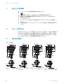
13 Bedien- und Anzeigeelemente
Tabelle 6: Maßzeichnungen
55.9 (2.2)
M18x1
31.7 (1.25)
4
(0.16)
12.9
(0.51)
2
2.8 (0.11)
2.2 (0.09)
3
67
5
1
M18x1
Abbildung 11: Kurzbauform,
Anschlussleitung
55.9 (2.2)
31.7 (1.25)
4
(0.16)
12.9
(0.51)
M12x1
M18x1
2
3
5
1
2.8 (0.11)
2.2 (0.09)
67
M18x1
Abbildung 12: Kurzbauform,
Stecker M12
27.8 (1.09)
55.9 (2.2)
31.7 (1.25)12.9
(0.51)
4
(0.16)
M18x1
2
3
4
5
1
2.8 (0.11)
2.2 (0.09)
67
M18x1
Abbildung 13: Kurzbauform,
Poti, Anschlussleitung
12.9
(0.51)
4
(0.16)
55.9 (2.2)
31.7 (1.25)
27.8 (1.09)
M12x1
M18x1
2
3
4
5
1
2.8 (0.11)
2.2 (0.09)
67
M18x1
Abbildung 14: Kurzbauform,
Poti, Stecker M12
11 SICHERHEITSHINWEISE
16
8021183 | SICK
Subject to change without notice

73.3 (2.89)
49.3 (1.94)
4
(0.16)
12.9
(0.51)
M18x1
2
3
5
1
2.8 (0.11)
2.2 (0.09)
67
M18x1
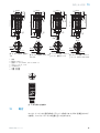
Abbildung 15: Langbauform,
Anschlussleitung
73.4 (2.89)
49.3 (1.94)
M12x1
M18x1
2
3
5
1
4
(0.16)
12.9
(0.51)
2.8 (0.11)
2.2 (0.09)
67
M18x1
Abbildung 16: Langbauform,
Stecker M12
73.3 (2.89)
49.3 (1.94)
45.3 (1.78)
4
(0.16)
12.9
(0.51)
M18x1
2
3
4
5
1
2.8 (0.11)
2.2 (0.09)
67
M18x1
Abbildung 17: Langbauform,
Poti, Anschlussleitung
73.4 (2.89)
49.3 (1.94)
45.3 (1.78)
4
(0.16)
M18x1
2
3
4
5
1
M12x1
12.9
(0.51)
2.8 (0.11)
2.2 (0.09)
67
M18x1
Abbildung 18: Langbauform,
Poti, Stecker M12
1
Anschluss
2
Befestigungsgewinde M18 x 1
3
Befestigungsmutter (2 x); WS24, Edelstahl
4
Potentiometer, 270°
5
Anzeige-LED (4 x)
6
Optikachse, Empfänger
7
Optikachse, Sender
+
–
Abbildung 19: Bedienelement: Empfindlichkeitseinstellung
14 Montage
Sensor und Reflektor an geeignete Befestigungswinkel montieren (siehe SICK-Zubehör-
Programm). Sensor und Reflektor zueinander ausrichten.
BEDIEN- UND ANZEIGEELEMENTE 13
8021183 | SICK
Subject to change without notice
17

max. 90 Nm
Maximal zulässiges Anzugsdrehmoment des Sensors von 90 Nm beachten.
15 Elektronische Installation
Anschluss der Sensoren muss spannungsfrei (U
V
= 0 V) erfolgen. Je nach Anschlussart
sind die folgenden Informationen zu beachten:
– Steckeranschluss: Pinbelegung
– Leitung: Adernfarbe
Erst nach Anschluss aller elektrischen Verbindungen die Spannungsversorgung (U
V
> 0
V) anlegen bzw. einschalten. Am Sensor leuchtet die grüne Anzeige-LED.
Erläuterungen zum Anschlussschema (Tabellen 2 und 3):
Q / Q = Schaltausgänge
n. c. = nicht angeschlossen
DC: 10... 30 V DC, siehe „Technische Daten“, Seite 23
Tabelle 7: DC
GRL18(S)V x11xxx x13xxx x24xxx x23xxx
1 + (L+) + (L+) + (L+) + (L+)
2
Q
n. c.
Q
n. c.
3 - (M) - (M) - (M) - (M)
4 Q Q Q Q
1 = brn
2 = wht
3 = blu
4 = blk
0.14 mm
2
AWG26
1 = brn
-
3 = blu
4 = blk
0.14 mm
2
AWG26
1
2
4 3
1
2
4 3
15 ELEKTRONISCHE INSTALLATION
18
8021183 | SICK
Subject to change without notice

Tabelle 8: DC
PNP: Q (≤ 100 mA)
+ (L+)
Q
– (M)
+ (L+)
Q
– (M)
NPN: Q (≤ 100 mA)
+ (L+)
Q
– (M)
+ (L+)
Q
– (M)
PNP: Q (≤ 100 mA)
+ (L+)
Q
– (M)
+ (L+)
Q
– (M)
NPN: Q (≤ 100 mA)
+ (L+)
Q
– (M)
+ (L+)
Q
– (M)
16 Inbetriebnahme
1 Ausrichtung
Sensor auf geeigneten Reflektor ausrichten. Positionierung so wählen, dass der rote Sen‐
delichtstrahl in der Mitte des Reflektors auftrifft. Der Sensor muss freie Sicht auf den
Reflektor haben, es darf sich kein Objekt im Strahlengang befinden [siehe Abbildung]. Es
ist darauf zu achten, dass die optischen Öffnungen von Sensor und Reflektor vollständig
frei sind.
INBETRIEBNAHME 16
8021183 | SICK
Subject to change without notice
19

Abbildung: Ausrichtung
2 Schaltabstand
Distanz zwischen Sensor und Reflektor mit dem zugehörigen Diagramm [ siehe
Abbildung 0] abgleichen (x = Schaltabstand, y = Funktionsreserve).
1
0 1
(3.28)
2
(6.56)
3
(9.84)
4
(13.12)
5
(16.40)
6
(19.69)
7
(22.97)
8
(26.25)
100
10
Operating reserve
Distance in m (feet)
x
y
1
2
3
4
5
6
Nach durchgeführter Ausrichtung ein nicht-transparentes Objekt in den Strahlengang füh‐
ren. Zur Überprüfung der Funktion und Tabelle 3 heranziehen. Verhält sich der Schaltaus‐
gang nicht gemäß Tabelle 3, Einsatzbedingungen prüfen. Siehe Abschnitt Fehlerdiagnose.
1
2
Abbildung 20: Schaltabstand
Tabelle 9: Definition Schaltabstand
2
GRL18(S)V
1
PL80A 0,03 ... 7,2 m
2
PL40A 0,03 ... 6,2 m
3
PL20A 0,03 ... 3,8 m
4
P250 0,03 ... 6,4 m
16 INBETRIEBNAHME
20
8021183 | SICK
Subject to change without notice
A página está carregando...
A página está carregando...
A página está carregando...
A página está carregando...
A página está carregando...
A página está carregando...
A página está carregando...
A página está carregando...
A página está carregando...
A página está carregando...
A página está carregando...
A página está carregando...
A página está carregando...
A página está carregando...
A página está carregando...
A página está carregando...
A página está carregando...
A página está carregando...
A página está carregando...
A página está carregando...
A página está carregando...
A página está carregando...
A página está carregando...
A página está carregando...
A página está carregando...
A página está carregando...
A página está carregando...
A página está carregando...
A página está carregando...
A página está carregando...
A página está carregando...
A página está carregando...
A página está carregando...
A página está carregando...
A página está carregando...
A página está carregando...
A página está carregando...
A página está carregando...
A página está carregando...
A página está carregando...
A página está carregando...
A página está carregando...
A página está carregando...
A página está carregando...
A página está carregando...
A página está carregando...
A página está carregando...
A página está carregando...
A página está carregando...
A página está carregando...
A página está carregando...
A página está carregando...
A página está carregando...
A página está carregando...
A página está carregando...
A página está carregando...
A página está carregando...
A página está carregando...
A página está carregando...
A página está carregando...
A página está carregando...
A página está carregando...
A página está carregando...
A página está carregando...
A página está carregando...
A página está carregando...
A página está carregando...
A página está carregando...
A página está carregando...
A página está carregando...
A página está carregando...
A página está carregando...
A página está carregando...
A página está carregando...
A página está carregando...
A página está carregando...
A página está carregando...
A página está carregando...
A página está carregando...
A página está carregando...
A página está carregando...
-
 1
1
-
 2
2
-
 3
3
-
 4
4
-
 5
5
-
 6
6
-
 7
7
-
 8
8
-
 9
9
-
 10
10
-
 11
11
-
 12
12
-
 13
13
-
 14
14
-
 15
15
-
 16
16
-
 17
17
-
 18
18
-
 19
19
-
 20
20
-
 21
21
-
 22
22
-
 23
23
-
 24
24
-
 25
25
-
 26
26
-
 27
27
-
 28
28
-
 29
29
-
 30
30
-
 31
31
-
 32
32
-
 33
33
-
 34
34
-
 35
35
-
 36
36
-
 37
37
-
 38
38
-
 39
39
-
 40
40
-
 41
41
-
 42
42
-
 43
43
-
 44
44
-
 45
45
-
 46
46
-
 47
47
-
 48
48
-
 49
49
-
 50
50
-
 51
51
-
 52
52
-
 53
53
-
 54
54
-
 55
55
-
 56
56
-
 57
57
-
 58
58
-
 59
59
-
 60
60
-
 61
61
-
 62
62
-
 63
63
-
 64
64
-
 65
65
-
 66
66
-
 67
67
-
 68
68
-
 69
69
-
 70
70
-
 71
71
-
 72
72
-
 73
73
-
 74
74
-
 75
75
-
 76
76
-
 77
77
-
 78
78
-
 79
79
-
 80
80
-
 81
81
-
 82
82
-
 83
83
-
 84
84
-
 85
85
-
 86
86
-
 87
87
-
 88
88
-
 89
89
-
 90
90
-
 91
91
-
 92
92
-
 93
93
-
 94
94
-
 95
95
-
 96
96
-
 97
97
-
 98
98
-
 99
99
-
 100
100
-
 101
101


em outras línguas
- français: SICK GRL18(S)V Mode d'emploi
- italiano: SICK GRL18(S)V Istruzioni per l'uso
- 日本語: SICK GRL18(S)V 取扱説明書
Artigos relacionados
-
SICK GRL18(S)V Instruções de operação
-
-
-
-
-
-
-
-
-
