
If you have questions or comments, contact us.
Pour toute question ou tout commentaire, nous contacter.
Si tiene dudas o comentarios, contáctenos.
Dúvidas? Visite-nos na Internet em www.D
eWALT.com.br
1-800-4-DeWALT
Instruction Manual
Guide d’utilisation
Manual de instrucciones
Manual de Instruções
DW074LR, DW079LR, DW079LG
Rotary Laser
Laser rotatif
Láser rotativo
Laser Rotativo
Final page size: A5 (148mm x 210mm)
DW074_DW079 User Manual - NA - TRANSLATED.indd 1 5/17/2018 2:05:26 PM

English 8
Français 18
Español 29
Português 40
DW074_DW079 User Manual - NA - TRANSLATED.indd 2 5/17/2018 2:05:26 PM

24
25
745
9
2
11
3 61 8
12
DW079LR/DW079LG
74
9
2
11
3 61 8
12
DW074LR
RPM
15
˚/45˚/90˚
X
Y
7
6
2
5
3
4
A
B
3
DW074_DW079 User Manual - NA - TRANSLATED.indd 3 5/17/2018 2:05:27 PM

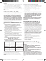
15
LEVEL MODE
MODE NIVEAU
MODO DE NIVEL
MODO DE
NIVELAMENTO
PLUMB MODE
MODE APLOMB
MODO DE PLOMADA
MODO NIVELAMENTO
VERTICAL
LEVEL MODE/MODE NIVEAU/MODO DE NIVEL/
MODO DE NIVELAMENTO
PLUMB MODE/MODE APLOMB /MODO DE PLOMADA/
MODO NIVELAMENTO VERTICAL
5/8-11"
5/8-11"
20
20
C
D
E F
4
DW074_DW079 User Manual - NA - TRANSLATED.indd 4 5/17/2018 2:05:28 PM

21
26
27
28
53
54
22
22
30
30
23
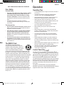
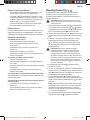
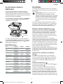
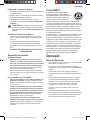
INDICATORS/INDICATEURS /INDICADORES/INDICADORES
Above Grade/
Au-dessus du niveau /
Por encima del nivel
Acima do grau
Slightly Above Grade/
Légèrement au-dessus du niveau /
Ligeramente por encima del nivel/
Ligeiramente acima do grau
On Grade/
Au niveau /
En nivel/
Um grau
Slightly below Grade/
Légèrement au-dessous du niveau /
Ligeramente por debajo del nive/
Ligeiramente abaixo do graul
Below Grade/
Au-dessous du niveau /
Por debajo del nivel/
Abaixo do grau
audible signals/
signal sonore /
señales auditivas/
sinais audíveis
fast beep /
bip rapide /
bip rápido/
Bipe rápido
fast beep /
bip rapide /
bip rápido/
Bipe rápido
steady tone/
tonalité constante /
tono constante/
Tom estável
slow beep/
bip lent /
bip lento/
Bipe lento
slow beep/
bip lent /
bip lento/
Bipe lento
display icons/
icône affichée /
íconos en pantalla/
ícones da tela
G
H
I
J
5
DW074_DW079 User Manual - NA - TRANSLATED.indd 5 5/17/2018 2:05:29 PM

33
32
47
42
42
43
45
45
41
39
37
40
40
44
44
46
46
M
K
L
N
6
DW074_DW079 User Manual - NA - TRANSLATED.indd 6 5/17/2018 2:05:30 PM

BEAM
FAISCEAU
RAYO
RAIO
A
B
L
Marks on walls
Repères sur les murs
Marcas en la pared
Marcas na parede
LASER UNIT ROTATED 180˚
ROTATION DE L’APPAREIL LASER A 180˚
UNIDAD LÁSER ROTADA EN 180º
UNIDADE DE LASER EM ROTAÇÃO DE 180º
BEAM
FAISCEAU
RAYO
RAIO
BB
L
AA
O
P
Q R
7
DW074_DW079 User Manual - NA - TRANSLATED.indd 7 5/17/2018 2:05:31 PM

English
ENGLISH
8
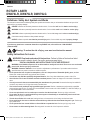
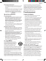
Definitions: Safety Alert Symbols and Words
This instruction manual uses the following safety alert symbols and words to alert you to hazardous situations and your risk of
personal injury or property damage.
DANGER: Indicates an imminently hazardous situation which, if not avoided, will result in death or serious injury.
WARNING: Indicates a potentially hazardous situation which, if not avoided, could result in death or serious injury.
CAUTION: Indicates a potentially hazardous situation which, if not avoided, may result in minor or moderate injury.
(Used without word) Indicates a safety related message.
NOTICE: Indicates a practice not related to personal injury which, if not avoided, may result in property damage.
If you have any questions or comments about this or any
DeWALT
tool, call us toll free at: 1-800-4-
DeWALT
(1-800-433-9258).
Warning: To reduce the risk of injury, user must read instruction manual.
Safety Instructions for Lasers
WARNING! Read and understand all instructions. Failure to follow all instructions listed
below may result in electric shock, fire and/or serious personal injury.
SAVE ALL WARNINGS AND INSTRUCTIONS FOR FUTURE REFERENCE
WARNING! Laser Radiation Exposure. Do not disassemble or modify the laser level. There are no user serviceable
parts inside. Serious eye injury could result.
WARNING: Hazardous Radiation. Use of controls or adjustments or performance of procedures other than those
specified herein may result in hazardous radiation exposure.
• Do not operate the laser in explosive atmospheres, such as in the presence of flammable liquids, gases, or dust.
Power tools create sparks which may ignite the dust or fumes.
• Use the laser only with the specifically designated batteries. Use of any other batteries may create a risk of fire.
• Store idle laser out of reach of children and other untrained persons. Lasers are dangerous in the hands of untrained
users.
• Use only accessories that are recommended by the manufacturer for your model. Accessories that may be suitable for
one laser, may create a risk of injury when used on another laser.
• Tool service must be performed only by qualified repair personnel. Service or maintenance performed by unqualified
personnel may result in injury. To locate your nearest
DeWALT
service center call 1–800–4-
DeWALT
(1–800–433–9258) or go
to http://www.
DeWALT
.com on the Internet.
• Do not use optical tools such as a telescope or transit to view the laser beam. Serious eye injury could result.
• Do not place the laser in a position which may cause anyone to intentionally or unintentionally stare into the laser
beam. Serious eye injury could result.
• Turn the laser off when it is not in use. Leaving the laser on increases the risk of staring into the laser beam.
• Do not position the laser near a reflective surface which may reflect the laser beam toward anyone’s eyes. Serious eye
injury could result.
• Do not operate the laser around children or allow children to operate the laser. Serious eye injury may result.
• Do not remove or deface warning labels. Removing labels increases the risk of exposure to radiation.
ROTARY LASER
DW074LR, DW079LR, DW079LG
DW074_DW079 User Manual - NA - TRANSLATED.indd 8 5/17/2018 2:05:31 PM

ENGLISH
9
• Position the laser securely on a level surface. Damage to the laser or serious injury could result if the laser falls.
WARNING: Use of controls or adjustments or performance of procedures other than those specified herein may result in
hazardous radiation exposure.
WARNING! DO NOT DISASSEMBLE THE ROTARY LASER. There are no user serviceable parts inside.
Disassembling the rotary laser will void all warranties on the product. Do not modify the product in any way.
Modifying the tool may result in hazardous laser radiation exposure.
• The label on your tool may include the following symbols.
V ........................volts
mW ....................milliwatts
........ laser warning symbol
nm..........wavelength in nanometers
3R .......... Class 3R Laser
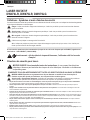
Warning Labels
For your convenience and safety, the following label is on your laser.
WARNING: To reduce the risk of injury, user must read instruction manual.
WARNING: LASER RADIATION. DO NOT STARE INTO BEAM. Class 3R Laser Product
AVOID EXPOSURE -LASER RADIATION IS EMITTED FROM THIS APERTURE
DW074_DW079 User Manual - NA - TRANSLATED.indd 9 5/17/2018 2:05:32 PM

ENGLISH
10
Laser Information
The DW074LR and DW079LR/LG Cordless Rotary Lasers are
CLASS 3R laser products and comply with 21 CFR 1040.10
and 1040.11 except for deviations pursuant to laser notice
No. 50, dated June 24, 2007.
Conforms to UL STDS 61010-1 & 2595
Certified to CSA STD C22.2 No. 61010-1
Complies with IEC 60825-1:2014
These devices comply with Part 15 of the FCC Rules.
Operation is subject to the following two conditions: 1) this
device may not cause harmful interference, and 2) this device
must accept any interference received, including interference
that may cause undesired operation.
NOTE: This equipment has been tested and found to comply
with the limits for a Class B digital device, pursuant to Part
15 of the FCC Rules. These limits are designed to provide
reasonable protection against harmful interference in a
residential installation. This equipment generates, uses and
can radiate radio frequency energy and, if not installed and
used in accordance with the instructions, may cause harmful
interference to radio communications. However, there is
no guarantee that interference will not occur in a particular
installation. If this equipment does cause harmful interference
to radio and television reception, which can be determined by
turning the equipment off and on, the user is encouraged to
try to correct the interference by one or more of the following
measures:
• Reorient or relocate the receiving antenna.
• Increase the separation between the equipment and
receiver.
• Connect the equipment into an outlet on a circuit
differentfrom that which the receiver is connected.
• Consult the dealer or an experienced radio/TV technician
for help.
Canada, Industry Canada (IC) Notices
Class B digital circuitry of this device complies with Canadian
ICES-003. This device complies with Industry Canada license-
exempt RSS standard(s). Operation is subject to the following
two conditions: 1) this device may not cause interference,
and 2) this device must accept any interference, including
interference that may cause undesired operation of the device.
READ ALL INSTRUCTIONS
Batteries and Power
This
DeWALT
rotary laser will accept all
DeWALT
20 volt
lithium ion batteries, but is built to best resist damage during a
fall when used with the following batteries: All 1.5Ah and 2Ah
DeWALT
20 volt lithium ion batteries.
Charging the Battery
The battery pack is not fully charged out of the carton. You
need to use a
DeWALT
20 volt charger to charge the battery
pack before you can use the rotary laser.
• Refer to the chart at the end of this manual for compatibility
of chargers and battery packs.
• Be sure to read all safety instructions before using your
charger.
WARNING:
• DO NOT attempt to charge the battery pack
with any chargers other than the ones listed
in this manual. The charger and battery pack are
specifically designed to work together.
• Carefully follow all instructions and warnings on
the battery label and package and accompanying
Battery Safety Manual.
1. Slide the battery pack into the charger as described in the
Battery Safety Manual.
2. Wait until the battery pack is fully charged.
3. Slide the battery pack out of the track.
NOTE: When ordering replacement battery packs, be sure to
include the catalog number and voltage.
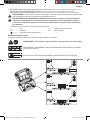
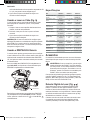
Installing the 20V
DeWALT
Battery Pack
1. Position the fully-charged 20V
DeWALT
battery pack so the
release button (Figure
E
15
) is facing away from you and
to the right.
2. Press and hold down the release button on the battery
pack.
3. Slide the battery pack all the way into the track on the side
of the laser.
4. Release the button on the battery pack.
Removing the Battery Pack
1. Press and hold the release button on the battery pack.
2. Slide the battery pack out of the track on the laser.
3. Release the button on the battery pack.
4. To recharge the battery pack, insert it into the charger, as
described in the Battery Safety Manual.
WARNING: Batteries can explode or leak, and can
cause injury or fire. To reduce this risk, follow the
instructions in the Battery Safety Manual.
Storing Battery Packs
• The best storage place is one that is cool and dry, and
away from direct sunlight and excess heat or cold.
• Long storage will not harm the battery pack or charger.
Under proper conditions, they can be stored for 5 years
or more.
DW074_DW079 User Manual - NA - TRANSLATED.indd 10 5/17/2018 2:05:32 PM

ENGLISH
11
SAVE THESE INSTRUCTIONS FOR FUTURE USE
User Safety
Personal Safety
• Stay alert, watch what you are doing, and use common
sense when operating a laser product. Do not use
the tool while tired or under the influence of drugs,
alcohol, or medication. A moment of inattention while
operating laser products may result in serious personal
injury.
• Use appropriate personal protective equipment,
including eye protection when working in a construction
environment.
Tool Use and Care
• Do not use the tool if the switch does not turn it on or
off. Any tool that cannot be controlled with the switch is
dangerous and must be repaired.
• Store idle laser products out of the reach of children
and do not allow persons unfamiliar with the laser
product or these instructions to operate the laser
product. Laser products are dangerous in the hands of
untrained users.
• Use only accessories that are recommended by the
manufacturer for your model. Accessories that may be
suitable for one tool, may become hazardous when used
with another tool.
The RBRC® Seal
The RBRC® (Rechargeable Battery
Recycling Corporation) Seal on the nickel
cadmium, nickel metal hydride or lithium-ion
batteries (or battery packs) indicates that the
costs to recycle these batteries (or battery
packs) at the end of their useful life have already been paid
by
DeWALT
. In some areas, it is illegal to place spent nickel
cadmium, nickel metal hydride or lithium-ion batteries in the
trash or municipal solid waste stream and the Call 2 Recycle®
program provides an environmentally conscious alternative.
Call 2 Recycle, Inc., in cooperation with
DeWALT
and other
battery users, has established the program in the United
States and Canada to facilitate the collection of spent nickel
cadmium, nickel metal hydride or lithium-ion batteries. Help
protect our environment and conserve natural resources by
returning the spent nickel cadmium, nickel metal hydride or
lithium-ion batteries to an authorized
DeWALT
service center
or to your local retailer for recycling. You may also contact
your local recycling center for information on where to drop off
the spent battery. RBRC® is a registered trademark of Call 2
Recycle, Inc.
Operation
Operating Tips
• To extend battery life per charge, turn the laser off when it
is not in use.
• To ensure the accuracy of your work, check the laser
calibration often. Refer to Calibrating the Laser.
• Before attempting to use the laser, make sure the tool is
positioned on a relatively smooth, secure surface.
• Always mark the center of the laser line or dot. If you
mark different parts of the beam at different times you will
introduce error into your measurements.
• To increase working distance and accuracy, set up the
laser in the middle of your working area.
• When attaching to a tripod or wall, mount the laser
securely.
• When working indoors, a slow rotary head speed will
produce a visibly brighter line, a faster rotary head speed
will produce a visibly solid line.
• To increase beam visibility, wear Laser Enhancement
Glass es and/or use a Laser Target Card to help find the
beam.
• Extreme temperature changes can cause movement or
shifting of building structures, metal tripods, equipment,
etc., which can effect accuracy. Check your accuracy often
while working.
• When working with the
DeWALT
Digital Laser Detector, set
the laser’s rotation speed to the fastest setting.
• If the laser is dropped or has suffered a sharp blow, have
the calibration system checked by a qualified service
center before using the laser.
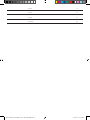
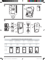
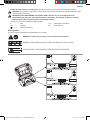
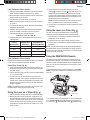
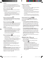
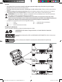
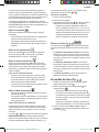
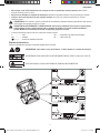
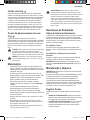
Control Panel (Fig.
A
,
B
)
The laser is primarily controlled by the power button
1
, the
mode button
2
, the speed button
3
and the scan mode button
4
. These features are then modified when used with either the
Axis selection button
5
(DW079LR/LG in Slope mode only), or
the two direction/elevation adjustment buttons
6
and
7
.
The direction/elevation adjustment buttons control the rotational
direction of the laser head as well as adjust the elevation of the
beam when the unit is in slope mode. These buttons can also
be used to incrementally rotate the beam when the unit is in
Scan mode.
The buttons on the DW074LR control panel, DW079LR/
DW079LG control panel, and the DW079LR/DW079LG Remote
keypad all work the same, unless otherwise indicated.
DW074_DW079 User Manual - NA - TRANSLATED.indd 11 5/17/2018 2:05:32 PM

ENGLISH
12
Power Button
The Power button is used to turn the laser unit on and off.
• To power ON the DW074LR or DW079LR/LG laser unit,
press the Power button once.
• To completely power OFF the DW074LR or DW079LR/LG
laser unit, press the power button for 3 sec.
Speed/Rotation Button
The speed button
3
is used to adjust the rotation speed of the
laser beam through its 4 preset speeds (150, 300, 600, and
1200 RPM).
Scan Mode Button
15˚/45˚/90˚
The scan mode button
4
is used to make the laser head
sweep back and forth, creating a short, bright laser line. This
short line is much brighter and more visible than when the unit
is in full rotation mode.
Using Scan Mode
• To enter Scan Mode, push and release the scan mode
button
4
. To cycle through the scan angles, continue to
press the button until you reach the desired angle.
• The direction of the scan zone can be controlled with the
arrow buttons
6
and
7
.
Slope Mode Button
• To activate Slope Mode press the slope mode button
2
.
• To return to self-leveling mode and re-engage full self-
leveling, press and hold the mode button
2
again.
Setting the Slope Direction
When Slope Mode is activated, the unit automatically engages
the X- Axis. This allows you to slope the laser in the direction of
the X-Axis, as indicated by the “gunsights” on the rollcage.
The LED light
11
or
12
indicates the current slope direction.
DW079LR/LG only: In certain situations, it may be desirable
to slope the laser in the Y-axis. The direction of Slope Mode
can be changed back and forth between the Y-axis and the
X-axis by pressing the X-Y axis button
5
. The selected axis is
identified by LED light
24
or
25
.
Setting the Amount of Slope
1. Turn on Slope Mode.
2. Select the desired axis.
3. Use the Arrow buttons (Fig.
B
,
6
and
7
) to tilt the laser
rotor head up and down.
- Each quick press of an Arrow button will move the slope
by 0.01º (1/16" @ 30ft. or 1.6mm @ 10m).
- If you press and hold an Arrow button between 2 sec-
10 sec, the slope will move from .0.01º/sec to 0.2º/sec.
- If you press and hold an Arrow button longer than 10
sec, the slope will move 0.2º/sec.
Arrow Buttons (Fig.
B
,
R
)
The arrow buttons (
B
6
and
7
) are used for different
functions depending on the operating mode of the laser unit.
• In Self-Leveling Horizontal Mode, the arrow buttons
rotate the direction of the laser beam clockwise or counter-
clockwise during rotation, or adjust the position of the laser
beam clockwise or counter-clockwise during Scan Mode.
• In Self-Leveling Vertical Mode, the arrow buttons rotate
the direction of the laser beam clockwise or counter-
clockwise during rotation, or adjust the position of the laser
beam clockwise or counter-clockwise during Scan Mode.
• In Slope Mode, the arrow buttons are used to tilt the
laser head.
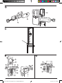
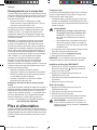
Turning the Laser On (Fig.
E
,
B
)
1. Insert the fully charged 20V battery pack as shown in
Figure
E
.
2. Gently press the power button
1
to power ON the laser.
- The power LED indicator light
9
will illuminate
- Self-leveling mode is activated automatically and
the laser unit will self-level. Once the laser unit is
level, the beam will rotate once at 600 RPM in the
clockwise direction.
- After 10 sec., Hi Mode (Anti- Drift) is activated
automatically and the Hi LED
8
will illuminate.
3. Press the speed/rotation button
3
to adjust the rotation
speed. The direction can be changed using buttons
6
and
7
.
4. Press the Scan button
4
to set the laser to scan in 0°, 15°,
45°, or 90° degree mode.
If you turn ON Slope Mode, the Slope LED
(
12
)
will light. If using
X-axis leveling, the X-axis LED
(
24
)
will light, or if using Y-axis
leveling, the Y-axis LED
(
25
)
will light instead.
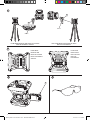
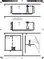
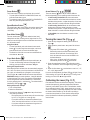
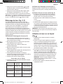
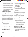
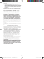
Calibrating the Laser (Fig. O, P)
Field calibration checks should be done frequently. This section
provides instructions for performing simple field calibration
checks of your
DeWALT
Rotary Laser. Field calibration checks
do not calibrate the laser. That is, these checks do not correct
errors in the leveling or plumbing capability of the laser. Instead,
the checks indicate whether or not the laser is providing a
correct level and plumb line. These checks cannot take the
place of professional calibration performed by a
DeWALT
service center.
DW074_DW079 User Manual - NA - TRANSLATED.indd 12 5/17/2018 2:05:33 PM

ENGLISH
13
Level Calibration Check (X-axis)
1. Set up a tripod between two walls that are at least 50 feet
apart. The exact location of the tripod is not critical.
2. Mount the laser unit on the tripod so that the X-axis points
directly toward one of the walls.
3. Turn the laser unit on and allow it to self-level.
4. Mark and measure points A and B on the walls as shown
in Figure O.
5. Turn the entire laser unit 180º so the X-axis points directly
toward the opposite wall.
6. Allow the laser unit to self-level, and mark and measure
points AA and BB on the walls as shown in Figure P.
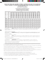
7. Calculate the total error using the equation:
Total Error = (AA – A) – (BB– B)
8. Compare total error to the allowable limits shown in the
following table.
Distance
Between Walls
Allowable Error
DW074LR
Allowable Error
DW079LR/DW079LG
40 ft. 3/32" 3/64"
50 ft. 1/8" 1/16"
70 ft. 5/32" 3/32"
100 ft. 1/4" 1/8"
Level Calibration Check (Y-axis)
Repeat the procedure above, but with the laser unit positioned
so the Y-axis is pointed directly toward the walls.
Plumb Error Check (Fig. Q)
1. Using a standard plumb bob as a reference, mark the top
and bottom of a wall. (Be sure to mark the wall and not the
floor and ceiling.)
2. Position the rotary laser securely on the floor approximately
3' (1 m) from the wall.
3. Turn the laser on, and point the dot at the mark on the
bottom of the wall. Then, using the up/down arrows on the
remote control, rotate the dot upwards. If the center of the
dot scans over the mark on the top of the wall, the laser is
properly calibrated.
NOTE: This check should be done with a wall no shorter than
the tallest wall for which this laser will be used.
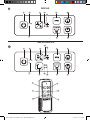
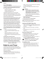
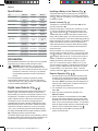
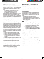
Using the Laser on a Tripod (Fig.
C
)
1. Position the tripod securely and set it to the desired height.
2. Make sure that the top of the tripod is roughly level. The
laser will self-level only if the top of the tripod is within ± 5˚
of level. If the laser is set up too far out of level, it will beep
when it reaches the limit of its leveling range. No damage
will be done to the laser, but it will not operate in an “out of
level” condition.
3. Secure the laser to the tripod by attaching the tripod
adapter
20
as shown in Figure
C
to the laser body. The
adapter may be assembled to the bottom for level mode
or to the side for plumb mode. Place the assembly on the
tripod and screw the threaded knob on the tripod into the
female thread on the tripod adapter.
NOTE: Be sure that the tripod you are working with has a
5/8"–11 threaded screw to ensure secure mounting.
4. Turn the laser on and adjust the rotation speed and controls
as desired.
Using the Laser on a Floor (Fig.
D
)
The laser level can be positioned directly on the floor for
leveling and plumbing applications such as framing walls.
1. Place the laser on a relatively smooth and level surface
where it will not be disturbed.
2. Position the laser for a level or plumb setting as shown.
3. Turn the laser on and adjust the rotation speed and controls
as desired.
NOTE: The laser will be easier to set up for wall applications if
the rotation speed is set to 0 RPM and if the remote control is
used to line up the laser with control marks. The remote allows
one person to set up the laser.
Using the DW079LR/LG Remote
The remote control allows one person to operate and set up
the laser from a distance. The LED light on the remote control
indicates a signal is being transmitted from the DW079LR/LG
laser unit. You can use all the buttons on the keypad to control
that laser unit.
If your DW079LR/LG laser unit was stamped on or after 2016-
49-NZ, you can use the Remote to completely power OFF the
laser unit.
2016-49-NZ
2016-49-NZ
>
To completely power OFF a DW079LR/LG laser unit (stamped
on or after 2016-49-NZ) using the Remote keypad, press the
X-Y axis button
(
14
)
and the MODE button
(
13
)
simultaneously.
DW074_DW079 User Manual - NA - TRANSLATED.indd 13 5/17/2018 2:05:34 PM

ENGLISH
14
Specifications
SKU DW074LR DW079LR DW079LG
Laser Wavelength 630-680nm 630-680nm 515-530nm
630-680nm
Laser Power/Class ≤5mw /
CLASS 3R
≤ 5mw /
CLASS 3R
≤ 5mw /
CLASS 3R
Rotation Speed 150, 300, 600,
1200 RPM
150, 300, 600,
1200 RPM
150, 300, 600,
1200 RPM
Self-Leveling Range ± 5° ± 5° ± 5°
Indoor Visibile Range 150' (45 m)
diameter
200' (60 m)
diameter
250' (80 m)
diameter
Range with Detector 1500' (450 m)
diameter
2000' (600 m)
diameter
2000' (600 m)
diameter
Leveling Accuracy
(@ 600 RPM)
± 1/8" per 100' (±
3 mm per 30 m)
± 1/16” per 100’
(± 1.5 mm per
30m
± 1/16” per 100’
(± 1.5 mm per
30m
Power Source 20V D
e
WALT
batteries
20V D
e
WALT
batteries
20V D
e
WALT
batteries
Operating Temperature 23°F to 122°F
(-5°C to 50°C)
23°F to 122°F
(-5°C to 50°C)
23°F to 122°F
(-5°C to 50°C)
Storage Temperature -4°F to 158°F
(-20°C to 70°C)
-4°F to 158°F
(-20°C to 70°C)
-4°F to 158°F
(-20°C to 70°C)
Environmental Water resistant Water resistant Water resistant
Accessories
Recommended accessories for use with your tool are available
for purchase at your factory-owned local service center.
WARNING: Since accessories, other than those
offered by
DeWALT
, have not been tested with this
product, use of such accessories with this tool could be
hazardous. To reduce the risk of injury, only
DeWALT
,
recommended accessories should be used with this
product.
If you need assistance in locating any accessory, please
contact
DeWALT
Industrial Tool Co., 701 East Joppa Road,
Towson, MD 21286, call 1–800–4-
DeWALT
(1–800–433–9258)
or visit our website www.
DeWALT
.com
Digital Laser Detector (Fig.
H
–
K
)
Some laser kits include a
DeWALT
Digital Laser Detector. The
DeWALT
Digital Laser Detector allows you to locate a laser
beam emitted by a rotary laser in bright light conditions or over
long distances. The detector can be used in both indoor and
outdoor situations where it is difficult to see the laser beam.
The detector is not for use with non-rotating lasers but is
compatible with most rotary red-beam (DW0743R) and green
beam (DW0743G) lasers. It can be set to indicate the location
of the beam to either the nearest 1/8" (3 mm) or the nearest
1/25" (1 mm). The detector gives both visual signals through
the display window
22
and audio signals through the speaker
23
to indicate the location of the laser beam.
The
De
WALT Digital Laser Detector can be used with or without
the detector clamp. When used with the clamp, the detector can
be positioned on a grade rod, leveling pole, stud or post.
Installing a Battery in the Detector (Fig.
H
)
The Digital Laser Detector is powered by a 9 volt battery. To
install the battery provided, lift up on the battery compartment
cover
21
. Place the 9 volt battery in the compartment, aligning
the battery as shown.
Detector Controls (Fig.
I
)
The detector is controlled by the power button
26
and the
accuracy mode button
27
.
When the power button is pushed once, the detector is turned
on. The top of the display window shows the accuracy icon
27
, and the volume icon
28
. To decrease the volume of the
audible signal that the detector emits when it senses a laser
beam, push the button again; one of the half circles next to the
horn icon will dissappear. To turn off the audible signal push the
button a third time; the volume icon will dissapear. The
DeWALT
Digital Laser Detector also has an auto shut-off feature. If a
rotary laser beam does not strike the beam detection window,
or if no buttons are pressed, the detector will shut itself off in
about 30 minutes.
When the detector is on, the top of the window shows an
accuracy mode icon. Either the ±1/25" (1 mm) accuracy mode
icon
53
will appear, or the ±1/8" (3 mm) accuracy mode icon
54
will appear. When the ±1/25" (1 mm) accuracy mode icon
appears, it indicates that the detector will give an “on grade”
reading only when the laser beam is on grade or no more
than 1/25" (1 mm) above or below it. When the 1/8" (3 mm)
accuracy mode icon appears, it indicates that the detector will
give an “on grade” reading when the laser beam is on grade
or approximately 1/8" (3 mm) above or below it. Push the
accuracy mode button
27
once to change the accuracy mode.
Detector Operation (Fig.
I
,
J
)
1. Set up and position the rotary laser that you will be using
according to the manufacturer’s directions. Turn the laser
on and make sure that the laser is rotating and emitting a
laser beam. NOTE: This detector has been designed to be
used only with a rotating laser. The detector will not work
with a stationary beam laser level.
2. Turn the detector on by pressing the power/volume
button
26
.
3. Adjust the volume as desired as described in the
Detector Controls.
4. Position the detector so that the detector window
22
is
facing the laser beam produced by the rotary laser. Move
the detector up or down within the approximate area of the
beam, until you have centered the detector. For information
about the display window indicators and the audible signal
indicators, refer to the table titled Indicators (Fig.
J
).
5. Use the marking notches
30
to accurately mark the
position of the laser beam.
DW074_DW079 User Manual - NA - TRANSLATED.indd 14 5/17/2018 2:05:34 PM

ENGLISH
15
Detector Cleaning and Storage
• Dirt and grease may be removed from the exterior of the
detector using a cloth or soft, non-metallic brush.
• The D
eWALT
Digital Laser Detector is waterproof. If you
should drop the detector in mud, wet concrete, or a similar
substance, simply hose the detector off. Do not use high
pressure water, e.g., from a pressure washer.
• The best storage place is one that is cool and dry–away
from direct sunlight and excess heat or cold.
Detector Service
Except for batteries, there are no user serviceable parts in the
Digital Laser Detector. Do not disassemble the unit. Unauth-
orized tampering with the laser detector will void all warranties.
Detector Troubleshooting
The detector will not turn on.
• Press and release the power/volume button.
• Check to see that the battery is in place and in the
proper position.
• If the detector is very cold, allow it to warm up in a
heated area.
• Replace the 9 volt battery. Turn the unit on.
• If the detector still does not turn on, take the detector to a
DeWALT
service center.
The detector’s speaker makes no sound.
• Ensure that the detector is on.
• Press the power/volume button. It will toggle from high, to
low, to mute.
• Ensure that the rotary laser is spinning and that it is emitting
a laser beam.
• If the detector is still not making any sound, take it to a
DeWALT
service center.
The detector does not respond to a stationary laser beam.
The
DeWALT
Digital Laser Detector has been designed to work
only with rotary lasers.
The detector gives off a tone but the LCD display window
does not function.
• If the detector is very cold, allow it to warm up in a
heated area.
• If the LCD display window is still not functioning, take the
detector to a
DeWALT
service center.
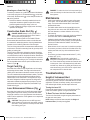
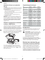
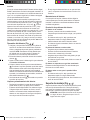
Mounting Bracket (Fig.
M
,
N
)
Some laser kits include a Wall Mount. It can be used for
attaching the tool to track or ceiling angle and to aid in
acoustical ceiling installation. Follow the directions below for
using the wall mount.
CAUTION: Before attaching the laser level to wall
track or ceiling angle, be sure that the track or angle is
properly secured.
1. Place the laser on the mounting base
37
aligning the 5/8–
11 screw hole on the tripod adapter (
20
, Fig.
C
) attached
to the bottom of the laser with the hole
39
in the mounting
base. Turn the mounting knob
40
to secure the laser.
2. With the wall mount measuring scale
41
facing you, loosen
the wall mount clamp locking knob
42
to open the clamp
jaws.
3. Position the clamp jaws around the wall track or ceiling
angle and tighten the wall mount clamp locking knob
42
to close the clamp jaws onto the track. Be sure that
the wall mount clamp locking knob is securely tightened
before proceeding.
CAUTION: Always use a ceiling wire hanger or
equivalent material, in addition to the wall mount
clamp locking knob, to help secure the laser level
while mounting it to a wall. Thread the wire through
the handle of the laser level. DO NOT thread the wire
through the protective metal cage. Additionally, screws
may be used to fasten the wall mount directly to the
wall as a back up. Screw holes
43
are located at the
top of the wall mount.
4. Using the base leveling knob
44
approximate a level
position from the wall.
5. The tool can be adjusted up and down to the desired offset
height for working. To change the height, loosen the locking
knob
45
located on the left of the wall mount. Support the
mounting base when adjusting the height.
6. Turn the adjustment knob
46
, located to the right of the
wall mount, to move the laser level up and down to set your
height. Use the wall mount measuring scale
41
to pinpoint
your mark.
NOTE: It may be helpful to turn the power on and turn the
rotary head so that it puts a dot on one of the laser scales.
The
DeWALT
target card is marked at 1–1/2" (38 mm),
therefore, it may be easiest to set the offset of the laser to
1–1/2" (38 mm) below the track.
7. Once you have positioned the laser at the desired height,
tighten the locking knob
45
to maintain this position.
DW074_DW079 User Manual - NA - TRANSLATED.indd 15 5/17/2018 2:05:34 PM

ENGLISH
16
Mounting on a Grade Rod (Fig.
K
)
To secure your detector to a grade rod, first attach the detector
to the clamp using the 1/4"-20 threaded knob
47
on the back
of the clamp. Slide the tracks
32
on the clamp around the rail
33
on the grade rod.
1. Position the detector at the height needed and turn the
clamp knob clockwise to tighten the jaws of the clamp
around the grade securing the clamp on the rod.
2. To make adjustments in height, slightly loosen the clamp,
reposition and retighten.
Construction Grade Rod (Fig.
L
)
DANGER: NEVER attempt to use a grade rod in a
storm or near overhanging electric wires. Death or
serious personal injury will occur.
Some laser kits include a grade rod. The
DeWALT
Grade
Rod is marked with measurement scales on both sides and
is constructed in telescoping sections. A spring-loaded button
actuates a lock to hold the grade rod at various lengths.
The front of the grade rod has the measurement scale starting
at the bottom. Use this for measuring from the ground up when
grading or leveling jobs.
The back of the grade rod is designed to measure the height
of ceilings, joists, etc. Fully extend the top section of the grade
rod until the button locks into the previous section. Extend that
section either until it locks into the adjacent section or until the
grade rod touches the ceiling or joist. The height is read where
the last extended section exits the previous lower section, as
shown in Figure
L
.
Target Card (Fig.
G
)
Some laser kits include a Laser Target Card to aid in locating
and marking the laser beam. The target card enhances the
visibility of the laser beam as the beam crosses over the card.
The card is marked with standard and metric scales. The laser
beam passes through the red plastic and reflects off of the
reflective tape on the reverse side. The magnet at the top of
the card is designed to hold the target card to ceiling track or
steel studs to determine plumb and level positions. For best
performance when using the Target Card, the
DeWALT
logo
should be facing you.
Laser Enhancement Glasses (Fig.
F
)
Some laser kits include a pair of Laser En hancement Glasses.
These glasses improve the visibility of the laser beam under
bright light conditions or over long distances when the laser is
used for interior applications. These glasses are not required to
operate the laser.
CAUTION: These glasses are not ANSI approved
safety glasses and should not be worn while operating
other tools. These glasses do not keep the laser beam
from entering your eyes.
DANGER: To reduce the risk of serious personal injury,
never stare directly into the laser beam, with or without
these glasses.
Maintenance
• Under some conditions, the glass lens may collect some
dirt or debris. This will affect beam quality and operating
range. The lens should be cleaned with a cotton swab
moistened with water.
• The flexible rubber shield can be cleaned with a wet lint-
free cloth such as a cotton cloth. USE WATER ONLY — DO
NOT use cleansers or solvents. Allow the unit to air dry
before storing.
• To maintain the accuracy of your work, check the calibration
of the laser often. Refer to Calibrating the Laser.
• Calibration checks and other maintenance repairs can be
performed by
DeWALT
service centers. Two free calibration
checks are included under the D
eWALT
One Year Free
Service Con tract.
• When the laser is not in use, store it in the kit box provided.
• Do not store your laser in the kit box if the laser is wet. Dry
exterior parts with a soft, dry cloth and allow the laser to
air dry.
• Do not store your laser at temperatures below 0˚F (-18˚C)
or above 105˚F (41˚C).
WARNING: Never use solvents or other harsh
chemicals for cleaning the non-metallic parts of the
tool. These chemicals may weaken the materials used
in these parts. Use a cloth dampened only with water
and mild soap. Never let any liquid get inside the unit;
never immerse any part of the unit into a liquid. Never
use compressed air to clean the laser.
Troubleshooting
Height of Instrument Alert
The DW074LR and DW079LR/LG have a built-in alarm feature
that alerts the operator if the unit is disturbed after the unit has
self-leveled. The laser unit will stop rotating, the control panel
LED indicator light will flash, and the beeper will sound.
Turning the Laser Off
Press the the power button for 3 sec to turn the laser off. The
power LED indicator light will no longer be illuminated.
To Reset The Laser Unit for Continued Use
Turn the unit off and back on again using the power button on
the laser unit control panel.
NOTE: Always recheck the laser setup after the Height of
Instrument Alert (Hi mode) has triggered.
DW074_DW079 User Manual - NA - TRANSLATED.indd 16 5/17/2018 2:05:34 PM

ENGLISH
17
Service and Repairs
NOTE: Disassembling the laser level will void all warranties on
the product.
To assure product SAFETY and RELIABILITY, repairs,
maintenance and adjustment should be performed by
authorized service centers. Service or maintenance performed
by unqualified personnel may result in a risk of injury. To locate
your nearest D
eWALT
service center call 1–800–4-
DeWALT
(1–800–433–9258) or visit our website: www.
DeWALT
.com.
Register Online
Thank you for your purchase. Register your product now for:
• WARRANTY SERVICE: Registering your product will help
you obtain more efficient warranty service in case there is a
problem with your product.
• CONFIRMATION OF OWNERSHIP: In case of an
insurance loss, such as fire, flood or theft, your registration
of ownership will serve as your proof of purchase.
• FOR YOUR SAFETY: Registering your product will allow
us to contact you in the unlikely event a safety notification is
required under the Federal Consumer Safety Act.
Register online at www.dewalt.com/register.
Three Year Limited Warranty
DeWALT
will repair, without charge, any defects due to faulty
materials or workmanship for three years from the date of
purchase. This warranty does not cover part failure due to
normal wear or tool abuse. For further detail of warranty
coverage and warranty repair information, visit www.
DeWALT
.
com or call 1–800–4-
DeWALT
(1–800–433–9258). This
warranty does not apply to accessories or damage caused
where repairs have been made or attempted by others. This
warranty gives you specific legal rights and you may have other
rights which vary in certain states or provinces.
In addition to the warranty,
DeWALT
tools are covered by our:
1 YEAR FREE SERVICE
DeWALT
will maintain the tool and replace worn parts caused
by normal use, for free, any time during the first year after
purchase.
90 DAY MONEY BACK GUARANTEE
If you are not completely satisfied with the performance of your
DeWALT
Power Tool, Laser, or Nailer for any reason, you can
return it within 90 days from the date of purchase with a receipt
for a full refund – no questions asked.
RECONDITIONED PRODUCT: Reconditioned product is
covered under the 1 Year Free Service Warranty. The 90 Day
Money Back Guarantee and the Three Year Limited Warranty
do not apply to reconditioned product.
FREE WARNING LABEL REPLACEMENT: If your warning
labels become illegible or are missing, call 1–800–4-
DeWALT
or
visit your local service center for a free replacement.
DW074_DW079 User Manual - NA - TRANSLATED.indd 17 5/17/2018 2:05:34 PM

FRANÇAIS
18
Définitions : Symboles et mots d'alertes de sécurité
Ce manuel d'instruction utilise les symboles et les mots d'alertes de sécurité suivants pour vous indiquer les situations dangereuses
et les risques de blessures ou de dommages.
Danger : Indique une situation dangereuse imminente qui, si elle n’est pas évitée, pourrait occasionner des blessures
graves ou mortelles.
Avertissement : Indique une situation dangereuse possible qui, si elle n’est pas évitée, pourrait occasionner des
blessures graves ou mortelles.
Mise en garde : Indique une situation dangereuse potentielle qui, si elle n'est pas évitée, pourrait occasionner des
blessures mineures ou légères.
(Utilisé sans mot) Indique un message relatif à la sécurité.
Avis : Indique une pratique ne posant aucun risque de dommages corporels mais qui par contre, si rien n’est fait pour
l’éviter, pourrait entraîner des dommages matériels.
Si vous avez des questions ou des commentaires à propos de cet outil ou de n'importe quel outil
DeWALT
, appelez-nous
sans frais au : 1 800 4-
DeWALT
(1 800 433-9258)
Avertissement : afin de réduire le risque de blessures, l’utilisateur doit lire le mode
d’emploi.
Directives de sécurité pour lasers
MISE EN GARDE! Lire et assimiler toutes les instructions. Le non-respect des directives
indiquées ci-dessous peut entraîner des risques de choc électrique, d’incendie ou de blessures
corporelles graves.
CONSERVER TOUS LES AVERTISSEMENTS ET TOUTES LES DIRECTIVES POUR UN USAGE ULTÉRIEUR
MISE EN GARDE! Exposition au rayonnement laser. Ne pas démonter ou modifier le laser. Aucune pièce à
l'intérieur ne peut être réparée par l’utilisateur. sous risque de lésions oculaires graves.
Avertissement : Rayonnement dangereux. L’utilisation de commandes ou de réglages ou l’exécution de procédures
autres que celles précisées dans la présente peut entraîner une exposition au rayonnement dangereux.
• Ne pas faire fonctionner le laser dans un milieu déflagrant, comme en présence de liquides, de gaz ou de poussières inflammables.
Les outils électriques produisent des étincelles qui peuvent enflammer la poussière ou les vapeurs.
• Utiliser uniquement le laser avec les piles spécifiquement conçues à cet effet. L’utilisation de toute autre pile pourrait provoquer un
incendie.
• Ranger le laser inutilisé hors de la portée des enfants et des personnes sans expérience. Les niveaux laser sont dangereux entre les
mains d’utilisateurs inexpérimentés.
• N’utiliser que les accessoires conseillés par le fabricant pour le modèle de l'outil. Les accessoires adaptés à un laser donné peuvent être
dangereux lorsqu’ils sont utilisés avec un autre laser.
• Toute réparation de l’outil ne doit être effectuée que par des réparateurs professionnels. Toute réparation ou tout entretien réalisé par un
personnel non formé peut entraîner des blessures. Pour trouver le centre de réparation
DeWALT
le plus proche, composez le 1 800 4-
DeWALT
(1 800 433-9258) ou allez sur le site Web : http://www.
DeWALT
.com.
• Ne pas utiliser d’instruments optiques comme un télescope ou un théodolite pour observer le faisceau laser. sous risque de lésions
oculaires graves.
• Ne pas mettre le laser dans une position où une personne pourrait fixer du regard le faisceau laser, intentionnellement ou non. sous
risque de lésions oculaires graves.
• Éteindre le laser lorsqu’il n’est pas utilisé. Laisser le laser allumé augmente le risque de fixer du regard le faisceau laser.
• Ne pas positionner le laser près d’une surface réfléchissante qui pourrait renvoyer le faisceau laser dans les yeux de quelqu’un. sous
risque de lésions oculaires graves.
LASER ROTATIF
DW074LR, DW079LR, DW079LG
DW074_DW079 User Manual - NA - TRANSLATED.indd 18 5/17/2018 2:05:35 PM

FRANÇAIS
19
• Ne pas utiliser le laser près des enfants et ne pas laisser les enfants utiliser le laser. Il peut en résulter des blessures graves aux yeux.
• Ne pas enlever ni altérer les étiquettes d'avertissement. Enlever les étiquettes accroît le risque d’exposition au rayonnement.
• Placer le laser sur une surface stable et plane. Le laser risque d’être endommagé ou de causer des blessures graves en cas de chute.
AVERTISSEMENT : L’utilisation de commandes ou de réglages ou l’exécution de procédures autres que celles précisées
dans la présente peut entraîner une exposition au rayonnement dangereux.
MISE EN GARDE! NE PAS DÉMONTER LE LASER ROTATIF. Aucune pièce à l'intérieur ne peut être réparée par
l’utilisateur. Le démontage du laser rotatif annulera toutes les garanties du produit. Ne modifier le produit en
aucun cas. Les modifications apportées à l’outil laser pourraient entraîner une exposition à des rayonnements
laser dangereux.
• L’étiquette sur votre outil peut inclure les symboles ci-après indiqués.
V ........................volts
mW ....................milliwatts
........ symbole de mise en garde du laser
nm..........longueur d’onde en nanomètre
3R .......... Laser classe 3R
Étiquettes de mise en garde
Pour plus de commodité et de sécurité, l’étiquette suivante est apposée sur votre laser.
AVERTISSEMENT : afin de réduire le risque de blessures, l’utilisateur doit lire le mode d’emploi.
AVERTISSEMENT : RAYONNEMENT LASER. NE PAS REGARDER DIRECTEMENT LE FAISCEAU.
Produit laser de classe 3R
ÉVITER TOUTE EXPOSITION AU RAYONNEMENT LASER ÉMIS PAR CETTE OUVERTURE.
DW074_DW079 User Manual - NA - TRANSLATED.indd 19 5/17/2018 2:05:35 PM

FRANÇAIS
20
Renseignements sur le niveau laser
Les lasers rotatifs sans fil DW074LR et DW079LR/LG sont des
lasers de CLASSE 3R conformes aux normes 21 CFR 1040.10
et 1040.11 à l'exception des dérogations prévues par l'avis nº
50 en date du 24 juin 2007.
Conforme aux normes UL STDS 61010-1 et 2595
Certifié conforme à la norme CSA STD C22.2 nº 61010-1
Conforme à la norme CEI 60825-1:2014
Cet appareil est conforme aux exigences de la section 15
des réglementations FCC. L’utilisation est sujette aux deux
conditions suivantes : 1) Cet appareil ne doit pas causer
d’interférence nuisible; et 2) cet appareil doit accepter toute
interférence reçue, incluant une interférence pouvant causer
une opération indésirée.
REMARQUE : Cet équipement a été testé et est conforme
aux limites pour un appareil numérique de classe B selon
la section 15 du règlement FCC. Ces limites sont conçues
pour offrir une protection raisonnable contre les interférences
nuisibles dans une installation résidentielle. Cet équipement
génère, utilise et peut irradier de l’énergie radio électrique, et
s’il n’est pas installé et utilisé conformément aux instructions,
il peut causer des interférences nuisibles aux communications
radio. Toutefois, il n’y a aucune garantie selon laquelle
l’interférence ne se produira pas dans une installation
particulière. Si cet équipement cause des interférences
nuisibles à une radio ou un téléviseur, ce qui peut être
déterminé en allumant ou en éteignant l’appareil, on encourage
l’utilisateur à tenter de corriger cette interférence par l’une ou
plusieurs des mesures suivantes :
• Réorientez ou déplacez l’antenne de réception.
• Augmentez la distance entre l’équipement et le récepteur.
• Branchez le matériel dans une prise électrique située sur
un circuit différent de celui du récepteur.
• Consultez le fournisseur ou un technicien radio/télé
expérimenté pour obtenir de l’aide.
Notifications d'Industrie Canada (IC, Industry Canada),
Canada
Le circuit de cet appareil numérique de classe B est conforme à
l'ICES-003 (Canada). Cet appareil est conforme aux exigences
RSS d'Industrie Canada exempt de licence. L’utilisation est
sujette aux deux conditions suivantes : (1) cet appareil ne doit
pas causer d'interférences, et (2) cet appareil doit accepter
toutes les interférences, y compris celles qui pourraient
provoquer un fonctionnement non souhaitable de l'appareil.
LIRE TOUTES LES CONSIGNES
Piles et alimentation
Ce laser rotatif
DeWALT
accepte toutes les piles au lithium-ion
DeWALT
de 20 volts, mais est conçu pour résister au mieux aux
dommages pendant une chute lorsqu'il est utilisé avec les piles
suivantes: Toutes les piles au lithium-ion de 20 volts 1,5 A et 2
Ah
DeWALT
.
Charge de la pile
Le bloc-piles n’est pas totalement chargé d’usine. Vous devez
utiliser un chargeur
DeWALT
de 20 volts pour charger la pile
avant de pouvoir utiliser le laser rotatif.
• Consultez le tableau en dernière page de ce manuel pour
connaître les compatibilités entre chargeurs et blocs-piles.
• S’assurer de bien lire toutes les directives de sécurité avant
d’utiliser le chargeur.
AVERTISSEMENT :
• NE PAS tenter de charger un bloc-piles avec
des chargeurs autres que ceux décrits dans
ce manuel. Le chargeur et son bloc-piles ont
été conçus tout spécialement pour fonctionner
ensemble.
• Suivez attentivement l’ensemble des instructions
et des avertissements indiqués sur l’étiquette et
l’emballage de la pile ainsi que dans le manuel de
sécurité de la pile.
1. Pour recharger le bloc, insérez-le dans le chargeur comme
décrit dans le manuel de sécurité de la pile.
2. Attendez que la pile soit complètement chargé.
3. Faites glisser le bloc-piles hors du rail.
REMARQUE : Pour commander un bloc-piles de rechange,
s’assurer d’inclure son numéro de catalogue et sa tension.
Installation du bloc-piles 20W
DeWALT
1. Placez la pile 20 V
DeWALT
complètement chargée de
manière à ce que le bouton
E
(Figure 15 ) faisant face
devant vous et vers la droite.
2. Appuyez sur et maintenez enfoncé le bouton de
relâchement sur le bloc-piles.
3. Faites glisser le bloc-piles complètement dans le rail sur le
côté du laser.
4. Relâchez le bouton sur le bloc-piles.
Retirer le bloc-piles :
1. Appuyez sur et maintenez enfoncé le bouton de
relâchement du bloc-piles.
2. Faites glisser le bloc-piles hors du rail sur le laser.
3. Relâchez le bouton sur le bloc-piles.
4. Pour recharger le bloc-piles, insérez-le dans le chargeur
comme décrit dans le manuel de sécurité de la pile.
AVERTISSEMENT : Les piles peuvent exploser ou
couler et causer des blessures ou un incendie. Pour
réduire ce risque, suivez les instructions du Manuel de
sécurité de la pile.
DW074_DW079 User Manual - NA - TRANSLATED.indd 20 5/17/2018 2:05:35 PM
A página está carregando...
A página está carregando...
A página está carregando...
A página está carregando...
A página está carregando...
A página está carregando...
A página está carregando...
A página está carregando...
A página está carregando...
A página está carregando...
A página está carregando...
A página está carregando...
A página está carregando...
A página está carregando...
A página está carregando...
A página está carregando...
A página está carregando...
A página está carregando...
A página está carregando...
A página está carregando...
A página está carregando...
A página está carregando...
A página está carregando...
A página está carregando...
A página está carregando...
A página está carregando...
A página está carregando...
A página está carregando...
A página está carregando...
A página está carregando...
A página está carregando...
A página está carregando...
-
 1
1
-
 2
2
-
 3
3
-
 4
4
-
 5
5
-
 6
6
-
 7
7
-
 8
8
-
 9
9
-
 10
10
-
 11
11
-
 12
12
-
 13
13
-
 14
14
-
 15
15
-
 16
16
-
 17
17
-
 18
18
-
 19
19
-
 20
20
-
 21
21
-
 22
22
-
 23
23
-
 24
24
-
 25
25
-
 26
26
-
 27
27
-
 28
28
-
 29
29
-
 30
30
-
 31
31
-
 32
32
-
 33
33
-
 34
34
-
 35
35
-
 36
36
-
 37
37
-
 38
38
-
 39
39
-
 40
40
-
 41
41
-
 42
42
-
 43
43
-
 44
44
-
 45
45
-
 46
46
-
 47
47
-
 48
48
-
 49
49
-
 50
50
-
 51
51
-
 52
52


em outras línguas
- español: DeWalt DW079LRK Manual de usuario
- français: DeWalt DW079LRK Manuel utilisateur
- English: DeWalt DW079LRK User manual
Artigos relacionados
-
DeWalt DW080LRS Manual do usuário
-
DeWalt DW079LGDW0881 Manual do usuário
-
-
DeWalt DCE074D1R Manual do usuário
-
-
-
-
-
DeWalt DCE080D1GS Manual do usuário
-
Outros documentos
-
Hilti PRA 30G Instruções de operação
-
Hilti PRA 30-HVS Instruções de operação
-
-
CST/Berger LM30 Manual do usuário
-
Makita SKR301 Manual do proprietário
-
Stanley RLHGW Manual do usuário
-
RIDGID micro CL-100 Manual do usuário
-
Sokkia iM-50 Series Total Station Manual do usuário
-
Stanley RL350GL Manual do usuário
-
Craftsman CMXELAYMPL1031 Manual do usuário