
PR 30-HVS
Operating instructions en
Mode d’emploi fr
Manual de instrucciones es
Manual de instruções pt
*2067368*
2067368
Printed: 29.11.2013 | Doc-Nr: PUB / 5145249 / 000 / 01

௺௹
1
Printed: 29.11.2013 | Doc-Nr: PUB / 5145249 / 000 / 01

௹
௺
௺
௹
௹
௺
ఀ
௺
௹
௺
௹
ఁ
ఀ
2
3
4
5
6
Printed: 29.11.2013 | Doc-Nr: PUB / 5145249 / 000 / 01

௺
௹
35$ 35$ 35$
7
9
8
Printed: 29.11.2013 | Doc-Nr: PUB / 5145249 / 000 / 01

$
%
$
[
[
[
$
%
$
12
14
15
10
11
13
Printed: 29.11.2013 | Doc-Nr: PUB / 5145249 / 000 / 01

P
5
$
P
%
P
D
E
F G
P
P
P
17
16
Printed: 29.11.2013 | Doc-Nr: PUB / 5145249 / 000 / 01

5
P
5
$
&
%
PP
5
5
5
5
5
5
18
Printed: 29.11.2013 | Doc-Nr: PUB / 5145249 / 000 / 01

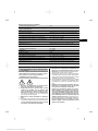
ORIGINAL OPERATING INSTRUCTIONS
PR 30‑HVS rotating laser
It is essential that the operating instructions
are read before the tool is operated for the
first time.
Always keep these operating instructions to-
gether with the tool.
Ensure that the operating instructions are
with the tool when it is given to other persons.
Contents Page
1 General information 2
2Description 2
3 Accessories 5
4 Technical data 5
5 Safety instructions 7
6Beforeuse 9
7 Operation 10
8 Care and maintenance 17
9 Troubleshooting 18
10 Disposal 19
11 Manufacturer’s warranty - tools 20
12 FCC statement (applicable in US) / IC
statement (applicable in Canada) 20
1 These numbers refer to the corresponding illustra-
tions. The illustrations can be found on the fold-out cover
pages. Keep these pages open while studying the oper-
ating instructions.
In these operating instructions, the designation “the tool”
or “the rotating laser” always refers to the PR 30-HVS.
“Remote control”, “laser receiver” or "receiver" always
refer to the PRA 30 (03).
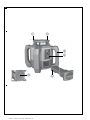
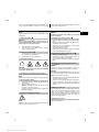
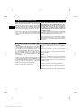
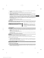
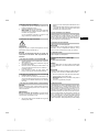
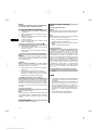
Rotating laser 1
@
Laser beam (plane of rotation)
;
Rotating head
=
Grip
%
Control panel
&
Base plate with ⁵/₈" thread
(
PRA 84 Li‑ion battery
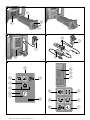
Inserting and removing the battery 2
@
PRA 84 Li‑ion battery
;
Battery compartment
=
Catch
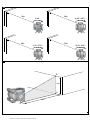
Charging the battery in the tool 3
@
PUA 81 AC adapter
;
Charging socket
Charging the battery after removal from the tool 4
@
PUA 81 AC adapter
;
PUA 82 motor vehicle power adapter
=
Charging activity LED
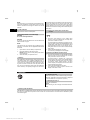
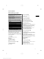
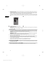
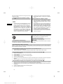
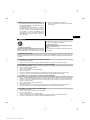
Rotating laser control panel 5
@
On/off button
;
Auto-leveling LED
=
LED arrow for electronic inclination alignment
%
Electronic inclination alignment button (only in con-
junction with inclined plane mode)
&
Shock warning function button and LED
(
Inclined plane mode button and LED
)
Surveillance mode LED (only with automatic vertical
alignment)
+
Battery charge status LED
PRA 30 control panel 6
@
On/off button
;
Inclination entry button (Plus / Right or Up arrow
button) (with the PRA 90)
=
Units button
%
Volume button
&
Inclination entry button (Minus / Left or Down arrow
button) (with the PRA 90:
(
Automatic alignment / surveillance mode button
(vertical) (double click)
)
Receiving window
+
Marking notch
§
Display
PRA 30 display 7
@
Display showing the position of the receiver relative
to the height of the laser plane
;
Battery status
=
Volume
%
Indication of distance from laser plane
en
1
Printed: 29.11.2013 | Doc-Nr: PUB / 5145249 / 000 / 01

/$6(55$',$7,21'2127
67$5(,172%($0
QP3R P:Ă530
&/$66,,/$6(5352'8&7
&$87,21
1 General information
1.1 Safety notices and their meaning
DANGER
Draws attention to imminent danger that will lead to
seriousbodilyinjuryorfatality.
WARNING
Draws attention to a potentially dangerous situation that
could lead to serious personal injury or fatality.
CAUTION
Draws attention to a potentially dangerous situation that
could lead to slight personal injury or damage to the
equipment or other property.
NOTE
Draws attention to an instruction or other useful informa-
tion.
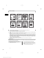
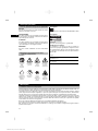
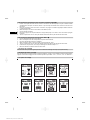
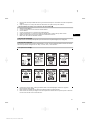
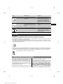
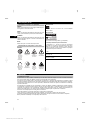
1.2 Explanation of the pictograms and other
information
Symbols
Read the
operating
instructions
before use.
General
warning
Warning:
caustic
substances
Warning:
electricity
For indoor
use only
Return waste
material for
recycling.
Do not look
into the
beam.
Warning:
explosive
substances
On the tool
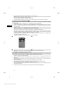
Laser Class 2 in accordance with IEC/EN 60825‑1:2007
On the tool
Laser Class II according to CFR 21, § 1040 (FDA)
Location of identification data on the tool
The type designation and serial number can be found on
thetypeidentificationplateonthetool.Makeanoteof
this data in your operating instructions and always refer
to it when making an enquiry to your Hilti representative
or service department.
Type:
Generation: 01
Serial no.:
2 Description
2.1 Use of the product as directed
The Hilti PR 30-HVS is a rotating laser tool with a visible rotating laser beam and a reference beam set at 90° to the
main beam. The rotating laser can be used vertically, horizontally and for inclined planes.
The tool is designed to be used to determine, transfer and check levels, verticals, slopes and right angles. Examples of
its uses are: transferring datums and height marks, determining right angles for walls, vertical alignment on reference
points and setting out slopes.
The tool is designed for professional use and may be operated, serviced and maintained only by trained, authorized
personnel. This personnel must be informed of any special hazards that may be encountered. The tool and its ancillary
equipment may present hazards when used incorrectly by untrained personnel or when used not as directed.
Hilti supplies various accessories which allow the tool to be used with maximum efficiency.
To avoid the risk of injury, use only genuine Hilti accessories and insert tools.
Observe the information printed in the operating instructions concerning operation, care and maintenance.
Take the influences of the surrounding area into account. Do not use the appliance where there is a risk of fire or
explosion.
Modification of the tool is not permissible.
en
2
Printed: 29.11.2013 | Doc-Nr: PUB / 5145249 / 000 / 01

2.2 Features
Thetoolmakesitpossibleforasinglepersontoleveloraligninanyplanequickly and with great accuracy.
The tool levels itself automatically after switching on. The laser beam is emitted only when the specified accuracy has
been achieved.
LEDs indicate the current operating status.
The tool is powered by a rechargeable Li‑ion battery which can be charged while the tool is in operation.
2.3 Combined use of the PRA 30 remote control / laser receiver
The PRA 30 is a combined remote control unit and laser receiver. It can be used to control the PR 30-HVS rotating
laser over great distances. The PRA 30 also serves as a laser receiver and can thus be used to detect and indicate the
laser beam at great distance.
2.4 Digital distance measurement display
The laser receiver displays digitally the distance between the laser plane and the marking notch. This allows the user to
determine the exact position of the receiver relative to the laser plane, with millimeter accuracy, in a single operation.
2.5 Automatic alignment and surveillance
Using the PR 30-HVS and the PRA 30, a person working alone can align the laser plane automatically with a certain
point with great accuracy. The tool detects the applicable alignment (horizontal, inclined or vertical) automatically and
uses the automatic alignment function accordingly (horizontal with the PRA 90 plus inclination) or automatic alignment
with subsequent monitoring of the plane (vertical). With the aid of the PRA 30, the surveillance function checks
alignment of the laser plane at regular intervals in order to avoid possible deviations due to temperature fluctuations,
wind or similar. The surveillance function can be deactivated.
2.6 Digital inclination display with patented electronic inclination alignment
The digital inclination display is capable of indicating an inclination of up to 21.3% when the PR 30-HVS is operating in
inclined mode. This makes it possible to set out and check slopes without having to make any calculations. Electronic
inclination alignment allows optimum inclination accuracy.
2.7 Shock warning
The shock warning function is activated two minutes after the tool has leveled itself after switching on. If a button
is pressed within these two minutes, the two-minute delay begins again. The tool switches to warning mode if it is
brought out of level while in operation (due to vibration or an impact); all LEDs begin to blink and the laser switches
off (the head stops rotating).
2.8 Automatic cut-out
The laser does not switch on and all LEDs blink if the tool is set up outside its self-leveling range (±5°) or if movement
is blocked mechanically.
The tool can be set up on a tripod with a 5/8" thread or stood directly on some other steady surface (free of vibration).
When automatic leveling is activated for one or both axes, the built-in servo system ensures that the specified accuracy
is maintained. The tool switches itself off when automatic leveling cannot be achieved (tool set up outside its leveling
range or physical impediment of the mechanism) or when knocked off level (see “Shock warning” section).
NOTE
If the correct level cannot be achieved, the laser switches itself off and all LEDs blink.
2.9 Items supplied
1 PR 30-HVS rotating laser
1 PRA 30 (03) laser receiver / remote control
1 PRA 80 or PRA 83 laser receiver holder
1 Operating instructions
1 PRA 84 Li‑ion battery
1PUA81ACadapter
2 Batteries (size AA cells)
en
3
Printed: 29.11.2013 | Doc-Nr: PUB / 5145249 / 000 / 01

2 Manufacturer’s certificates
1 Hilti toolbox
2.10 Operating status indicators
The tool is equipped with the following operating status indicators: Auto-leveling LED, battery charge status LED,
shock warning function deactivation LED, inclined plane mode LED, surveillance mode LED and electronic inclination
alignment LED.
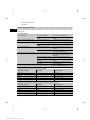
2.11 LED indicators
Auto-leveling LED The green LED blinks. The tool is in the leveling phase.
The green LED lights con-
stantly.
The tool has leveled itself / is operating
normally.
Shock warning deactivation LED The orange LED lights con-
stantly.
The shock warning function is deacti-
vated.
Inclined plane mode LED The orange LED blinks. Alignment in the sloping plane.
TheorangeLEDlightscon-
stantly.
Slope mode is active.
SurveillancemodeLED TheorangeLEDlightscon-
stantly.
The tool is in surveillance mode. Align-
ment with the reference point (PRA 30)
is correct.
The orange LED blinks. The tool is aligning the laser plane with
the reference point (PRA 30).
Electronic inclination alignment LED The orange LED arrows blink. The tool is in electronic inclination align-
ment mode, the PRA 30 receives no
laser beam.
Both orange LED arrows light
constantly.
The tool is correctly aligned with the
PRA 30.
The orange LED arrow on the
left lights
The tool must be rotated in a clockwise
direction.
The orange LED arrow on the
right lights
The tool must be rotated in a counter-
clockwise direction.
All LEDs All LEDs blink The tool has been bumped, knocked off
level or is exhibiting some error.
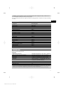
2.12 Charge status of the Li‑ion battery during operation
LEDs light constantly LEDs blink
Charge status C
LED1,2,3,4
-
C≧75%
LED1,2,3
-
50 % ≦ C < 75 %
LED 1, 2
-
25 % ≦ C < 50 %
LED 1
-
10 % ≦ C < 25 %
-
LED 1
C<10%
2.13 Charge status of the Li‑ion battery during charging while inserted in the tool
LEDs light constantly LEDs blink
Charge status C
LED1,2,3,4
-
C=100%
LED1,2,3 LED4
75 % ≦ C < 100 %
LED1,2 LED3
50 % ≦ C < 75 %
LED1 LED2
25 % ≦ C < 50 %
-
LED 1
C<25%
en
4
Printed: 29.11.2013 | Doc-Nr: PUB / 5145249 / 000 / 01

2.14 Battery charging activity is shown on the battery display while charging the battery outside the tool.
If the red LED lights constantly, the battery is being charged.
If the red charging activity LED does not light, then either the charging operation is complete or the charger is providing
no current.
3 Accessories
Designation
Short designation
Laser receiver / remote control PRA 30 (03)
Laser receiver PRA 20 (02)
Laser receiver holder PRA 80
Laser receiver holder PRA 83
Height transfer device PRA 81
Slope adapter PRA 79
AC adapter PUA 81
Car charging connector PUA 82
Battery PRA 84
Battery PRA 84G
Vertical angle PRA 770
Batter board adapter PRA 750
Batter board receiver holder PRA 751
Facade adapter PRA 760
Tripod PUA 20
Crank tripod (elevator tripod) PA 921
Crank tripod (elevator tripod) PUA 30
Automatic tripod PRA 90
Telescopic staffs PUA 50, PUA 55
4 Technical data
Right of technical changes reserved.
PR 30-HVS
Receiving range (diameter) With PRA 30 (03) (typical): 2…500 m (6.56…1,640.42 ft)
Range of remote control (circle diameter) With PRA 30 (03) (typical): 0…150m(0…492.13ft)
Accuracy
1
at 10 m: ± 0.75 mm
Plumb beam Continuous, perpendicular to the plane of rotation
Laser class Class 2, 620-690 nm; < 1 mW (EN 60825-1:2007 / IEC
60825-1:2007); Class II (CFR 21 § 1040 (FDA)); Maxi-
mum power < 4.85 mW at ≧ 300 r.p.m.
Speed of rotation 600/min, 1,000/min
Slope range
With the tool pre-inclined: ≤ 21.3%
Self-leveling range ±5°
1
Influences such as particularly high temperature fluctuations, dampness, shock, dropping, etc. can affect accuracy. Unless stated
otherwise, the tool was adjusted or calibrated under standard ambient conditions (MIL-STD-810G).
2
The drop test was carried out from a tripod, dropping onto flat concrete under standard ambient conditions (MIL-STD-810G).
en
5
Printed: 29.11.2013 | Doc-Nr: PUB / 5145249 / 000 / 01

Powersource 7.2V/4.5AhLi‑ionbattery
Battery life Temperature +25°C (+77 °F), Li‑ion battery: ≥ 25 h
Operating temperature range -20…+50°C (−4…+122 °F)
Storage temperature range (dry) -25…+60°C (−13…+140 °F)
Protection class IP 66 (in accordance with IEC 60529); Not in “charging
during operation” mode
Tripod thread ⁵⁄₈" x 18
Weight (incl. PRA 84) 2.5 kg (5.51 lb)
Dimensions (L x W x H) 200 mm (7.87") x 200 mm (7.87") x 230 mm (9.06")
Drop test height
2
1.5m(4.92ft)
1
Influences such as particularly high temperature fluctuations, dampness, shock, dropping, etc. can affect accuracy. Unless stated
otherwise, the tool was adjusted or calibrated under standard ambient conditions (MIL-STD-810G).
2
The drop test was carried out from a tripod, dropping onto flat concrete under standard ambient conditions (MIL-STD-810G).
PRA 30 (03)
Detection range (area diameter) Typical distance with PR 30-HVS: 2…500 m (6.56…
1,640.42 ft)
Signal tone generator 3 volume levels plus mute setting
Liquid-crystal display On both sides
Indicator range, distance from zero ± 52 mm
Laser plane display range ± 0.5 mm
Length of the detection area 120 mm (4.72")
Casing top edge center indicator 75 mm (2.95")
Marking notches On both sides
Time without detection before automatic power off 15 min
Dimensions (L × W × H) 160 mm (6.3") × 67 mm (2.64") × 24 mm (0.94")
Weight (including batteries) 0.25 kg (0.55 lb)
Power source 2 AA batteries
Battery life Temperature +20°C (+68 °F): Approx. 40 h (depending
on the quality of the alkaline batteries used)
Operating temperature range -20…+50°C (−4…+122 °F)
Storage temperature range -25…+60°C (−13…+140 °F)
Protection class IP 66 (in accordance with IEC 60529), except battery
compartment
Drop test height
1
2m(6.56ft)
1
The drop test was carried out using the PRA 83 receiver holder, dropped onto flat concrete under standard ambient conditions
(MIL-STD-810G).
PRA 84 Li‑ion battery
Rated voltage (normal mode) 7.2 V
Maximum voltage (during operation or during charging
while in operation)
13 V
Rated current 180 mA
Charging time
Temperature +32°C (+90 °F): 2 h 10 min (battery 80%
charged)
Operating temperature range -20…+50°C (−4…+122 °F)
Storage temperature range (dry) -25…+60°C (−13…+140 °F)
Charging temperature range (also for charging during
operation)
+0…+40°C (+32…+104 °F)
en
6
Printed: 29.11.2013 | Doc-Nr: PUB / 5145249 / 000 / 01

Weight 0.3 kg (0.66 lb)
Dimensions (L x W x H) 160 mm (6.3") x 45 mm (1.77") x 36 mm (1.42")
PUA 81 AC adapter
AC supply 115…230 V
AC frequency 47…63 Hz
Rated power 36 W
Rated voltage 12 V
Operating temperature range +0…+40°C (+32…+104 °F)
Storage temperature range (dry) -25…+60°C (−13…+140 °F)
Weight 0.23 kg (0.51 lb)
Dimensions (L x W x H) 110 mm (4.33") x 50 mm (1.97") x 32 mm (1.26")
5 Safety instructions
5.1 Basic information concerning safety
In addition to the information relevant to safety given
in each of the sections of these operating instructions,
the following points must be strictly observed at all
times.
5.2 General safety rules
a) Do not render safety devices ineffective and do
not remove information and warning notices.
b) Stay alert, watch what you are doing and use com-
mon sense when operating the machine. Don’t
use the machine when you are tired or under the
influence of drugs, alcohol or medication. Amo-
ment of inattention while operating machines may
result in serious personal injury.
c) Keep laser tools out of reach of children.
d) Failure to follow the correct procedures when open-
ing the tool may cause emission of laser radiation in
excess of class 2 or, respectively, class 3. Have the
tool repaired only at a Hilti service center.
e) Do not operate the tool in explosive atmospheres,
such as in the presence of flammable liquids,
gases or dust. Tools and appliances create sparks
which may ignite the dust or fumes.
f) (Statement in accordance with FCC §15.21):
Changes or modifications not expressly approved
by the manufacturer can void the user’s authority to
operate the equipment.
g) Use of setting-up / adjusting devices and equipment
or operating procedures other than those specified in
these instructions may lead to exposure to hazardous
radiation.
h) Check the condition of the tool before use. If the
tool is found to be damaged, have it repaired at a
Hilti service center.
i) Maintain the machine carefully. Check for mis-
alignment or binding of moving parts, breakage
of parts and any other condition that may affect
the machine’s operation. If damaged, have the
machine repaired before use. Poor maintenance is
the cause of many accidents.
j) The user must check the accuracy of the tool
after it has been dropped or subjected to other
mechanical stresses.
k) Check the tool before using it for important mea-
suring work.
l) Check the accuracy of the measurements several
times during use of the tool.
m) When the tool is brought into a warm environment
from very cold conditions, or vice-versa, allow it
to become acclimatized before use.
n) If mounting on an adapter, check that the tool is
screwed on securely.
o) Keep the laser exit aperture clean to avoid mea-
surement errors.
p) Although the tool is designed for the tough con-
ditions of jobsite use, as with other optical and
electronic instruments (e.g. binoculars, specta-
cles, cameras) it should be treated with care.
q) Although the tool is protected to prevent entry
of dampness, it should be wiped dry each time
before being put away in its transport container.
r) Keep the electrical contacts dry (protect from rain
or dampness).
s) Use the AC adapter only for connecting to the AC
supply.
t) Check to ensure that the tool and AC adapter do
not present an obstacle that could lead to a risk
of tripping and personal injury.
u) Ensure that the workplace is well lit.
v) Check the condition of the extension cord and
replace it if damage is found. Do not touch the AC
adapter if the extension cord or AC adapter are
damaged while working. Disconnect the supply
cord plug from the power outlet. Damaged supply
en
7
Printed: 29.11.2013 | Doc-Nr: PUB / 5145249 / 000 / 01

cords or extension cords present a risk of electric
shock.
w) Avoid body contact with earthed or grounded
surfaces such as pipes, radiators, ranges and
refrigerators. There is an increased risk of electric
shock if your body is earthed or grounded.
x) Do not expose the supply cord to heat, oil or sharp
edges.
y) Never operate the AC adapter when it is dirty or
wet. Dust (especially dust from conductive ma-
terials) or dampness adhering to the surface of
the AC adapter may, under unfavorable condi-
tions, lead to electric shock. Dirty or dusty tools
should thus be checked at a Hilti Service Center
at regular intervals, especially if used frequently
for working on conductive materials.
z) Avoid touching the contacts.
5.2.1 Battery tool use and care
a) Do not expose batteries to high temperatures or
fire. This presents a risk of explosion.
b) Do not disassemble, squash or incinerate bat-
teries and do not subject them to temperatures
over 80°C (176°F). A risk of fire, explosion or in-
jury through contact with caustic substances may
otherwise result.
c) Avoid ingress of moisture. Moisture in the interior
of the tool may cause a short circuit and chemical
reactions resulting in burns to the skin or fire.
d) Under abusive conditions, liquid may leak from the
battery. Avoid contact. If contact accidentally oc-
curs, flush with water. In the event of the liquid
coming into contact with the eyes, rinse the eyes
with plenty of water and consult a doctor. Liquid
ejected from the battery may cause irritation or burns.
e) Do not use batteries other than those approved
for use with the applicable tool or appliance. Use
of other batteries or use of the battery for purposes
for which it is not intended presents a risk of fire and
explosion.
f) Observe the special instructions applicable to the
transport, storage and use of Li-ion batteries.
g) When not in use, keep the battery and the charger
away from paper clips, coins, keys, nails, screws
or other small metal objects that could cause a
short circuit at the battery terminals or the charg-
ing contacts. A short circuit at the battery terminals
or charging contacts could result in personal injury
(burns) or fire.
h) Avoid short-circuiting the battery.Before inserting
the battery in the tool, check that the terminals of
the battery and the tool are free from foreign objects.
Short-circuiting the battery terminals presents a risk
of fire, explosion or contact with caustic substances.
i) Do not charge or continue to use damaged bat-
teries (e.g. batteries with cracks, broken parts,
bent or pushed-in and/or pulled-out contacts).
j) Use only the PUA 81 AC adapter, PUA 82 motor
vehicle power adapter or other chargers recom-
mended by the manufacturer to power the tool or
charge the battery. Failure to observe these points
may result in damage to the tool. Use of a charger
with batteries other than the specific type(s) for which
it is designed presents a risk of fire.
5.3 Proper organization of the work area
a) Secure the area in which you are working and
take care to avoid directing the beam towards
other persons or towards yourself when setting
up the tool.
b) Avoid unfavorable body positions when working
from ladders. Make sure you work from a safe
stance and stay in balance at all times.
c) Readings taken in the vicinity of reflective objects or
surfaces, through panes of glass or similar materials
may produce incorrect results.
d) Ensure that the tool is set up on a steady, level
surface (not subject to vibration).
e) Use the tool only within its specified limits.
f) Make sure that your PR 30-HVS is responding only
to your PRA 30 and not to other PRA 30s that may
be in use on the jobsite.
g) When working in “charging during operation”
mode, attach the mains adapter in a secure posi-
tion,e.g.onatripod.
h) When working in “charging during operation”
mode, attach the AC adapter in a secure posi-
tion,e.g.onatripod.
i) Use of products for applications different from those
intended could result in hazardous situations. Use
the product and its accessories etc. in accor-
dance with these instructions and in the manner
intended for the particular type of product. Take
the working conditions and the work to be per-
formed into account.
j) Use of the telescopic staff in the vicinity of over-
head high voltage cables is not permissible.
5.3.1 Electromagnetic compatibility
Although the tool complies with the strict requirements
of the applicable directives, Hilti cannot entirely rule out
the possibility of the tool being subject to interference
caused by powerful electromagnetic radiation, leading
to incorrect operation. Check the accuracy of the tool
by taking measurements by other means when working
under such conditions or if you are unsure. Likewise, Hilti
cannot rule out the possibility of interference with other
devices (e.g. aircraft navigation equipment).
5.3.2 Laser classification for Laser Class 2 / Class
II appliances
Depending on the version purchased, the tool com-
plies with Laser Class 2 in accordance with IEC825-
1:2007/EN60825-1:2007 and Class II in accordance with
CFR 21 § 1040 (FDA). This tool may be used without need
for further protective measures. The eyelid closure reflex
protects the eyes when a person looks into the beam un-
intentionally for a brief moment. This eyelid closure reflex,
en
8
Printed: 29.11.2013 | Doc-Nr: PUB / 5145249 / 000 / 01

however, may be negatively affected by medicines, alco-
hol or drugs. Nevertheless, as with the sun, one should
not look directly into sources of bright light. Do not direct
the laser beam toward persons.
6Beforeuse
NOTE
The tool may be powered only by a Hilti PRA 84 or PRA
84G battery.
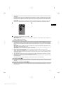
6.1 Fitting the battery 2
CAUTION
Before inserting the battery in the tool, check to
ensure that the battery terminals and the contacts in
the tool are free from foreign objects.
1. Slide the battery into the appliance.
2. Turn the catch in a clockwise direction until the
“locked” symbol appears.
6.2 Removing the battery 2
1. Turn the catch in a counter-clockwise direction until
the “unlocked” symbol appears.
2. Pull the battery out of the appliance.
6.3 Charging the battery
DANGER
Use only the Hilti batteries and Hilti mains adapters
listed under “Accessories”.
6.3.1 Charging a new battery for the first time
Charge the battery fully before using it for the first time.
NOTE
Make sure the system to be charged is standing securely.
6.3.2 Recharging a battery
1. Check that the outer surfaces of the battery are
clean and dry.
2. Insert the battery in the tool.
NOTE Li‑ion batteries are ready for use at any time,
even when only partly charged.
Charging progress is indicated by the LEDs when
the tool is switched on.
6.4 Options for charging the battery
NOTE
Make sure that the recommended temperature range is
observed when charging (0 to 40°C).
DANGER
The PUA 81 AC adapter is for indoor use only. Avoid
ingress of moisture.
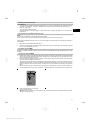
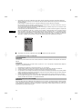
6.4.1 Charging the battery in the tool 3
1. Insert the battery in the battery compartment (see
6.1).
2. Rotate the socket cover until the charging socket on
the battery becomes visible.
3. Plug the cord from the AC adapter or motor vehicle
power adapter into the battery.
The battery will be charged.
4. Switch the tool on in order to display the charging
status while charging is in progress.
6.4.2 Charging the battery outside the tool 4
1. Remove the battery (see 6.2).
2. Connect the cord from the AC adapter or the motor
vehicle power adapter to the battery.
The red LED on the battery indicates charging ac-
tivity.
6.4.3 Charging the battery while the tool is in
operation
DANGER
Operation in “charging during operation” mode is not
permissible for outdoor use or in damp surroundings.
CAUTION
Avoid ingress of moisture. Moisture in the interior of
the tool may cause a short circuit and chemical reactions
resulting in burns to the skin or fire.
1. Rotate the socket cover until the charging socket on
the battery becomes visible.
2. Plug the cord from the AC adapter into the battery.
The tool continues to operate while charging and
battery charging status is indicated by the LEDs on
the tool.
6.5 Battery use and care
Store the battery in a cool, dry place. Never store the
battery where it is exposed to direct sunlight or sources
of heat, e.g. on heaters / radiators or behind a motor
vehicle windscreen. Batteries that have reached the end
of their life must be disposed of safely and correctly to
avoid environmental pollution.
6.6 Switching the tool on
Press the on/off button.
en
9
Printed: 29.11.2013 | Doc-Nr: PUB / 5145249 / 000 / 01

NOTE
After switching on, the tool begins to level itself automat-
ically. After completion of the leveling process, the laser
beam is switched on and begins to rotate in the normal
direction.
6.7 LED indicators
Please refer to section 2 “Description”.
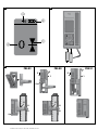
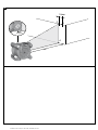
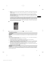
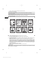
6.8 Inserting batteries in the PRA 30 8
DANGER
Do not use damaged batteries.
DANGER
Do not mix old and new batteries. Do not mix batteries of
different makes or types.
NOTE
The PRA 30 may be powered only by batteries manu-
factured in accordance with the applicable international
standards.
1. Open the laser receiver battery compartment.
2. Insert the batteries in the laser receiver.
NOTE Check to ensure correct polarity when insert-
ing the batteries.
3. Close the battery compartment cover.
6.9 Pairing
The rotating laser and the remote control / laser receiver
are already paired when supplied. Additional laser re-
ceivers of the same type or PRA 90 automatic tripods are
not ready for use until they have been paired. The rotat-
ing laser and these accessories must be paired before
they can be used together. Pairing tools and appliances
means that they are explicitly assigned to each other.
The rotating laser and the PRA 90 automatic tripod then
receive only signals from the remote control units / laser
receivers with which they have been paired. The pairing
enables appliances to work close to other rotating lasers
without the risk that their settings will be altered by these
other lasers.
6.9.1 Pairing the rotating laser and the laser
receiver
1. Press the on/off buttons on the rotating laser
and laser receiver simultaneously and keep them
pressed for at least 3 seconds.
Successful pairing is indicated by a signal tone emit-
ted by the laser receiver and all LEDs blinking on the
rotatinglaser.Atthesametime,the“Paired”symbol
appears briefly in the laser receiver display. The ro-
tating laser and the receiver switch off automatically
after pairing.
2. Switch the paired appliances on again.
The “Paired” symbol appears in the display.
6.9.2 Pairing the PRA 90 and the receiver
1. Press the on/off buttons on the PRA 90 automatic
tripod and laser receiver simultaneously and keep
them pressed for at least 3 seconds.
Successful pairing is indicated by a signal tone
emitted by the laser receiver and all LEDs blinking
on the PRA 90 automatic tripod. At the same time,
the “Paired” symbol appears briefly in the laser
receiver display. The tripod and the receiver switch
off automatically after pairing.
2. Switch the paired appliances on again.
The rotating laser with the tripod is shown in the
display on the laser receiver.
7Operation
7.1 Checking the tool
Check the accuracy of the tool before using it for impor-
tant tasks, especially if it has been dropped or subjected
to unusual influences or impacts etc. (see 8.6).
7.2 Switching the tool on
Press the on/off button.
NOTE
After switching on, the tool begins to level itself automat-
ically.
7.3 Working with the PRA 30
The PRA 30 is a combined laser receiver and remote control unit. The remote control makes working with the rotating
laser more convenient and is required in order to make use of certain functions. The laser beam is indicated by visual
and audible signals.
en
10
Printed: 29.11.2013 | Doc-Nr: PUB / 5145249 / 000 / 01

7.3.1 Working with the laser receiver as a hand-held unit
1. Press the on/off button.
2. Hold the laser receiver with the detection area directly in the plane of the rotating laser beam.
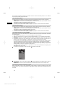
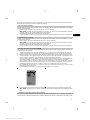
7.3.2 Working with the laser receiver in the PRA 80 receiver holder 9
1. Open the catch on the PRA 80.
2. Place the receiver in the PRA 80 receiver holder.
3. Close the catch on the PRA 80.
4. Switch the receiver on by pressing the on/off button.
5. Turn the rotating grip to the open position.
6. Secure the PRA 80 receiver holder on the telescopic staff or leveling staff by tightening the clamping knob.
7. Hold the laser receiver with the detection area directly in the plane of the rotating laser beam.
7.3.3 Working with the laser receiver in the PRA 83 receiver holder 9
1. Push the receiver into the rubber sleeve of the PRA 83 at an angle until it fully encloses the receiver. Take care to
ensure that the detection area and the buttons are facing the front.
2. Fit the receiver, complete with the rubber sleeve, onto the grip section. The cover and grip section are joined
together by the magnetic holder.
3. Switch the receiver on by pressing the on/off button.
4. Turn the rotating grip to the open position.
5. Secure the PRA 83 receiver holder on the telescopic staff or leveling staff by tightening the clamping knob.
6. Hold the laser receiver with the detection area directly in the plane of the rotating laser beam.
7.3.4 Working with the PRA 81 height transfer device 9
1. Open the catch on the PRA 81.
2. Insert the laser receiver in the PRA 81 height transfer device.
3. Close the catch on the PRA 81.
4. Switch the laser receiver on by pressing the on/off button.
5. Hold the laser receiver with the detection area directly in the plane of the rotating laser beam.
6. Position the laser receiver so that the distance display shows “0”.
7. Use the measuring tape to measure the desired distance.
7.3.5 Setting the measuring unit 6
The “Units” button can be used to set the desired accuracy of the digital display (mm/cm/off).
7.3.6 Volume adjustment 6
The laser receiver is set to “Normal” volume when switched on. The volume can be adjusted by pressing the “Volume”
button. One of four settings can be selected: “Low”, “Normal”, “High” or “Off”.
en
11
Printed: 29.11.2013 | Doc-Nr: PUB / 5145249 / 000 / 01

7.3.7 Menu options 6
1. Press and hold the on/off button for two seconds when switching the laser receiver on.
The menu then appears in the display.
2. Use the “Units” button to select metric or imperial measuring units.
3. Use the “Volume” button to assign the more rapid signal tone to the detection area above or below the marking
notch.
4. Use the arrow buttons (Left / Right) to select further points as necessary.
NOTE The arrow buttons (Left / Right) can be used to select settings. The “Units” button is used to change the
applicable settings. The following settings can be made: Display software version (no adjustment possible), PR
30-HVS sleep mode (off / on), units for inclined plane mode (%/°), pairing the PR 30-HVS (pair / separate), pairing
the PRA 90 (pair / separate), sensitivity of shock warning function (high / medium / low), wireless connection (on
/ off). Settings that affect the rotating laser only become effective when the rotating laser is switched on and a
wireless connection has been established.
5. To save the settings, switch the laser receiver off.
NOTE Each setting that has been made becomes effective the next time the tool is switched on.
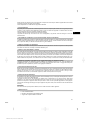
7.3.8 Double-click
When operating the tool, the “automatic alignment” and “surveillance” commandsmustbeconfirmedwithadouble-
click in order to avoid incorrect operation.
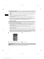
7.4 Deactivating the shock warning function
1. Switch the tool on (see 7.2).
2. Press the “Deactivate shock warning” button.
The shock warning deactivation LED lights con-
stantly, indicating that the function has been deac-
tivated.
3. To return to standard operating mode, switch the
tool off and then switch it back on again.
en
12
Printed: 29.11.2013 | Doc-Nr: PUB / 5145249 / 000 / 01

PP
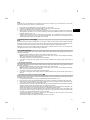
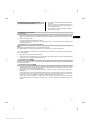
7.5 Working in the horizontal plane
7.5.1 Setting up
1. Set up the tool in a suitable position for the application, e.g. on a tripod. Alternatively, the rotating laser may be
mounted on a wall bracket. The angle of inclination of the surface on which it stands should not exceed ± 5°.
2. Press the on/off button.
The auto-leveling LED blinks green.
The laser switches on, the beam begins to rotate and the “auto leveling” LED lights as soon as the tool has
leveled itself.
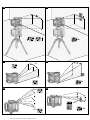
7.5.2 Alignment using the PRA 90 automatic tripod
NOTE
This function is available only with the PRA 90 automatic tripod.
When used for the first time, the PRA 30 laser receiver must be paired with thetripod(see6.9.2).
With the optional PRA 90 automatic tripod you can set the height of the laser plane to the desired level manually or
automatically.
1. Mount the tool on the PRA 90 automatic tripod.
2. Switch on the rotating laser, the automatic tripod and the laser receiver.Settheheightofthelaserplanemanually
(see 7.5.3) or automatically (see 7.5.4).
7.5.3 Manual alignment 6
Press the +/- buttons on the laser receiver or the arrow buttons on the PRA 90 to shift the horizontal plane up or down
(parallel).
7.5.4 Automatic alignment 6
1. Hold the laser receiver at the desired height with the detection area facing the PRA 90 control panel. Hold the
laser receiver still while alignment is taking place and take care to ensurethatthelineofsightbetweenthelaser
receiver and the tool is not obstructed.
2. Press the “Automatic alignment” button on the laser receiver twice in quick succession (double-click). Double-click
the button again to complete the procedure.
This double-click starts the process of bringing the laser plane into alignment, i.e. the tripod elevates or lowers
itself to the required height. A constant signal tone is emitted while this is taking place. As soon as the laser beam
strikes the detection area of the laser receiver, the beam moves to the position of the marking notch (reference
plane).
After the position has been reached and the rotating laser has leveled itself, a signal tone with a duration of 5
seconds indicates that the process is complete. The “Automatic alignment” symbol is then also no longer shown.
3. Check the height settings in the display.
4. Remove the laser receiver.
NOTE If the automatic alignment process was not successful, short signal tones are emitted and the “Automatic
alignment” symbol goes out.
en
13
Printed: 29.11.2013 | Doc-Nr: PUB / 5145249 / 000 / 01
A página está carregando...
A página está carregando...
A página está carregando...
A página está carregando...
A página está carregando...
A página está carregando...
A página está carregando...
A página está carregando...
A página está carregando...
A página está carregando...
A página está carregando...
A página está carregando...
A página está carregando...
A página está carregando...
A página está carregando...
A página está carregando...
A página está carregando...
A página está carregando...
A página está carregando...
A página está carregando...
A página está carregando...
A página está carregando...
A página está carregando...
A página está carregando...
A página está carregando...
A página está carregando...
A página está carregando...
A página está carregando...
A página está carregando...
A página está carregando...
A página está carregando...
A página está carregando...
A página está carregando...
A página está carregando...
A página está carregando...
A página está carregando...
A página está carregando...
A página está carregando...
A página está carregando...
A página está carregando...
A página está carregando...
A página está carregando...
A página está carregando...
A página está carregando...
A página está carregando...
A página está carregando...
A página está carregando...
A página está carregando...
A página está carregando...
A página está carregando...
A página está carregando...
A página está carregando...
A página está carregando...
A página está carregando...
A página está carregando...
A página está carregando...
A página está carregando...
A página está carregando...
A página está carregando...
A página está carregando...
A página está carregando...
A página está carregando...
A página está carregando...
A página está carregando...
A página está carregando...
A página está carregando...
A página está carregando...
A página está carregando...
A página está carregando...
A página está carregando...
A página está carregando...
-
 1
1
-
 2
2
-
 3
3
-
 4
4
-
 5
5
-
 6
6
-
 7
7
-
 8
8
-
 9
9
-
 10
10
-
 11
11
-
 12
12
-
 13
13
-
 14
14
-
 15
15
-
 16
16
-
 17
17
-
 18
18
-
 19
19
-
 20
20
-
 21
21
-
 22
22
-
 23
23
-
 24
24
-
 25
25
-
 26
26
-
 27
27
-
 28
28
-
 29
29
-
 30
30
-
 31
31
-
 32
32
-
 33
33
-
 34
34
-
 35
35
-
 36
36
-
 37
37
-
 38
38
-
 39
39
-
 40
40
-
 41
41
-
 42
42
-
 43
43
-
 44
44
-
 45
45
-
 46
46
-
 47
47
-
 48
48
-
 49
49
-
 50
50
-
 51
51
-
 52
52
-
 53
53
-
 54
54
-
 55
55
-
 56
56
-
 57
57
-
 58
58
-
 59
59
-
 60
60
-
 61
61
-
 62
62
-
 63
63
-
 64
64
-
 65
65
-
 66
66
-
 67
67
-
 68
68
-
 69
69
-
 70
70
-
 71
71
-
 72
72
-
 73
73
-
 74
74
-
 75
75
-
 76
76
-
 77
77
-
 78
78
-
 79
79
-
 80
80
-
 81
81
-
 82
82
-
 83
83
-
 84
84
-
 85
85
-
 86
86
-
 87
87
-
 88
88
-
 89
89
-
 90
90
-
 91
91


em outras línguas
- español: Hilti PRA 30-HVS Instrucciones de operación
- français: Hilti PRA 30-HVS Mode d'emploi
- English: Hilti PRA 30-HVS Operating instructions
Artigos relacionados
-
Hilti 3544727 Guia de usuario
-
-
-
-
Hilti PR 35 Instruções de operação
-
-
-
-
-