
E
PT
ES
F
www.DEWALT.com
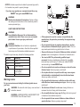
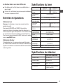
Self-Leveling Rotary Laser
DW080LRS, DW080LGS

8
Figures
2
A
B
C
10
11
12
13
14
15
16
17
18
19
1
2
6
7
4
3
5
7
6
4
3
2
5
1
8
9

3
3V CR2430
D
DEWALT 20V 2Ah
USB
F
E
5
7
6
6
8
DW0743GS
3
1
4
2
9
10
13
11
12
7
7
14

Figures
4
4
5
6
4
DW0743GS
5/8 - 11
1
2
3
G
H
1
2
5/8-11"
I
1
2
3
2

5
J
DW0743GS
< 50’
< 100’ < 1000’
< 100’
1
2
3

Figures
6
K
1
2

7
L

Figures
8
L
X
AA BB
M
L
X
A
B

9
L
Y
A
B
L
Y
AA BB
N

Figures
10
P
O

11
Q
2
1
4
3
5
6
7
8
4
2
3
1
8
9
S
R
T

12
E
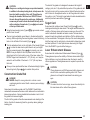
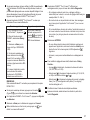
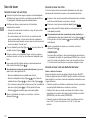
Contents
• Laser Information
• User Safety
• Batteries and Power
• Operating Tips
• Turning the Laser On
• Checking the Calibration
• Using the Laser
• Controlling the Laser Remotely
• Accessories
• Maintenance
• Troubleshooting
• Service and Repairs
• Specications
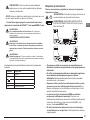
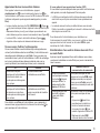
Laser Information
The DW080LRS/LGS Cordless Rotary Laser is a CLASS 3R laser
product and complies with 21 CFR 1040.10 and 1040.11 except for
deviations pursuant to laser notice No. 50, dated June 24, 2007.
Conforms to UL STDS 61010-1 & 2595
Certified to CSA STD C22.2 No. 61010-1
Complies with IEC 60825-1:2014
Supplier’s Declaration of Conformity
47 CFR § 2.1077 Compliance Information
Unique Identier: DW080LRS, DW080LGS
Responsible Party – U.S. Contact Information
D
EWALT
701 East Joppa Road
Towson, Maryland 21286
www.DEWALT.com
FCC Statement
These devices comply with Part 15 of the FCC Rules. Operation is
subject to the following two conditions: 1) this device may not cause
harmful interference, and 2) this device must accept any interference
received, including interference that may cause undesired operation.
NOTE: This equipment has been tested and found to comply with
the limits for a Class B digital device, pursuant to Part 15 of the FCC
Rules. These limits are designed to provide reasonable protection
against harmful interference in a residential installation. This
equipment generates, uses and can radiate radio frequency energy
and, if not installed and used in accordance with the instructions,
may cause harmful interference to radio communications. However,
there is no guarantee that interference will not occur in a particular
installation. If this equipment does cause harmful interference to
radio and television reception, which can be determined by turning
the equipment off and on, the user is encouraged to try to correct the
interference by one or more of the following measures:
• Reorient or relocate the receiving antenna.
• Increase the separation between the equipment and receiver.
• Connect the equipment into an outlet on a circuit differentfrom that
which the receiver is connected.
• Consult the dealer or an experienced radio/TV technician for help.
Canada, Industry Canada (IC) Notices
Class B digital circuitry of this device complies with Canadian ICES-
003. This device complies with Industry Canada license-exempt RSS
standard(s). Operation is subject to the following two conditions:
1) this device may not cause interference, and 2) this device must
accept any interference, including interference that may cause
undesired operation of the device.
READ ALL INSTRUCTIONS
User Safety
Safety Guidelines
The denitions below describe the level of severity for each signal
word. Please read the manual and pay attention to these symbols.
DANGER: Indicates an imminently hazardous situation
which, if not avoided, will result in death or serious injury.
WARNING: Indicates a potentially hazardous situation
which, if not avoided, could result in death or serious injury.
CAUTION: Indicates a potentially hazardous situation
which, if not avoided, may result in minor or moderate injury.

13
E
NOTICE: Indicates a practice not related to personal injury which,
if not avoided, may result in property damage.
If you have any questions or comments about this or any
D
EWALT
®
tool, go to www.DEWALT.com.
WARNING:
Read and understand all instructions. Failure to follow
the warnings and instructions in this manual may result in
serious personal injury.
SAVE THESE INSTRUCTIONS
WARNING:
Laser Radiation Exposure. Do not disassemble or
modify the laser level. There are no user serviceable
parts inside. Serious eye injury could result.
WARNING:
Hazardous Radiation. Use of controls or adjustments,
or performance of procedures, other than those specied
herein may result in hazardous radiation exposure.
The label on your laser may include the following symbols.
Symbol Meaning
V Volts
mW Milliwatts
Laser Warning
nm Wavelength in
nanometers
3R Class 3R Laser
Warning Labels
For your convenience and safety, the following labels are on
your laser.
WARNING: To reduce the risk of injury, user must read
instruction manual.
WARNING: LASER RADIATION. AVOID DIRECT EYE
EXPOSURE. Class 3R Laser Product.
• If the equipment is used in a manner not specied by the
manufacturer, the protection provided by the equipment may
be impaired.
• Do not operate the laser in explosive atmospheres, such as
in the presence of ammable liquids, gases, or dust. This tool
may create sparks which may ignite the dust or fumes.
• Store an idle laser out of reach of children and other untrained
persons. Lasers are dangerous in the hands of untrained users.
• Tool service MUST be performed by qualied repair
personnel. Service or maintenance performed by unqualied
personnel may result in injury. To locate your nearest D
EWALT
service center go to www.DEWALT.com.
• Do not use optical tools such as a telescope or transit to view
the laser beam. Serious eye injury could result.
• Do not place the laser in a position which may cause anyone
to intentionally or unintentionally stare into the laser beam.
Serious eye injury could result.
• Do not position the laser near a reective surface which may
reect the laser beam toward anyone’s eyes. Serious eye injury
could result.
• Turn the laser off when it is not in use. Leaving the laser on
increases the risk of staring into the laser beam.
• Do not modify the laser in any way. Modifying the tool may result
in hazardous laser radiation exposure.
• Do not operate the laser around children or allow children to
operate the laser. Serious eye injury may result.

14
E
• Do not remove or deface warning labels. If labels are removed,
the user or others may inadvertently expose themselves to
radiation.
• Position the laser securely on a level surface. If the laser falls,
damage to the laser or serious injury could result.
Personal Safety
• Stay alert, watch what you are doing, and use common sense
when operating a laser product. Do not use the tool while
tired or under the influence of drugs, alcohol, or medication.
A moment of inattention while operating laser products may result
in serious personal injury.
• Use appropriate personal protective equipment, including eye
protection when working in a construction environment.
Tool Use and Care
• Do not use the tool if the switch does not turn it on or off. Any
tool that cannot be controlled with the switch is dangerous and
must be repaired.
• Store idle laser products out of the reach of children and do
not allow persons unfamiliar with the laser product or these
instructions to operate the laser product. Laser products are
dangerous in the hands of untrained users.
• Use only accessories that are recommended by the
manufacturer for your model. Accessories that may be suitable
for one tool, may become hazardous when used with another tool.
Batteries and Power
This DeWALT rotary laser will accept all DeWALT 20 volt lithium ion
battery packs, but is built to best resist damage during a fall when
used with the following batteries: All 1.5Ah and 2Ah DeWALT 20 volt
lithium ion battery packs.
Charging the Battery Pack
The battery pack is not fully charged out of the carton. You need to
use a DeWALT 20 volt charger to charge the battery pack before you
can use the rotary laser.
• Be sure to read all safety instructions before using your charger.
WARNING:
DO NOT attempt to charge the battery pack with any
chargers other than the ones listed in this manual. The
charger and battery pack are specifically designed to work
together.
WARNING:
Carefully follow all instructions and warnings on the battery
label and package and accompanying Battery Safety
Manual.
1.
Slide the battery pack into the charger as described in the
Battery Safety Manual.
2.
Wait until the battery pack is fully charged.
3.
Slide the battery pack out of the charger.
NOTE: When ordering replacement battery packs, be sure to include
the catalog number and voltage.
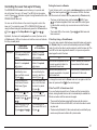
Installing the DeWALT 20V Battery Pack
1.
Position the fully-charged DEWALT 20V battery pack so the
release button (Figure
D
1
) is facing away from you and to the
right.
2.
Press and hold down the release button (Figure
D
1
) on the
battery pack.
3.
Slide the battery pack all the way into the track on the side of
the laser (Figure
D
2
).
4.
Release the button on the battery pack.
Removing the Battery Pack
1.
Press and hold the release button on the battery pack (Figure
D
1
).
2.
Slide the battery pack out of the track on the laser.
3.
Release the button on the battery pack.
4.
To recharge the battery pack, insert it into the charger, as
described in the Battery Safety Manual.

15
E
WARNING:
Batteries can explode or leak, and can cause injury or fire.
To reduce this risk, follow the instructions in the Battery
Safety Manual.
Storing Battery Packs
• The best storage place is one that is cool and dry, and away from
direct sunlight and excess heat or cold.
• Long storage will not harm the battery pack or charger. Under
proper conditions, they can be stored for 5 years or more.
SAVE THESE INSTRUCTIONS FOR FUTURE USE
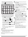
Installing the Coin Cell Battery
A coin cell battery should already be installed in the bottom of
the laser unit (Figure
D
3
) so it is ready to use the Bluetooth
®
connection, after you remove the battery protector. To remove the
battery protector on your new laser, or replace the coin cell battery in
the future, follow these steps.
1.
Carefully turn the laser upside down.
2.
On the bottom of the laser, unscrew the battery compartment cover,
which is marked 3V CR2430.
3.
Lift off the battery compartment cover and remove the coin cell
battery.
4.
If your laser is new, remove the battery protector (round disc), and
then re-insert the same coin cell battery.
5.
If your laser is not new, insert a new 3V CR2430 coin cell battery into
the battery compartment.
6.
Carefully place the battery compartment cover back in the correct
position and use the screws to secure the cover in place on the
bottom of the laser unit.
THE BLUETOOTH
®
WORD MARK AND LOGOS ARE REGISTERED TRADEMARKS OWNED
BY BLUETOOTH SIG, INC. AND ANY USE OF SUCH MARKS BY DEWALT IS UNDER LI-
CENSE. APPLE AND THE APPLE LOGO ARE TRADEMARKS OF APPLE INC., REGISTERED
IN THE U.S. AND OTHER COUNTRIES. APP STORE IS A SERVICE MARK OF APPLE INC.,
REGISTERED IN THE U.S. AND OTHER COUNTRIES. GOOGLE PLAY AND THE GOOGLE
PLAY LOGO ARE TRADEMARKS OF GOOGLE INC.
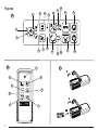
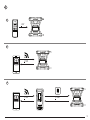
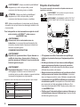
Installing Batteries in the Remote
Load new AAA batteries into the remote so you can use it with the
laser unit.
1.
On the bottom of the remote, lift up the latch to open the battery
compartment cover (Figure
C
1
).
2.
Insert two new, high-quality, name brand AAA batteries, making
sure to position the - and + ends of each battery as noted inside the
battery compartment (Figure
C
2
).
3.
Push the battery compartment cover closed until it snaps into
place (Figure
C
3
).
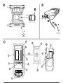
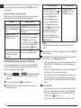
Charging the Detector
The Digital Laser Detector is powered by a Li-ion battery. To charge
the battery.
1.
Insert the USB end of the charging cable into a USB port (Figure
E
1
).
2.
On the Detector, pull the Micro USB port cover (Figure
E
2
) off
and to the side.
3.
Insert the Micro USB end of the charging cable into the
Detector’s Micro USB port (Figure
E
3
).
4.
Allow the Detector time to fully-charge. The LED on the Detector
will remain Red as the battery is charging (Figure
F
13
).
5.
When the LED on the Detector turns Green, remove the
charging cable.
The RBRC® Seal
The RBRC® (Rechargeable Battery Recycling
Corporation) Seal on the nickel cadmium, nickel metal
hydride or lithium-ion batteries (or battery packs)
indicates that the costs to recycle these batteries (or
battery packs) at the end of their useful life have already
been paid by
DeWALT. In some areas, it is illegal to
place spent nickel cadmium, nickel metal hydride
or lithium-ion batteries in the trash or municipal solid waste stream and the
Call 2 Recycle® program provides an environmentally conscious alternative.

16
E
Call 2 Recycle, Inc., in cooperation with DeWALT and other battery users,
has established the program in the United States and Canada to facilitate the
collection of spent nickel cadmium, nickel metal hydride or lithium-ion batteries.
Help protect our environment and conserve natural resources by returning
the spent nickel cadmium, nickel metal hydride or lithium-ion batteries to an
authorized
DeWALT service center or to your local retailer for recycling. You may
also contact your local recycling center for information on where to drop off the
spent battery. RBRC® is a registered trademark of Call 2 Recycle, Inc.
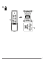
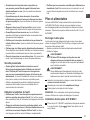
Operating Tips
• To extend battery life per charge, turn the laser off when it is not
in use.
• To ensure the accuracy of your work, check the laser calibration
often. Refer to Checking the Calibration.
• Before attempting to use the laser, make sure the tool is
positioned on a relatively smooth, secure surface.
• Always mark the center of the laser line or dot. If you mark
different parts of the beam at different times you will introduce
error into your measurements.
• To increase working distance and accuracy, set up the laser in the
middle of your working area.
• When attaching to a tripod or wall, mount the laser securely.
• When working indoors, a slow rotary head speed will produce
a visibly brighter line, a faster rotary head speed will produce a
visibly solid line.
• To increase beam visibility, wear Laser Enhancement Glass es
(Figure
T
) and/or use a Laser Target Card (Figure
S
) to help find
the beam.
• Extreme temperature changes can cause movement or shifting
of building structures, metal tripods, equipment, etc., which can
effect accuracy. Check your accuracy often while working.
• If the laser is dropped or has suffered a sharp blow, have the
calibration system checked by a qualified service center before
using the laser.
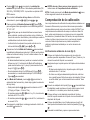
Turning the Laser On
1.
Insert the fully charged DEWALT 20V battery pack as shown in
Figure
D
.
2.
Gently press the power button to power ON the laser:
• The power LED indicator light (Figure
A
3
) will illuminate.
• Self-leveling mode is activated automatically and the laser unit
will self-level. Once the laser unit is level, the beam will rotate
clockwise once at 600RPM.
• 30 sec. after the last button press, HI Mode (Height of
Instument, Anti-Drift) is activated automatically and the HI LED
(Figure
A
2
) will illuminate. (You can disable HI Mode by
holding down the Slope Mode button for 2 secs. The laser
will beep twice and the HI Mode LED will turn off. NOTE: when
HI Mode is disabled, the laser cannot detect any movement
after setup, so accuracy cannot be guaranteed.)
3.
Press (Figure
A
16
) to adjust the Rotation Speed of the
laser beam through its 4 preset speeds (150, 300, 600, and
1200 RPM). NOTE: Accuracy is best optimized at 600 RPM or
less.
4.
To change the Direction of the laser beam while in self-leveling
mode, press or (Figure
A
18
or
19
).
5.
Press the Scan Mode button
15˚/45˚/90˚
(Figure
A
17
) to set the laser
to scan in 0°, 15°, 45°, or 90° angle mode.
•
15˚/45˚/90˚
is used to make the laser head sweep back and forth,
creating a short, bright laser line. This short line is much
brighter and more visible than when the unit is in full rotation
mode.
• The direction of the scan zone can be controlled with the arrow
buttons
and (Figure
A
18
or
19
)
6.
If you press the Slope Mode button to turn ON Slope Mode,
the unit automatically engages the X-Axis. This allows you to
slope the laser in the direction of the X-Axis, as indicated by the
X mark on the top roll cage.
• In certain situations, it may be desirable to slope the laser in
the Y-axis. The direction of Slope Mode can be changed back
and forth between the Y-axis and the X-axis by pressing the
X-Y axis button
(Figure
A
13
).

17
E
• If using X-axis slope, the X-axis LED (Figure
A
15
) will light,
or if using Y-axis slope, the Y-axis LED (Figure
A
14
) will light
instead.
7.
When in Slope Mode, press or to tilt the laser head up and
down (adjust the elevation of the laser beam).
• Each quick press of
or will move the slope by 0.01º (1/16”
@ 30ft. or 1.6mm @ 10m).
• If you press and hold
or between 2 sec - 10 sec, the
slope will move from 0.01º/sec to 0.2º/sec.
• If you press and hold
or longer than 10 sec, the slope
will move 0.2º/sec.
8.
To turn off the laser unit, press and hold the power button for 3
secs.
9.
BEFORE using the laser for your first project, follow the
instructions for Checking the Calibration.
NOTE: When you press the Slope Mode button
again, the laser
will return to self-level mode.
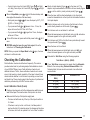
Checking the Calibration
Field calibration checks should be done frequently. This section
provides instructions for performing simple field calibration checks
of your DeWALT Rotary Laser. Field calibration checks do not
calibrate the laser. That is, these calibration checks do not correct
errors in the leveling or plumb capability of the laser. Instead, these
checks indicate whether or not the laser is providing a correct level
and plumb line. These checks cannot take the place of professional
calibration performed by a
DeWALT service center.
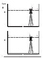
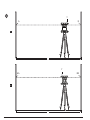
Level Calibration Check (X-axis)
1.
Position a tripod securely on the floor between two walls that are at
least 50 feet apart. The exact location of the tripod is not critical.
2.
Make sure that the top of the tripod is roughly level.
• The laser will self-level only if the top of the tripod is within ±
5˚ of level.
• If the laser is set up too far out of level, it will beep when it
reaches the limit of its leveling range. No damage will be done
to the laser, but it will not operate in an “out of level” condition.
3.
Attach a tripod adapter (Figure
G
1
) to the laser unit. The
adapter may be assembled to the bottom for level mode (Figure
G
2
) or to the side for plumb (vertical) mode (Figure
I
3
).
4.
Place the laser with the attached adapter on the tripod and
screw the threaded knob on the tripod into the female thread on
the tripod adapter.
5.
Position the laser unit on the tripod so that the laser’s X-axis
points directly toward one of the walls (Figure
M
1
).
6.
Turn the laser unit on and allow it to self-level.
7.
Where the beam appears on the left wall, mark point A, and where
the beam appears on the right wall mark point B.
8.
Turn the laser unit 180º so that the X-axis points directly toward
the opposite wall (Figure
M
2
).
9.
Allow the laser unit to self-level.
10.
Where the beam appears on the left wall, mark point AA, and
where the beam appears on the right wall mark point BB.
11.
Calculate the Total Error using the following equation:
Total Error = (AA-A) - (BB-B)
12.
If your Total Error measurement is greater than the Allowable
Error for the corresponding Distance Between Walls in the
following table, the laser must be serviced at an authorized
service center.
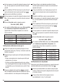
L (Distance Between
Walls)
Allowable Error
40′ (15m) 3/64” (1.5mm)
50′ (20m) 1/16” (2mm)
70′ (25m) 3/32” (2.5mm)
100’ (30m)
1/8” (3mm)

18
E
Level Calibration Check (Y-axis)
1.
Set up a tripod between two walls that are at least 50 feet apart. The
exact location of the tripod is not critical.
2.
Make sure that the top of the tripod is roughly level.
• The laser will self-level only if the top of the tripod is within ±
5˚ of level.
• If the laser is set up too far out of level, it will beep when it
reaches the limit of its leveling range. No damage will be done
to the laser, but it will not operate in an “out of level” condition.
3.
Attach a tripod adapter (Figure
G
1
) to the laser unit. The
adapter may be assembled to the bottom for level mode (Figure
G
2
) or to the side for plumb (vertical) mode (Figure
I
3
).
4.
Place the laser with the attached adapter on the tripod and
screw the threaded knob on the tripod into the female thread on
the tripod adapter.
5.
Position the laser unit on the tripod so that the laser’s Y-axis
points directly toward one of the walls (Figure
N
1
).
6.
Turn the laser unit on and allow it to self-level.
7.
Where the beam appears on the left wall, mark point A, and where
the beam appears on the right wall mark point B.
8.
Turn the laser unit 180º so that the Y-axis points directly toward
the opposite wall (Figure
N
2
).
9.
Allow the laser unit to self-level.
10.
Where the beam appears on the left wall, mark point AA, and
where the beam appears on the right wall mark point BB.
11.
Calculate the Total Error using the following equation:
Total Error = (AA-A) - (BB-B)
12.
If your Total Error measurement is greater than the Allowable
Error for the corresponding Distance Between Walls in the
following table, the laser must be serviced at an authorized
service center.
L (Distance Between Walls) Allowable Error
40′ (15m) 3/64” (1.5mm)
50′ (20m) 1/16” (2mm)
70′ (25m) 3/32” (2.5mm)
100′ (30m) 1/8” (3mm)
Plumb Error Check
Perform this check using a wall that is no shorter than the tallest wall
for which this rotary laser will be used (Figure
O
).
1.
Using a standard plumb bob as a reference, mark the top and
bottom of a wall. (Be sure to mark the wall and not the oor or
ceiling).
2.
Position the rotary laser securely on the oor approximately 3”
(1m) from the wall.
3.
Turn the laser on and point the laser dot at the mark on the
bottom of the wall.
4.
Using the or arrow on the Remote Control (Figure
B
6
or
B
7
), rotate the dot upwards.
5.
If the center of the dot scans over the mark on the top of the
wall, the laser is properly calibrated.
Using the Laser
Using the Laser on a Tripod
1.
Position a tripod securely and set it to the desired height. Make
sure that the tripod has a 5/8”-11 threaded screw to ensure
secure mounting of the laser unit.
2.
Make sure that the top of the tripod is roughly level.
• The laser will self-level only if the top of the tripod is within ±
5˚ of level.
• If the laser is set up too far out of level, it will beep when it
reaches the limit of its leveling range. No damage will be done
to the laser, but it will not operate in an “out of level” condition.

19
E
3.
Attach a tripod adapter (Figure
G
1
) to the bottom of the laser
unit (Figure
G
2
).
4.
Place the laser with the attached adapter on the tripod and
screw the threaded knob on the tripod into the female thread on
the tripod adapter.
5.
Turn the laser ON and allow it to self-level in horizontal (level)
mode (Figure
H
1
).
6.
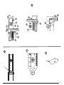
If you want to use the laser in vertical (plumb) mode, follow
these steps while the laser is still ON:
• Carefully remove the laser unit from the tripod.
• Remove the tripod adapter (Figure
I
1
) from the bottom of
the laser unit (Figure
I
2
) and attach it to the side (Figure
I
3
).
• With the laser in the vertical (plumb) position, attach the laser
unit to the tripod (Figure
I
4
). The Dot rotates down to 6
o’clock.
• Press
to make sure the laser rotates.
7.
Adjust the rotation speed and controls, as desired (Figure
P
).
Using the Laser on a Floor
The laser level can be positioned directly on the floor for leveling and
plumbing applications such as framing walls.
1.
Place the laser on a relatively smooth and level surface where it
will not be disturbed or exposed to vibration.
2.
Position the laser for a level setting (Figure
H
1
).
3.
Turn the laser ON and allow it to self-level in level (horizontal)
mode.
4.
If you want to use the laser in plumb (vertical) mode,
carefully turn the laser so the keypad is at the top (Figure
H
2
). The Dot rotates down to 6 o’clock. Press to make
sure the laser rotates.
5.
Adjust the rotation speed and controls, as desired (Figure
P
).
NOTE:
The laser will be easier to set up for wall applications if the
rotation speed is set to 0 RPMs and the remote control is used
to line up the laser with control marks. The remote allows one
person to set up the laser.
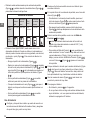
Using the Laser With a Laser Detector
How the Detector works
Some laser kits include a
DeWALT Digital Laser Detector. The
DeWALT Digital Laser Detector allows you to locate a laser beam
emitted by a rotary laser in bright light conditions or over long
distances.
• The detector can be used in both indoor and outdoor situations
where it is difficult to see the laser beam.
• The detector is not for use with non-rotating lasers but is
compatible with most rotary red-beam (DW080LRS) and green
beam (DW080LGS) lasers.
• The detector can be set to indicate the location of the beam to
either the nearest 5/64” (2 mm) or the nearest 3/64” (1 mm).
• The detector gives both visual signals through the display window
(Figure
F
6
) and audio signals through the speaker (Figure
F
5
)
to indicate the location of the laser beam.
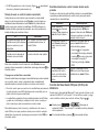
Detector’s Indicators
Above
Grade
Slightly
Above
Grade
On
Grade
Slightly
Below
Grade
Below
Grade
Audible
Signal
Fast
Beep
Fast
Beep
Steady
Tone
Slow
Beep
Slow
Beep
Display
Icon

20
E
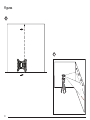
• The DEWALT Digital Laser Detector can be used with or without
the detector clamp. When used with the clamp, the detector can be
positioned on a grade rod, leveling pole, stud, or post (Figure
G
).
To connect the detector to the clamp:
• Push in the clamp latch (Figure
G
3
).
• Slide the tracks on the clamp (Figure
G
4
) around the rail on
the back of the detector (Figure
F
11
) until the button (Figure
G
5
) on the clamp snaps into the latch hole on the back of the
detector (Figure
F
12
).
• Turn the clamp knob (Figure
G
6
) counterclockwise to open the
jaws on the clamp.
• Place the clamp on the rod (Figure
G
2
) so that the detector is
positioned at the height needed to work with the laser.
• Turn the clamp knob (Figure
G
6
) clockwise to secure the clamp
on the rod.
Using the Detector
1.
Set up and position the rotary laser that you will be using
according to the manufacturer’s directions. Turn the laser on and
make sure the laser is rotating and emitting a laser beam.
2.
Press the power button once on the detector to turn the detector
on.
3.
On the bottom of the display window, notice the speaker icon
(Figure
F
10
).
• To decrease the volume of the audible signal, press the volume
button (Figure
F
4
); both half circles next to the speaker icon
(Figure
F
10
)will dissappear.
• To turn off the audible signal, press the volume button (Figure
F
4
) until the speaker icon dissapears from the display
window.
4.
On the top of the display window, view the Accuracy Mode icon
(Figure
F
8
).
•
indicates that the detector will give an “on grade” reading
only when the laser beam is on grade or no more than 1/25” (1
mm) above or below it.
• To change the Accuracy Mode to
to have the detector
give an “on grade” reading when the laser beam is on grade
or approximately 1/8” (3 mm) above or below it, press the
Accuracy Mode button (Figure
F
3
) once. Then (Figure
F
9
) appears on the display window.
5.
Position the detector so that the Beam Detection window (Figure
F
14
) is facing the laser beam produced by the rotary laser
(Figure
G
). Move the detector up or down within the
approximate area of the beam, until you have centered the
detector.
6.
Use the marking notches (Figure
F
7
) to accurately mark the
position of the laser beam.
7.
To turn the detector off.
• On the detector, press
for 3 seconds.
• If a rotary laser beam does not strike the detector’s beam
detection window, or if no detector buttons are pressed, within
30 minutes, the detector will shut itself off.
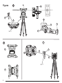
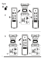
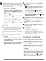
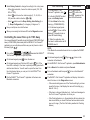
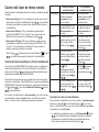
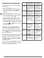
Controlling the Laser Remotely
You can control the laser unit remotely in either of these 3 ways:
• From up to 50’ away, you can use the remote to control the
laser unit (Figure
J
1
). IR sensors will maintain communication
between the remote and the laser unit.
• From up to 100’ away, you can use the D
EWALT
®
Tool Connect™
Application on your Bluetooth
®
device to connect to the laser unit
(Figure
J
2
).
• From up to 1100’ away, you can control the laser unit by using the
DEWALT
®
Tool Connect™ Application on your Bluetooth
®
device to
connect to the detector that is connected to the laser unit (Figure
J
3
). You must press the Detector button (Figure
A
6
) on
the laser in order to connect the detector to the laser unit.
A página está carregando...
A página está carregando...
A página está carregando...
A página está carregando...
A página está carregando...
A página está carregando...
A página está carregando...
A página está carregando...
A página está carregando...
A página está carregando...
A página está carregando...
A página está carregando...
A página está carregando...
A página está carregando...
A página está carregando...
A página está carregando...
A página está carregando...
A página está carregando...
A página está carregando...
A página está carregando...
A página está carregando...
A página está carregando...
A página está carregando...
A página está carregando...
A página está carregando...
A página está carregando...
A página está carregando...
A página está carregando...
A página está carregando...
A página está carregando...
A página está carregando...
A página está carregando...
A página está carregando...
A página está carregando...
A página está carregando...
A página está carregando...
A página está carregando...
A página está carregando...
A página está carregando...
A página está carregando...
A página está carregando...
A página está carregando...
A página está carregando...
A página está carregando...
A página está carregando...
A página está carregando...
A página está carregando...
A página está carregando...
A página está carregando...
A página está carregando...
A página está carregando...
A página está carregando...
A página está carregando...
A página está carregando...
A página está carregando...
A página está carregando...
A página está carregando...
A página está carregando...
A página está carregando...
A página está carregando...
A página está carregando...
A página está carregando...
-
 1
1
-
 2
2
-
 3
3
-
 4
4
-
 5
5
-
 6
6
-
 7
7
-
 8
8
-
 9
9
-
 10
10
-
 11
11
-
 12
12
-
 13
13
-
 14
14
-
 15
15
-
 16
16
-
 17
17
-
 18
18
-
 19
19
-
 20
20
-
 21
21
-
 22
22
-
 23
23
-
 24
24
-
 25
25
-
 26
26
-
 27
27
-
 28
28
-
 29
29
-
 30
30
-
 31
31
-
 32
32
-
 33
33
-
 34
34
-
 35
35
-
 36
36
-
 37
37
-
 38
38
-
 39
39
-
 40
40
-
 41
41
-
 42
42
-
 43
43
-
 44
44
-
 45
45
-
 46
46
-
 47
47
-
 48
48
-
 49
49
-
 50
50
-
 51
51
-
 52
52
-
 53
53
-
 54
54
-
 55
55
-
 56
56
-
 57
57
-
 58
58
-
 59
59
-
 60
60
-
 61
61
-
 62
62
-
 63
63
-
 64
64
-
 65
65
-
 66
66
-
 67
67
-
 68
68
-
 69
69
-
 70
70
-
 71
71
-
 72
72
-
 73
73
-
 74
74
-
 75
75
-
 76
76
-
 77
77
-
 78
78
-
 79
79
-
 80
80
-
 81
81
-
 82
82


DeWalt DW080LRS Manual do usuário
- Tipo
- Manual do usuário
- Este manual também é adequado para
em outras línguas
- español: DeWalt DW080LRS Manual de usuario
- français: DeWalt DW080LRS Manuel utilisateur
- English: DeWalt DW080LRS User manual
Artigos relacionados
-
DeWalt DW079LGDW0881 Manual do usuário
-
-
DeWalt DCE080D1GS Manual do usuário
-
DeWalt DCLE34220 12V/20V 2-Dot Cross Line Laser Manual do usuário
-
-
DeWalt DCE074D1R Manual do usuário
-
-
-
-
Outros documentos
-
Sony PHA-1A Manual do proprietário
-
Makita SKR301 Manual do proprietário
-
CST/Berger LM30 Manual do usuário
-
Stanley RLHGW Manual do usuário
-
RIDGID micro CL-100 Manual do usuário
-
-
Sokkia iM-50 Series Total Station Manual do usuário
-
Stanley RL350GL Manual do usuário
-
-
Craftsman CMXELAYMPL1031 Manual do usuário