Ingersoll Rand Air Compressor EP50-PE Manual do usuário
- Categoria
- Compressores de ar
- Tipo
- Manual do usuário

SSR UP6 40, SSR UP6 50PE, SSR UP6 50PEI
HF50–PE, EP50–PE, HP50–PE, HXP50–PE
60Hz
This manual contains
important safety information
and must be made available
to personnel who operate and
maintain this machine.
OPERATION AND MAINTENANCE MANUAL
C.C.N. :
80445190
REV. : A
DATE : OCTOBER 2008

AIR COMPRESSOR GROUP
BONDED WARRANTY & REGISTERED START UP
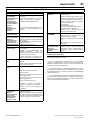
Warranty
The Company warrants that the equipment manufactured by it and delivered hereunder will be free of defects in
material and workmanship for a period of twelve months from the date of placing the Equipment in operation or eighteen
months from the date of shipment from the factory, whichever shall first occur. The Purchaser shall be obligated to
promptly report any failure to conform to this warranty, in writing to the Company in said period, whereupon the
Company shall, at its option, correct such nonconformity, by suitable repair to such equipment or, furnish a replacement
part F.O.B. point of shipment, provided the Purchaser has stored, installed, maintained and operated such Equipment
in accordance with good industry practices and has complied with specific recommendations of the Company.
Accessories or equipment furnished by the Company, but manufactured by others, shall carry whatever warranty the
manufacturers have conveyed to the Company and which can be passed on to the Purchaser. The Company shall
not be liable for any repairs, replacements, or adjustments to the Equipment or any costs of labor performed by the
Purchaser or others without Company‘s prior written approval.
The effects of corrosion, erosion and normal wear and tear are specifically excluded. Performance warranties are
limited to those specifically stated within the Company‘s proposal. Unless responsibility for meeting such performance
warranties are limited to specified tests, the Company‘s obligation shall be to correct in the manner and for the period
of time provided above.
THE COMPANY MAKES NO OTHER WARRANTY OR REPRESENTATION OF ANY KIND WHATSOEVER,
EXPRESSED OR IMPLIED, EXCEPT THAT OF TITLE, AND ALL IMPLIED WARRANTIES OF MERCHANTABILITY
AND FITNESS FOR A PARTICULAR PURPOSE, ARE HEREBY DISCLAIMED.
Correction by the Company of nonconformities whether patent or latent, in the manner and for the period of time
provided above, shall constitute fulfillment of all liabilities of the Company for such nonconformities whether based on
contract, warranty negligence, indemnity, strict liability or otherwise with respect to or arising out of such Equipment.
The purchaser shall not operate Equipment which is considered to be defective, without first notifying the Company
in writing of its intention to do so. Any such use of Equipment will be at Purchaser‘s sole risk and liability.
Note that this is Ingersoll Rand standard warranty. Any warranty in force at the time of purchase of the compressor
or negotiated as part of the purchase order may take precedence over this warranty.
Register on–line at http://air.ingersollrand.com
Ingersoll Rand Air Solutions Group
Global Aftermarket Division
800–B Beaty Street
Davidson, NC 28036
1–800–526–3615

CONTENTS & ABBREVIATIONS
1
SSR UP6 40, SSR UP6 50PE, SSR UP6 50PEI, HF50–PE, EP50–PE, HP50–PE, HXP50–PEhttp://air.ingersollrand.com
CONTENTS
1 CONTENTS
2 FOREWORD
3 DECALS
8 SAFETY
10 GENERAL INFORMATION
12 INSTALLATION / HANDLING
OPERATING INSTRUCTIONS
21 – GENERAL
22 – ELECTRO–PNEUMATIC
29 – INTELLISYS
40 MAINTENANCE
47 TROUBLE SHOOTING
ABBREVIATIONS & SYMBOLS
#### Contact Ingersoll Rand for serial number
–>#### Up to Serial No.
####–> From Serial No.
* Not illustrated
{ Option
NR Not required
AR As required
SM Sitemaster/Sitepack
HA High ambient machine
WC Watercooled machine
AC Aircooled machine
ERS Energy recovery system
T.E.F.C. Totally enclosed fan cooled motor (IP55)
O.D.P. Open drip proof (motor)

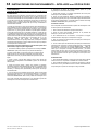
FOREWORD
2
SSR UP6 40, SSR UP6 50PE, SSR UP6 50PEI, HF50–PE, EP50–PE, HP50–PE, HXP50–PE http://air.ingersollrand.com
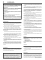
The contents of this manual are considered to be proprietary and
confidential to Ingersoll Rand and should not be reproduced without
the prior written permission of Ingersoll Rand.
Nothing contained in this document is intended to extend any
promise, warranty or representation, expressed or implied, regarding
the Ingersoll Rand products described herein. Any such warranties or
other terms and conditions of sale of products shall be in accordance
with the standard terms and conditions of sale for such products, which
are available upon request.
This manual contains instructions and technical data to cover
routine operation and scheduled maintenance tasks by operation and
maintenance staff. Major overhauls are outside the scope of this
manual and should be referred to an authorised Ingersoll Rand service
department.
The design specification of this machine has been certified as
complying with E.C. directives. Any modification to any part is
absolutely prohibited and would result in the CE certification and
marking being rendered invalid.
All components, accessories, pipes and connectors added to the
compressed air system should be:
. of good quality, procured from a reputable manufacturer and,
wherever possible, be of a type approved by Ingersoll Rand.
. clearly rated for a pressure at least equal to the machine maximum
allowable working pressure.
. compatible with the compressor lubricant/coolant.
. accompanied with instructions for safe installation, operation and
maintenance.
Details of approved equipment are available from Ingersoll Rand
Service departments.
The use of non–genuine spare repair parts other than those
included within the Ingersoll Rand approved parts list may create
hazardous conditions over which Ingersoll Rand has no control.
Therefore Ingersoll Rand does not accept any liabilitity for losses
caused by equipment in which non–approved repair parts are installed.
Standard warranty conditions may be affected.
Ingersoll Rand reserves the right to make changes and
improvements to products without notice and without incurring any
obligation to make such changes or add such improvements to
products sold previously.
The intended uses of this machine are outlined below and examples
of unapproved usage are also given, however Ingersoll Rand cannot
anticipate every application or work situation that may arise.
IF IN DOUBT CONSULT SUPERVISION.
This machine has been designed and supplied for use only in the
following specified conditions and applications:
. Compression of normal ambient air containing no known or
detectable additional gases, vapours. or particles
. Operation within the ambient temperature range specified in the
GENERAL INFORMATION section of this manual.
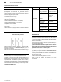
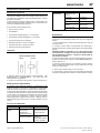
The use of the machine in any of the situation types listed in
table 1:–
a) Is not approved by Ingersoll Rand,
b) May impair the safety of users and other persons, and
c) May prejudice any claims made against Ingersoll Rand.
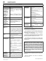
TABLE 1
Use of the machine to produce compressed air for:
a) direct human consumption
b) indirect human consumption, without suitable filtration and purity
checks.
Use of the machine outside the ambient temperature range
specified in the GENERAL INFORMATION SECTION of this manual.
Use of the machine where there is any actual or foreseeable risk of
hazardous levels of flammable gases or vapours.
THIS MACHINE IS NOT INTENDED AND MUST NOT BE
USED IN POTENTIALLY EXPLOSIVE ATMOSPHERES,
INCLUDING SITUATIONS WHERE FLAMMABLE GASES OR
VAPOURS MAY BE PRESENT.
Use of the machine fitted with non Ingersoll Rand approved
components.
Use of the machine with safety or control components missing or
disabled.
The company accepts no responsibility for errors in translation of
this manual from the original English version.
© COPYRIGHT 2008
INGERSOLL RAND COMPANY

DECALS 3
SSR UP6 40, SSR UP6 50PE, SSR UP6 50PEI, HF50–PE, EP50–PE,
HP50–PE, HXP50–PE
http://air.ingersollrand.com
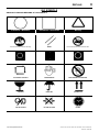
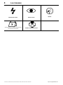
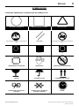
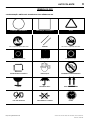
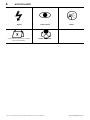
ISO SYMBOLS
GRAPHIC FORM AND MEANING OF ISO SYMBOLS
Prohibition / Mandatory Information / Instructions Warning
Use fork lift truck from this side only. RESET Do not use fork lift truck from this side.
Emergency stop. On (power). Off (power).
AUTOMATIC RESTART MAINTENANCE MAINTENANCE PROHIBITED
FRAGILE KEEP DRY THIS WAY UP
USE NO HOOKS NO SIDE CLAMPS HOURS

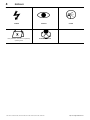
DECALS4
SSR UP6 40, SSR UP6 50PE, SSR UP6 50PEI, HF50–PE, EP50–PE, HP50–PE, HXP50–PE http://air.ingersollrand.com
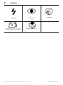
POWER INSPECT
Every X months, if sooner than required by
operating hours
CHANGE / REPLACE
CLEAN

DECALS 5
SSR UP6 40, SSR UP6 50PE, SSR UP6 50PEI, HF50–PE, EP50–PE,
HP50–PE, HXP50–PE
http://air.ingersollrand.com
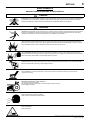
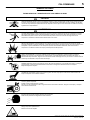
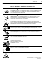
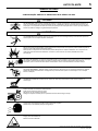
ANSI SYMBOLS
GRAPHIC FORM AND MEANING OF ANSI SYMBOLS
DANGER
INTAKE AIR. Can contain carbon monoxide or other contaminants. Will cause serious injury or death. Ingersoll Rand
air compressors are not designed, intended or approved for breathing air. Compressed air should not be used for
breathing air applications unless treated in accordance with all applicable codes and regulations.
WARNING
HAZARDOUS VOLTAGE. Can cause serious injury or death. Disconnect power and bleed pressure from tank before
servicing. Lockout/Tagout machine. Compressor must be connected to properly grounded circuit. See Grounding
Instructions in manual. Do not operate compressor in wet conditions. Store indoors.
RISK OF FIRE OR EXPLOSION. Electrical arcing from compressor components can ignite flammable liquids and
vapors which can result in serious injury. Never operate the compressor near flammable liquids or vapors. If used to
spray flammable materials, keep compressor at least 20ft away from the spray area.
HIGH PRESSURE AIR. Rusted tanks can cause explosion and severe injury or death. Receiver under perssure.
Operator should relieve tank pressure before performing maintenance. In addition to automatic drain, operate manual
drain valve weekly. Manual drain valve located at bottom of the tank.
MOVING PARTS. Can cause serious injury. Do not operate with guards removed. Machine may start automatically.
Disconnect power before servicing. Lockout/Tagout machine.
HOT SURFACES. Can cause serious injury. Do not touch. Allow to cool before servicing. Do not touch hot
compressor or tubing.
EXPOSED MOVING BELTS AND SHEAVES.
Can cause severe injury or death.
Do not operate without guard in place. Disconnect power before servicing.
Lockout/Tagout machine.
Air flow exhaust may contain flying debris.
Safety protection should be worn at all times.
Pinch point hazard.
Keep hands clear.

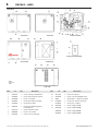
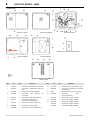
DECALS – ANSI
6
SSR UP6 40, SSR UP6 50PE, SSR UP6 50PEI, HF50–PE, EP50–PE, HP50–PE, HXP50–PE http://air.ingersollrand.com
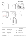
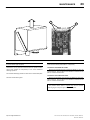
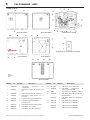
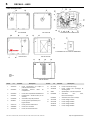
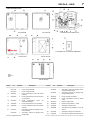
VIEW BACK
VIEW LEFT
INSIDE PACKAGE
INSIDE STARTER DOOR
VIEW FRONT
VIEW RIGHT
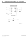
60 Hz Units
VIEW TOP
Item ccn Qty. Description Item ccn Qty. Description
1 32343519 1 Decal, warning contaminated air
2 93166502 1 Decal, replacement filter element
3 93166460 1 Decal, coolant drain
4 32343501 1
Decal, dual voltage (if needed)
5 22248538 2 Decal, pinch hazard
6 23038474 1 Decal, Ingersoll Rand signature
horizontal 27.5“
7
23353170 1 Decal, maintenance parts
8 30286686 1 Decal, notice rotation
9 32343543 1 Decal, notice air discharge
10 93171262 2 Decal, notice lift here
11 32343493 1 Decal, overload setting IEC starter
12 SPEC 1 Specifications, compressor package
13 81295883 1 Decal, facia – Electro–Pneumatic
81295891 1 Decal, facia – Intellisys
14 32017469 1 Decal, voltage 120/1/60
15 32017436 1 Decal, voltage 230/3/60
32018475 1 Decal, voltage 200/3/60
32236481 1 Decal, voltage 380/3/60

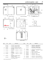
7
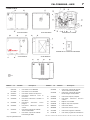
DECALS – ANSI
SSR UP6 40, SSR UP6 50PE, SSR UP6 50PEI, HF50–PE, EP50–PE, HP50–PE, HXP50–PEhttp://air.ingersollrand.com
VIEW BACK
VIEW LEFT
INSIDE PACKAGE
INSIDE STARTER DOOR
VIEW FRONT
VIEW RIGHT
60 Hz Units
VIEW TOP
Item ccn Qty. Description Item ccn Qty. Description
32017444 1 Decal, voltage 460/3/60
32177305 1 Decal, voltage 575/3/60
16 32343527 1 Decal, warning high pressure
17 32343535 3 Decal, warning moving belts
18 32343550 4 Decal, warning exposed fan
19 32343568 2 Decal, warning hazardous voltage
20 32343584 1 Decal, warning hot surface
21 22182372 1 Decal, wiring schematic
Full Voltage 60Hz
22182349 1 Decal, wiring schematic
Star Delta 60Hz
22182364 1 Decal, wiring schematic
Full Voltage Intellisys 60Hz
22182356 1 Decal, wiring schematic
Star Delta Intellisys 60Hz
22 32343907 1 Decal, lock and tag out
23 32343899 1 Decal, warning flying debris
24 22115703 1 Tag, rotation 60Hz
25 22436760 4 Tag, shipping bracket
26 22064562 1 Decal, aircare
27 30286686 1 Decal, rotation arrow
28 22181663 1 Decal, condensate drain
29 81296196 1 Decal, maintenance schedule

SAFETY
8
SSR UP6 40, SSR UP6 50PE, SSR UP6 50PEI, HF50–PE, EP50–PE, HP50–PE, HXP50–PE http://air.ingersollrand.com
DANGER!
Hazard that WILL cause DEATH, SEVERE INJURY or substantial
property damage if ignored. Instructions must be followed precisely to
avoid injury or death.
WARNING!
Hazard that CAN cause DEATH, SEVERE INJURY or substantial
property damage if ignored. Instructions which must be followed
precisely to avoid injury or death.
CAUTIONS!
Cautions call attention to instructions which must be followed
precisely to avoid damaging the product, process or its surroundings.
NOTES
Notes are used for supplementary information.
BREATHING AIR PRECAUTION
Ingersoll Rand air compressors are not designed, intended or
approved for breathing air. Compressed air should not be used for
breathing air applications unless treated in accordance with all
applicable codes and regulations.
General Information
Ensure that the operator reads and understands the decals and
consults the manuals before maintenance or operation.
Ensure that the Operation and Maintenance manual is not removed
permanently from the machine.
Ensure that maintenance personnel are adequately trained,
competent and have read the Maintenance Manuals.
Do not point air nozzles or sprayers toward anyone.
Compressed air and electricity can be dangerous. Before
undertaking any work on the compressor, ensure that the electrical
supply has been isolated and the compressor has been relieved of all
pressure.
Wear eye protection when operating or servicing compressor.
All persons positioned near to operating machinery should be
equipped with hearing protection and given instructions on its use in
accordance with workplace safety legislation.
Make sure that all protective covers are in place and that the
canopy/doors are closed during operation.
The specification of this machine is such that the machine is not
suitable for use in flammable gas risk areas.
Installation of this compressor must be in accordance with
recognised electrical codes and any local Health and Safety Codes.
The use of plastic bowls on line filters can be hazardous. Their
safety can be affected by either synthetic lubricants, or the additives
used in mineral oils. Ingersoll –Rand recommends that only filters with
metal bowls should be used on a pressurised system.
Compressed air
Compressed air can be dangerous if incorrectly handled. Before
doing any work on the unit, ensure that all pressure is vented from the
system and that the machine cannot be started accidentally.
WARNING
Imposing a normal or emergency stop on the compressor will
only relieve presure upstream of the minimum pressure valve on
top of the separator tank.
If maintenance work is required downstream of this valve, ensure
that all pressure is relieved at the process vent point external to
the compressor
Ensure that the machine is operating at the rated pressure and that
the rated pressure is known to all relevant personnel.
All air pressure equipment installed in or connected to the machine
must have safe working pressure ratings of at least the machine rated
pressure.
If more than one compressor is connected to one common
downstream plant, effective isolation valves must be fitted and
controlled by work procedures, so that one machine cannot accidently
be pressurised / over pressurised by another.
Compressed air must not be used for a direct feed to any form of
breathing apparatus or mask.
The discharged air contains a very small percentage of compressor
lubricant and care should be taken to ensure that downstream
equipment is compatible.
If the discharged air is to be ultimately released into a confined
space, adequate ventilation must be provided.
When using compressed air always use appropriate personal
protective equipment.
All pressure containing parts, especially flexible hoses and their
couplings, must be regularly inspected, be free from defects and be
replaced according to the Manual instructions.
Compressed air can be dangerous if incorrectly handled. Before
doing any work on the unit, ensure that all pressure is vented from the
system and that the machine cannot be started accidentally.
Avoid bodily contact with compressed air.
All safety valves located in the separator tank must be checked
periodically for correct operation.
Do not over–pressurize the receiver tank or similar vessels beyond
design limits.
Do not use a receiver tank or similar vessels that fail to meet the
design requirements of the compressor. Contact your distributor for
assistance.
Do not drill into, weld or otherwise alter the receiver tank or similar
vessels.
Materials
The following substances are used in the manufacture of this
machine and may be hazardous to health if used incorrectly:
. preservative grease
. rust preventative
. compressor coolant
AVOID INGESTION, SKIN CONTACT AND INHALATION OF
FUMES
Transport
When loading or transporting machines ensure that the specified
lifting and tie down points are used.
Lifting equipment must be properly rated for the weight of the
compressor.
Do not work on or walk under the compressor while it is suspended.
Electrical
Keep all parts of the body and any hand–held tools or other
conductive objects, away from exposed live parts of the compressor
electrical system. Maintain dry footing, stand on insulating surfaces
and do not contact any other portion of the compressor when making
adjustments or repairs to exposed live parts of the compressor
electrical system.
WARNING
Any electrical connections or adjustments should only be
made by a suitably qualified electrician
Close and lock all access doors when the compressor is left
unattended.
Do not use extinguishers intended for Class A or Class B fires on
electrical fires. Use only extinguishers suitable for class BC or class
ABC fires.

SAFETY
9
SSR UP6 40, SSR UP6 50PE, SSR UP6 50PEI, HF50–PE, EP50–PE, HP50–PE,
HXP50–PE
http://air.ingersollrand.com
Attempt repairs only in clean, dry, well lighted and ventilated areas.
Connect the compressor only to electrical systems that are
compatible with its electrical characteristics and that are within it’s rated
capacity.
Condensate disposal
As waste water regulations vary by country and region it is the
responsibility of the user to establish the limitations and regulations in
their particular area. Ingersoll Rand and its associated distributors are
happy to advise and assist in these matters.
For further information, consult Material Data Sheets
for ULTRA Coolant.

GENERAL INFORMATION
10
SSR UP6 40, SSR UP6 50PE, SSR UP6 50PEI, HF50–PE, EP50–PE,
HP50–PE, HXP50–PE
http://air.ingersollrand.com
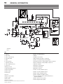
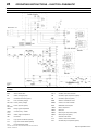
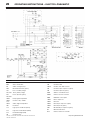
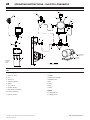
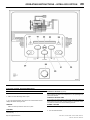
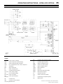
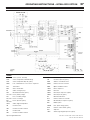
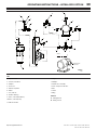
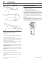
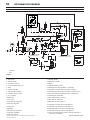
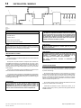
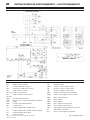
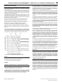
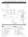
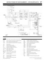
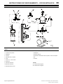
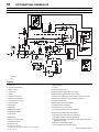
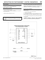
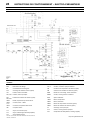
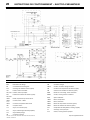
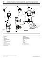
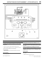
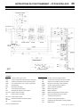
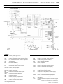
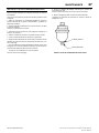
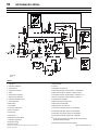
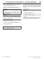
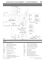
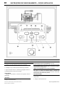
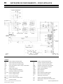
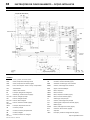
PIPING AND INSTRUMENTATION – Electro–pneumatic and Intellisys Units
KEY
1. Filter, air
2. Valve, inlet
3. Valve, solenoid (load)
4. Airend assembly
5. Motor
6. Tank, separator
7. Separator elements
8. Valve, minimum pressure
9. Aftercooler
10.Gauge, pressure
11.Switch, discharge pressure
12.Switch, temperature
13.Filter, coolant
14.Thermostat
15.Cooler
16 Relay, overload, Motor
17.Valve, safety
18.Valve, drain
19.Screen, scavenge
20 Valve, solenoid (blowdown)
21.Orifice
22 Indicator, air restriction
23.Electric drain valve (EDV – condensate)
24.Valve solenoid (line/sump), Intellisys Option
25.Transducer pressure, Intellisys Option, replaces 10 and 11
26.Sensor temperature, Intellisys Option, replaces 12
27.Moisture separator
28.Compressor air discharge
29.Condensate discharge
30.Compressor air inlet
31.Valve, solenoid, (modulation option)
32.Valve, solenoid, (modulation option)
33.Valve, shuttle, (modulation option)
34.Valve, modulation (modulation option)
35.Sensor, temperature, dryer (option) thermometer or
thermistor–Intellisys
36.Valve, expansion, dryer (option)
37.Filter, refrigerant, dryer (option)
4
1
2
9
18
13
8
10
15
17
19
12
14
16
20
5
11
7
3
21
6
22
PIPING LEGEND
A
B
C
D
E
24
25
26
27
23
29
30
INTELLISYS (OPTION)
REPLACES ITEM 12
INTELLISYS (OPTION)
REPLACES ITEMS 10 & 11
F
G
DRYER
OPTION
32
33
31
34
MODULATION (OPTION)
T
M
T
P
28
M
39
35
38
40
41
37
36
27
22292783
Rev F

GENERAL INFORMATION
11
SSR UP6 40, SSR UP6 50PE, SSR UP6 50PEI, HF50–PE,
EP50–PE, HP50–PE, HXP50–PE
http://air.ingersollrand.com
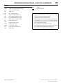
38.Condenser, dryer (option)
39.Evaporator, dryer (option)
40.Refrigerant compressor, dryer (option)
41.Hot gas bypass valve, dryer (option)
A Air/Coolant
B Air
C Coolant
D Condensate
E Component boundary
F Refrigerant
G Option

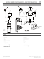
INSTALLATION / HANDLING
12
SSR UP6 40, SSR UP6 50PE, SSR UP6 50PEI, HF50–PE, EP50–PE,
HP50–PE, HXP50–PE
http://air.ingersollrand.com
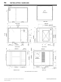
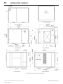
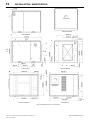
ROTATION
VIEW LEFT
VIEW FRONT VIEW RIGHT
VIEW TOPVIEW BOTTOM
VIEW REAR
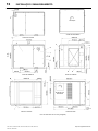
Note: Dimensions are mm (inches)
DRYER
ROTATION

INSTALLATION / HANDLING
13
SSR UP6 40, SSR UP6 50PE, SSR UP6 50PEI, HF50–PE, EP50–PE,
HP50–PE, HXP50–PE
http://air.ingersollrand.com
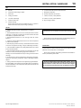
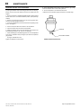
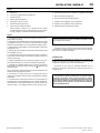
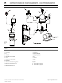
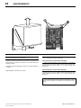
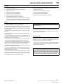
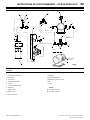
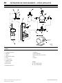
KEY
A Pre filter
B Compressor and cooling air intake
C Starter box
D Cooling air exhaust
E 1.5” NPT air discharge
F Customer power inlet
G Fork lift openings
(Fork lift hole covers must be installed after unit is in place to
reduce noise and ensure proper cooling of package)
H .25 Inch female NPT moisture separator drain.
J Emergency stop button
K Primary compressor service door
L 4 holes, 0.67 Inch (17mm) diameter
M 4 holes, 0.47 Inch (12mm) diameter
N Dryer cooling air intake
NOTES
1. Coolant (lubricant) fill quantity (approximate) 5.5 US gallons
(21 litres).
2. Recommended clearance in front of control panel door 42 inches
(1067 mm) or minimum as required by the latest national electrical
codes (NEC) or applicable local codes.
3. Recommended clearances on left and right sides 36 inches
(914mm).
4. Minimum recommended clearance for the rear of the compressor
is to be 6 inches (152mm).
5. External piping shall not exert any unresolved moments or forces
on the unit. Use pipe size as large or larger at discharge connection.
6. There should be no plastic or pvc piping attached to this unit or used
for any lines downstream.
7. Any field installed ducting to and from the compressor cannot add
more than 1/2 inch (12.5mm) water gauge total air resistance.
Ducting is not recommended for the dryer cooling air inlet and outlet
openings.
8. Do not pipe into a common header with a reciprocating compressor,
unless the reciprocating compressor utilizes a discharge pulsation
damper.
9. Sizing of electrical components not supplied by Ingersoll Rand is
the responsibility of the customer and should be done in accordance
with the information on the compressor data plate and national and
local electrical codes.
NOTE
All dimensions are in millimetres (inches) unless otherwise stated.
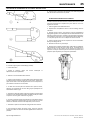
Ensure that the correct fork lift truck slots or marked lifting points are
used whenever the machine is lifted or transported.
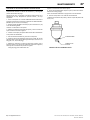
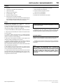
UNPACKING
The compressor will normally be delivered with a polythene cover.
If a knife has to be used to remove this cover ensure that the exterior
paintwork of the compressor is not damaged.
Ensure that all transport and packing materials are discarded in a
manner prescribed by local codes.
NOTE
Units are shipped with transit locking bolt in place. Prior to
running the unit the shipping bolt must be removed and the belt
tension checked. Loosen, remove and discard 10mm shipping
bolt. For belt tensioning procedure refer to Maintenance section.

INSTALLATION / HANDLING
14
SSR UP6 40, SSR UP6 50PE, SSR UP6 50PEI, HF50–PE, EP50–PE,
HP50–PE, HXP50–PE
http://air.ingersollrand.com
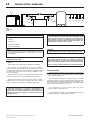
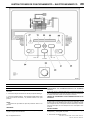
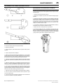
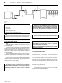
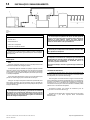
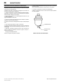
KEY
1. Compressor
2. Air Dryer
3. Air Receiver
4. Compressed air filters
5. System demand points
NOTE
Items [2] to [5] are optional or may be existing items of plant. Refer
to your Ingersoll Rand distributor / representative for specific
recommendations.
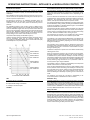
LOCATION IN THE PLANT
Note:
Ensure that the unit is wired for proper voltage before installation.
The compressor can be installed on any level floor capable of
supporting it. A dry, well ventilated area where the atmosphere is clean
is recommended. A minimum of 6 inches (150mm) should be left at the
rear and 3ft (1m) at the sides of the machine for adequate service
access and ventilation.
Adequate clearance needs to be allowed around and above the
machine to permit safe access for specified maintenance tasks.
Ensure that the machine is positioned securely and on a stable
foundation. Any risk of movement should be removed by suitable
means, especially to avoid strain on any rigid discharge piping.
CAUTION
Screw type compressors [1] should not be installed in air
systems with reciprocating compressors without means of
isolation such as a common receiver tank. It is recommended that
both types of compressor be piped to a common receiver using
individual air lines.
CAUTION
The use of plastic bowls on line filters and other plastic air line
components can be hazardous. Their safety can be affected by
either synthetic coolants or the additives used in mineral oils.
Ingersoll Rand recommends that only filters with metal bowls
should be used on any pressurised system.
CAUTION
Before starting machine remove shipping bolt and discard
CAUTION
The standard compressor unit is not suitable for operation in
temperatures liable to cause freezing as Condensate water is
liable to be produced in the after cooler and receiver where fitted.
Refer to your Ingersoll Rand distributor for further information.
DISCHARGE PIPING
Discharge piping should be at least as large as the discharge
connection of the compressor. All piping and fittings should be suitably
rated for the discharge pressure.
It is essential when installing a new compressor [1], to review the
total air system. This is to ensure a safe and effective total system. One
item which should be considered is liquid carryover. Installation of air
dryers [3] is always good practice since properly selected and installed
they can reduce any liquid carryover to zero.
It is good practice to locate an isolation valve close to the
compressor and to install line filters [4].
It is a requirement for air dryers covered under Aircare that correctly
sized Ingersoll Rand pre and afterfilters are installed.
5
3
4
4
2
1
T5750
Revision 02
07/04

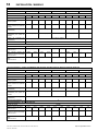
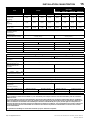
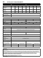
INSTALLATION / HANDLING
15
SSR UP6 40, SSR UP6 50PE, SSR UP6 50PEI, HF50–PE, EP50–PE,
HP50–PE, HXP50–PE
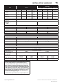
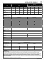
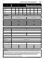
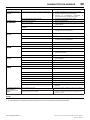
60Hz UP6 40
UP6 50PE
UP6 50PEI
60Hz
UP6 40
HF50–PE EP50–PE HP50–PE HXP50–PE
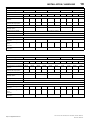
COMPRESSOR 115 125 150 200 115 125 150 200
Maximum operating pressure
psig (barg)
115
(8.0)
125
(8.5)
150
(10.3)
200
(13.8)
115
(8.0)
125
(8.5)
150
(10.3)
200
(13.8)
Factory set reload pressure
psig (barg)
105
(7.2)
115
(7.9)
140
(9.6)
190
(13.1)
105
(7.2)
115
(7.9)
140
(9.6)
190
(13.1)
Flow rate
cfm (m
3
/min)
188
(5.32)
185
(5.24)
170
(4.81)
143
(4.05)
212
(6.02)
208
(5.89)
201
(5.70)
167
(4.73)
Maximum airend discharge
temperature
216 F (102 C)
Ambient operating
temperature
min. max.
36 F(+2 C ) ? 105 F(+40 C) 36 F(+2 C ) ? 115 F(+46 C)
MOTOR
Motor enclosure ODP TEFC ODP TEFC
Nominal power 40HP 50HP
Speed 1775 RPM 1775 RPM
Frame 324T 324T 326T 326T
Insulation class F
COOLING SYSTEM – Air cooled
Cooling air flow 3100 ft
3
/min (87.8m
3
/min) 3900 ft
3
/min (110m
3
/min)
Dryer cooling air flow 1200 ft
3
/min (34m
3
/min)
Maximum ∆P in air ducts 0.5 inWg (12.7mmH
2
O) (not recommended for dryer openings)
Compressed air outlet ∆T
15 F (8.3 C) 15 F (8.3 C)
Cooling air outlet ∆T
40 F (22 C) 42 F (23 C)
Dryer cooling air outlet ∆T
11 F (6 C)
GENERAL DATA
Residual coolant content 3ppm (3 mg/m
3
)
Separator vessel capacity 3.7 US gallons (14 liters)
Coolant capacity 5.5 US gallons (21 liters)
Sound pressure level to
CAGI–PNEUROP
69 dB(A) 69 dB(A)
(Non–dryer unit)
Weight – base mount unit 2326 lbs
(1055 kg)
2436 lbs
(1105 kg)
2384 lbs
(1081 kg)
2476 lbs
(1123 kg)
Weight – dryer option unit 2576 lbs
(1168 kg)
2686 lbs
(1218 kg)
2634 lbs
(1194 kg)
2726 lbs
(1236 kg)
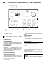
CAUTION
230/460 Dual voltage machines are fitted with a decal to advise
the correct supply voltage as connected from the factory.
Factory units wired for 230V supply can be re–wired to 460V
supply voltage by re–wiring the main drive motor and the fan
motor as shown on the electrical schematic AND by replacing
the fan motor starter CCN 22395800 - 50HP with CCN 22395792
- 50 HP (shipped loose). The main motor overload and the fan
motor starter overload settings should be adjusted accordingly –
reference the IEC decal mounted inside the starter door. Also,
the transformer primary voltage connections will need to be
re–wired for the new supply voltage.
Re–wiring should only be effected by a competent Electrician.
http://air.ingersollrand.com

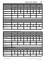
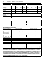
INSTALLATION / HANDLING
16
SSR UP6 40, SSR UP6 50PE, SSR UP6 50PEI, HF50–PE, EP50–PE,
HP50–PE, HXP50–PE
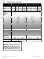
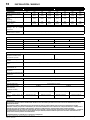
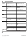
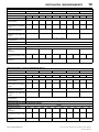
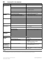
60Hz UP6 30E–HA UP6 40–HA
COMPRESSOR 115 125 150 200 115 125 150 200
Maximum operating pressure
psig (barg)
125
(8.5)
150
(10.3)
200
(13.8)
115
(8.0)
125
(8.5)
150
(10.3)
200
(13.8)
Factory set reload pressure
psig (barg)
115
(7.9)
140
(9.6)
190
(13.1)
105
(7.2)
115
(7.9)
140
(9.6)
190
(13.1)
Flow rate
cfm (m
3
/min)
125
(3.54)
112
(3.17)
92
(2.61)
188
(5.32)
185
(5.24)
170
(4.81)
143
(4.05)
Maximum airend discharge
temperature
216_F (102_C)
Ambient operating
temperature
min. →max.
36_F(+2_C ) → 122_F(+50_C)
MOTOR
Motor enclosure ODP TEFC ODP TEFC
Nominal power 30HP 40HP
Speed 1775 RPM
Frame 324T 324T 326T 326T
Insulation class F
COOLING SYSTEM – Air cooled
Cooling air flow 3100 ft
3
/min (87.8m
3
/min) 3900 ft
3
/min (110m
3
/min)
Dryer cooling air flow 1200 ft
3
/min (34m
3
/min)
Maximum ∆P in air ducts 0.5 inWg (12.7mmH
2
O) (not recommended for dryer openings)
Compressed air outlet ∆T
15_F (8.3_C)
Cooling air outlet ∆T
40_F (22_C) 42_F (23_C)
Dryer cooling air outlet ∆T
11_F (6_C)
GENERAL DATA
Residual coolant content 3ppm (3 mg/m
3
)
Separator vessel capacity 3.7 US gallons (14 liters)
Coolant capacity 5.5 US gallons (21 liters)
Sound pressure level to
CAGI–PNEUROP
69 dB(A) 69 dB(A)
(Non–dryer unit)
Weight – base mount unit 2326 lbs
(1055 kg)
2436 lbs
(1105 kg)
2384 lbs
(1081 kg)
2476 lbs
(1123 kg)
Weight – dryer option unit 2576 lbs
(1167 kg)
2686 lbs
(1218 kg)
2634 lbs
(1194 kg)
2726 lbs
(1236 kg)
CAUTION
230/460 Dual voltage machines are fitted with a decal to advise
the correct supply voltage as connected from the factory.
Factory units wired for 230V supply can be re–wired to 460V
supply voltage by re–wiring the main drive motor and the fan
motor as shown on the electrical schematic AND by replacing
the fan motor starter CCN 22395800 - 50 HP with CCN 22395792 -
50 HP (shipped loose). The main motor overload and the fan
motor starter overload settings should be adjusted accordingly –
reference the IEC decal mounted inside the starter door. Also,
the transformer primary voltage connections will need to be
re–wired for the new supply voltage.
Re–wiring should only be effected by a competent Electrician.
http://air.ingersollrand.com

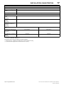
INSTALLATION / HANDLING
17
SSR UP6 40, SSR UP6 50PE, SSR UP6 50PEI, HF50–PE, EP50–PE,
HP50–PE, HXP50–PE
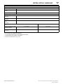
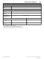
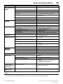
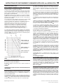
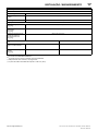
DRYER OPTION TECHNICAL INFORMATION 60Hz
General
Refrigerant type R404A
Refrigerant charge
kg (lbs)
1.8 (0.84)
Refrigerant oil Emkarate RL32CF or Texaco Capella HFC32
Control settings
Hot gas setting
barg (psig)
72 – 74 (5.0 – 5.1)
High pressure switch setting
barg (psig)
425 (29.3)
Fan pressure switch setting
on/off
barg (psig)
225 / 175 (15.5 / 12.1)
Performance
(2)
(3)
30 / 40HP 50HP
Dew point temperature at rated
conditions and flow
(3)
41_F (5_C)
(4)
50_F (10_C)
Maximum ∆P across dryer
barg (psig)
2.2 (0.15) 3.0 (0.21)
(1)
In accordance with PNEUROP PN8NTC2.3
(2)
In accordance with ISO 7183 at the modified rated conditions.
(3)
60Hz machines: 85_F ambient, 125 psig inlet.
(4)
40hp 200v unit dewpoint is 50_F (10_C)
http://air.ingersollrand.com

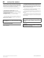
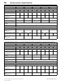
INSTALLATION / HANDLING
18
SSR UP6 40, SSR UP6 50PE, SSR UP6 50PEI, HF50–PE, EP50–PE,
HP50–PE, HXP50–PE
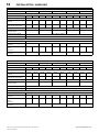
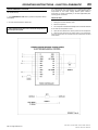
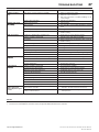
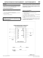
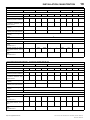
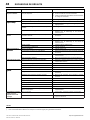
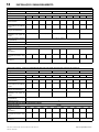
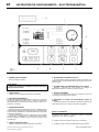
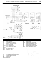
ELECTRICAL DATA – ALL UNITS SSR UP6–40
Standard voltage 200V 230V 380V 460V 575V
PACKAGE
Motor enclosure ODP TEFC ODP TEFC ODP TEFC ODP TEFC ODP TEFC
Power (nominal) 40HP
Full load current at maximum
pressure
136.0A 125.6A 118.3A 109.2A 71.6A 66.1A 59.2A 54.6A 47.3A 43.7A
Full load current at maximum
pressure with dryer option
143.7A 133.3A 125.2A 116.1A – – 62.5A 57.9A – –
Starting current FV (STAR) 706.1 (264.5) 614 (230) 367 (135.2) 307 (115) 245.6 (92)
Starting current FV (STAR)
with dryer option
744.4 (302.5) 652 (268) – 323 (131) –
Starting time FV (STAR) 3–5 Sec (7–10 Sec)
Starts per hour (maximum) 6
ELECTRICAL DATA – FV / Star Delta
Control voltage 120VAC
Minimum fuse rating
See note 1
175A 150A 100A 90A 75A 60A
Minimum fuse rating with dryer
option
See note 1
200A 175A 175A 150A – – 80A 75A – –
Minimum wire size AWG
See note 2
4/0 3/0 2 3 4
ELECTRICAL DATA – ALL UNITS SSR UP6 50PE, UP6 50PEI, HF50–PE, EP50–PE, HP50–PE and HXP50–PE
Standard voltage 200V 230V 380V 460V 575V
PACKAGE
Motor enclosure ODP TEFC ODP TEFC ODP TEFC ODP TEFC ODP TEFC
Power (nominal) 50HP
Full load current at maximum
pressure
170.8A 160.0A 148.5A 139.1A 89.8A 82.2A 74.2A 67.9A 59.4A 55.7A
Full load current at maximum
pressure with dryer option
– – 155.4A 146.0A – – 77.5A 71.2A – –
Starting current FV (STAR) 876.3 (321.2) 762 (279.3) 461 (169.0) 381 (139.7) 304.8 (111.7)
Starting current FV (STAR)
with dryer option
– 800 (317) – 397 (156) –
Starting time FV (STAR) 3–5 Sec (7–10 Sec)
Starts per hour (maximum) 6
ELECTRICAL DATA – FV / Star Delta
Control voltage 120VAC
Minimum fuse rating
See note 1
225A 200A 200A 175A 110A 110A 100A 90A 75A 70A
Minimum fuse rating with dryer
option
See note 1
– – 200A 200A – – 100A 90A – –
Minimum wire size AWG
See note 2
250 4/0 1 2 3
http://air.ingersollrand.com
A página está carregando...
A página está carregando...
A página está carregando...
A página está carregando...
A página está carregando...
A página está carregando...
A página está carregando...
A página está carregando...
A página está carregando...
A página está carregando...
A página está carregando...
A página está carregando...
A página está carregando...
A página está carregando...
A página está carregando...
A página está carregando...
A página está carregando...
A página está carregando...
A página está carregando...
A página está carregando...
A página está carregando...
A página está carregando...
A página está carregando...
A página está carregando...
A página está carregando...
A página está carregando...
A página está carregando...
A página está carregando...
A página está carregando...
A página está carregando...
A página está carregando...
A página está carregando...
A página está carregando...
A página está carregando...
A página está carregando...
A página está carregando...
A página está carregando...
A página está carregando...
A página está carregando...
A página está carregando...
A página está carregando...
A página está carregando...
A página está carregando...
A página está carregando...
A página está carregando...
A página está carregando...
A página está carregando...
A página está carregando...
A página está carregando...
A página está carregando...
A página está carregando...
A página está carregando...
A página está carregando...
A página está carregando...
A página está carregando...
A página está carregando...
A página está carregando...
A página está carregando...
A página está carregando...
A página está carregando...
A página está carregando...
A página está carregando...
A página está carregando...
A página está carregando...
A página está carregando...
A página está carregando...
A página está carregando...
A página está carregando...
A página está carregando...
A página está carregando...
A página está carregando...
A página está carregando...
A página está carregando...
A página está carregando...
A página está carregando...
A página está carregando...
A página está carregando...
A página está carregando...
A página está carregando...
A página está carregando...
A página está carregando...
A página está carregando...
A página está carregando...
A página está carregando...
A página está carregando...
A página está carregando...
A página está carregando...
A página está carregando...
A página está carregando...
A página está carregando...
A página está carregando...
A página está carregando...
A página está carregando...
A página está carregando...
A página está carregando...
A página está carregando...
A página está carregando...
A página está carregando...
A página está carregando...
A página está carregando...
A página está carregando...
A página está carregando...
A página está carregando...
A página está carregando...
A página está carregando...
A página está carregando...
A página está carregando...
A página está carregando...
A página está carregando...
A página está carregando...
A página está carregando...
A página está carregando...
A página está carregando...
A página está carregando...
A página está carregando...
A página está carregando...
A página está carregando...
A página está carregando...
A página está carregando...
A página está carregando...
A página está carregando...
A página está carregando...
A página está carregando...
A página está carregando...
A página está carregando...
A página está carregando...
A página está carregando...
A página está carregando...
A página está carregando...
A página está carregando...
A página está carregando...
A página está carregando...
A página está carregando...
A página está carregando...
A página está carregando...
A página está carregando...
A página está carregando...
A página está carregando...
A página está carregando...
A página está carregando...
A página está carregando...
A página está carregando...
A página está carregando...
A página está carregando...
A página está carregando...
A página está carregando...
A página está carregando...
A página está carregando...
A página está carregando...
A página está carregando...
A página está carregando...
A página está carregando...
A página está carregando...
A página está carregando...
A página está carregando...
A página está carregando...
A página está carregando...
A página está carregando...
A página está carregando...
A página está carregando...
A página está carregando...
A página está carregando...
A página está carregando...
A página está carregando...
A página está carregando...
A página está carregando...
A página está carregando...
A página está carregando...
A página está carregando...
A página está carregando...
A página está carregando...
A página está carregando...
A página está carregando...
A página está carregando...
A página está carregando...
A página está carregando...
A página está carregando...
A página está carregando...
A página está carregando...
A página está carregando...
A página está carregando...
A página está carregando...
A página está carregando...
A página está carregando...
A página está carregando...
A página está carregando...
A página está carregando...
A página está carregando...
-
 1
1
-
 2
2
-
 3
3
-
 4
4
-
 5
5
-
 6
6
-
 7
7
-
 8
8
-
 9
9
-
 10
10
-
 11
11
-
 12
12
-
 13
13
-
 14
14
-
 15
15
-
 16
16
-
 17
17
-
 18
18
-
 19
19
-
 20
20
-
 21
21
-
 22
22
-
 23
23
-
 24
24
-
 25
25
-
 26
26
-
 27
27
-
 28
28
-
 29
29
-
 30
30
-
 31
31
-
 32
32
-
 33
33
-
 34
34
-
 35
35
-
 36
36
-
 37
37
-
 38
38
-
 39
39
-
 40
40
-
 41
41
-
 42
42
-
 43
43
-
 44
44
-
 45
45
-
 46
46
-
 47
47
-
 48
48
-
 49
49
-
 50
50
-
 51
51
-
 52
52
-
 53
53
-
 54
54
-
 55
55
-
 56
56
-
 57
57
-
 58
58
-
 59
59
-
 60
60
-
 61
61
-
 62
62
-
 63
63
-
 64
64
-
 65
65
-
 66
66
-
 67
67
-
 68
68
-
 69
69
-
 70
70
-
 71
71
-
 72
72
-
 73
73
-
 74
74
-
 75
75
-
 76
76
-
 77
77
-
 78
78
-
 79
79
-
 80
80
-
 81
81
-
 82
82
-
 83
83
-
 84
84
-
 85
85
-
 86
86
-
 87
87
-
 88
88
-
 89
89
-
 90
90
-
 91
91
-
 92
92
-
 93
93
-
 94
94
-
 95
95
-
 96
96
-
 97
97
-
 98
98
-
 99
99
-
 100
100
-
 101
101
-
 102
102
-
 103
103
-
 104
104
-
 105
105
-
 106
106
-
 107
107
-
 108
108
-
 109
109
-
 110
110
-
 111
111
-
 112
112
-
 113
113
-
 114
114
-
 115
115
-
 116
116
-
 117
117
-
 118
118
-
 119
119
-
 120
120
-
 121
121
-
 122
122
-
 123
123
-
 124
124
-
 125
125
-
 126
126
-
 127
127
-
 128
128
-
 129
129
-
 130
130
-
 131
131
-
 132
132
-
 133
133
-
 134
134
-
 135
135
-
 136
136
-
 137
137
-
 138
138
-
 139
139
-
 140
140
-
 141
141
-
 142
142
-
 143
143
-
 144
144
-
 145
145
-
 146
146
-
 147
147
-
 148
148
-
 149
149
-
 150
150
-
 151
151
-
 152
152
-
 153
153
-
 154
154
-
 155
155
-
 156
156
-
 157
157
-
 158
158
-
 159
159
-
 160
160
-
 161
161
-
 162
162
-
 163
163
-
 164
164
-
 165
165
-
 166
166
-
 167
167
-
 168
168
-
 169
169
-
 170
170
-
 171
171
-
 172
172
-
 173
173
-
 174
174
-
 175
175
-
 176
176
-
 177
177
-
 178
178
-
 179
179
-
 180
180
-
 181
181
-
 182
182
-
 183
183
-
 184
184
-
 185
185
-
 186
186
-
 187
187
-
 188
188
-
 189
189
-
 190
190
-
 191
191
-
 192
192
-
 193
193
-
 194
194
-
 195
195
-
 196
196
-
 197
197
-
 198
198
-
 199
199
-
 200
200
-
 201
201
-
 202
202
-
 203
203
-
 204
204
-
 205
205
-
 206
206
-
 207
207
-
 208
208


Ingersoll Rand Air Compressor EP50-PE Manual do usuário
- Categoria
- Compressores de ar
- Tipo
- Manual do usuário
em outras línguas
Outros documentos
-
Ingersoll-Rand UP6 25 HP Option Manual
-
-
-
-
-
-
-
Makita MAC3000 Manual do usuário
-
-