

www.stenner.com
2
TABLE OF CONTENTS
WARRANTY AND SERVICE POLICY............................................ 3
SAFETY INFORMATION........................ 4-5, 16-18, 21-25, 29, 32, 36
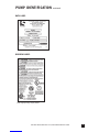
PUMP IDENTIFICATION ....................................................... 6-7
OUTPUTS ........................................................................ 8-13
MATERIALS OF CONSTRUCTION............................................. 14
ACCESSORY CHECKLIST....................................................... 15
INSTALLATION ................................................................ 16-24
TROUBLESHOOTING ........................................................ 25-28
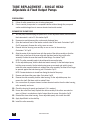
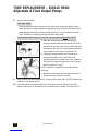
TUBE REPLACEMENT ....................................................... 30-35
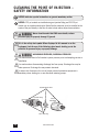
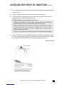
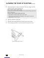
CLEANING THE POINT OF INJECTION.................................. 36-38
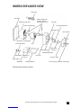
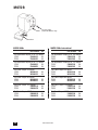
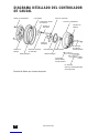
MOTOR – EXPLODED VIEW AND PARTS ............................... 39-41
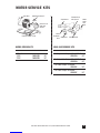
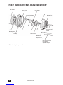
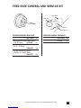
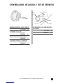
FEED RATE CONTROL – EXPLODED VIEW AND PARTS ............ 42-43
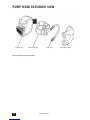
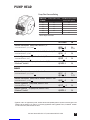
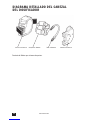
PUMP HEAD – EXPLODED VIEW AND PARTS ........................ 44-46
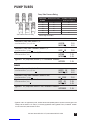
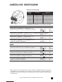
PUMP TUBES ..................................................................... 47
CHECK VALVES ................................................................... 48
FOR YOUR RECORDS ........................................................... 49
CMQ0811a

USA and Canada 800.683.2378, International 904.641.1666
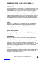
WARRANTY AND CUSTOMER SERVICE
LIMITED WARRANTY
Stenner Pump Company will for a period of one (1) year from the date of purchase (proof
of purchase required) repair or replace – at our option – all defective parts. Stenner is not
responsible for any removal or installation costs. Pump tube assemblies and rubber
components are considered perishable and are not covered in this warranty. Pump tube
will be replaced each time a pump is in for service, unless otherwise specified. The cost of
the pump tube replacement will be the responsibility of the customer. Stenner will incur
shipping costs for warranty products shipped from our factory in Jacksonville, Florida. Any
tampering with major components, chemical damage, faulty wiring, weather conditions,
water damage, power surges, or products not used with reasonable care and maintained in
accordance with the instructions will void the warranty. Stenner limits its liability solely to
the cost of the original product. We make no other warranty expressed or implied.
RETURNS
Stenner offers a 30-day return policy on factory direct purchases. Except as otherwise
provided, no merchandise will be accepted for return after 30 days from purchase. To
return merchandise at any time, call Stenner at 800.683.2378 for a Return Merchandise
Authorization (RMA) number. A 15% re-stocking fee will be applied. Include a copy of your
invoice or packing slip with your return.
DAMAGED OR LOST SHIPMENTS
All truck shipments: Check your order immediately upon arrival. All damage must be noted
on the delivery receipt. Call Stenner Customer Service at 800.683.2378 for all shortages
and damages within seven (7) days of receipt.
SERVICE & REPAIRS
Before returning a pump for warranty or repair, remove chemical from pump tube by
running water through the tube, and then run the pump dry. Following expiration of the
warranty period, Stenner Pump Company will clean and overhaul any Stenner metering
pump for a minimum labor charge plus necessary replacement parts and shipping. All
metering pumps received for overhaul will be restored to their original condition. The
customer will be charged for missing parts unless specific instructions are given. To return
merchandise for repair, call Stenner at 800.683.2378 or 904.641.1666 for a Return
Merchandise Authorization (RMA) number.
DISCLAIMER
The information contained in this manual is not intended for specific application purposes.
Stenner Pump Company reserves the right to make changes to prices, products, and
specifications at any time without prior notice.
3

www.stenner.com
4
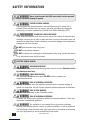
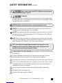
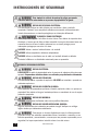
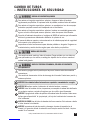
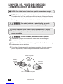
SAFETY INFORMATION
Warns about hazards that CAN cause death, serious personal
injury, or property damage if ignored.
ELECTRIC SHOCK HAZARD:
Pump supplied with grounding power cord and attached plug. To reduce risk of
electrical shock, connect only to a properly grounded, grounding type receptacle.
Install only on a circuit protected by a Ground-Fault Circuit-Interrupter (GFCI).
RISQUE DE CHOC ELECTRIQUE:
Cette pompe est équipée d’une fiche de mise à terre. Pour réduire le risque de choc
électrique, s’assurer que la fiche est bien raccordée à une prise de courant avec une
connexion de mise à terre. Installer seulement sur un circuit proteger par un interrupteur
proteger par une mise à la terre.
DO NOT alter the power cord or plug end.
DO NOT use receptacle adapters.
DO NOT use pump with a damaged or altered power cord or plug. Contact the factory
or an authorized service facility for repair.
ELECTRIC SHOCK HAZARD
HAZARDOUS VOLTAGE:
DISCONNECT power cord before removing motor cover for service. Electrical service
by trained personnel only.
EXPLOSION HAZARD:
This equipment IS NOT explosion proof. DO NOT install or operate in an
explosive environment.
RISK OF CHEMICAL EXPOSURE:
Potential for chemical burns, fire, explosion, personal injury, or property damage. To
reduce risk of exposure, the use of proper personal protective equipment is mandatory.
RISK OF FIRE HAZARD:
DO NOT install or operate on any flammable surface.
RISK OF CHEMICAL OVERDOSE:
To reduce risk, follow proper installation methods and recommendations. Check your
local codes for additional guidelines.
This appliance is not intended for use by persons (including
children) with reduced physical, sensory or mental capabilities, or lack of experience
and knowledge, unless they have been given supervision or instruction to concerning
use of the appliance by a person responsible for their safety.

USA and Canada 800.683.2378, International 904.641.1666 5
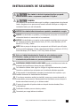
SAFETY INFORMATION continued
Warns about hazards that WILL or CAN cause minor personal
injury or property damage if ignored.
PLUMBING:
Chemical feed pump installation must always adhere to your local plumbing codes
nd requirements. Be sure installation does not constitute a cross connection. Check
local plumbing codes for guidelines.
NOTICE: Indicates special instructions or general mandatory action.
NOTICE: This metering pump is portable and designed to be removable from the
plumbing system without damage to the connections.
NOTICE: This metering pump and its components have been tested for use with the
following chemicals: Sodium Hypochlorite (10-15%), Muriatic Acid (20-22 Baume,
31.5% Hcl), and Soda Ash.
NOTE: Cette a pompe de dosage et ses composants ont été testés pour utilisation
avec les produits chimiques suivants; Hypochlorite de Sodium (solution de 10-15%);
Acide Muriatique (20-22 Baume, 31.5% Hcl); Cendre de Soude.
This is the safety alert symbol. When displayed in this manual or on the
equipment, look for one of the following signal words alerting you to the
potential for personal injury or property damage.
PUMP SUITABLE FOR USE OUTDOORS when installed with a Stenner Rain Roof Part
No. MP90000.
Electrical installation should adhere to all national and local codes. Consult a
licensed professional for assistance with proper electrical installation.
Removing power from pool/spa recirculation pump must also remove power from pump.
The use of an auxiliary safety device (not supplied), such as a flow switch or sensor,
is recommended to prevent feed pump operation in the event of a recirculation
pump failure or if flow is not sensed.
Point of chemical injection should be beyond all pumps, filters, and heaters.
Suitable for indoor and outdoor use.
Convient pour usage intérieur et extérieur.


www.stenner.com
8
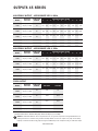
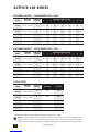
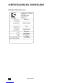
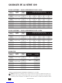
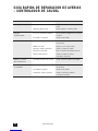
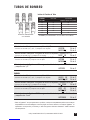
ADJUSTABLE OUTPUT – APPROXIMATE GPD @ 60Hz
OUTPUTS 45 SERIES
MODEL MAXIMUM PUMP TUBE FEED RATE CONTROL SETTING
PRESSURE NUMBER L12345678910
45MHP2* 100 psi (6.9 bar) #1 0.2 0.3 0.6 0.9 1.2 1.5 1.8 2.1 2.4 2.7 3.0
45M1 25 psi (1.7 bar)
45MHP10* 100 psi (6.9 bar) #2 0.5 1.0 2.0 3.0 4.0 5.0 6.0 7.0 8.0 9.0 10.0
45M2 25 psi (1.7 bar)
45MHP22* 100 psi (6.9 bar) #7 1.1 2.2 4.4 6.6 8.8 11.0 13.2 15.4 17.6 19.8 22.0
45M3 25 psi (1.7 bar) #3
45M4 25 psi (1.7 bar) #4 1.7 3.5 7.0 10.5 14.0 17.5 21.0 24.5 28.0 31.5 35.0
45M5 25 psi (1.7 bar) #5 2.5 5.0 10.0 15.0 20.0 25.0 30.0 35.0 40.0 45.0 50.0
MODEL MAXIMUM PUMP TUBE FEED RATE CONTROL SETTING
PRESSURE NUMBER L12345678910
45MHP2* 100 psi (6.9 bar) #1 0.6 0.9 1.8 2.7 3.6 4.5 5.5 6.4 7.3 8.2 9.1
45M1 25 psi (1.7 bar)
45MHP10* 100 psi (6.9 bar) #2 1.5 3.0 6.1 9.1 12.1 15.1 18.2 21.2 24.2 27.3 30.3
45M2 25 psi (1.7 bar)
45MHP22* 100 psi (6.9 bar) #7 3.3 6.6 13.3 20.0 26.6 33.3 40.0 46.6 53.3 60.0 66.6
45M3 25 psi (1.7 bar) #3
45M4 25 psi (1.7 bar) #4 5.1 10.6 21.2 31.8 42.4 53.0 63.6 74.2 84.8 95.4 106.0
45M5 25 psi (1.7 bar) #5 7.6 15.1 30.3 45.4 60.6 75.7 90.8 106.0 121.1 136.3 151.4
ADJUSTABLE OUTPUT – APPROXIMATE LPD @ 50Hz
FIXED OUTPUT
MODEL MAXIMUM PUMP TUBE GPD 60Hz LPD 50Hz
PRESSURE NUMBER
45MPHP2* 100 psi (6.9 bar) #1 3.0 9.1
45MP1 25 psi (1.7 bar)
45MPHP10* 100 psi (6.9 bar) #2 10.0 30.3
45MP2 25 psi (1.7 bar)
45MPHP22* 100 psi (6.9 bar) #7 22.0 66.6
45MP3 25 psi (1.7 bar) #3
45MP4 25 psi (1.7 bar) #4 35.0 106.0
45MP5 25 psi (1.7 bar) #5 50.0 151.4
NOTICE: The information within this chart is solely intended for use as a guide. The output data is an approximation based on
pumping water under a controlled testing environment. Many variables can affect the output of the pump. Stenner Pump
Company recommends that all metering pumps undergo field calibration by means of analytical testing to confirm their outputs.
*Injection check valve is included with pump rated 26-100 psi (1.8-6.9 bar).

USA and Canada 800.683.2378, International 904.641.1666 9
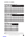
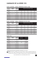
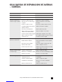
OUTPUTS 85 SERIES
ADJUSTABLE OUTPUT – APPROXIMATE GPD @ 60Hz
MODEL MAXIMUM PUMP TUBE FEED RATE CONTROL SETTING
PRESSURE NUMBER L12345678910
85MHP5* 100 psi (6.9 bar) #1 0.3 0.5 1.0 1.5 2.0 2.5 3.0 3.5 4.0 4.5 5.0
85M1 25 psi (1.7 bar)
85MHP17* 100 psi (6.9 bar) #2 0.8 1.7 3.4 5.1 6.8 8.5 10.2 11.9 13.6 15.3 17.0
85M2 25 psi (1.7 bar)
85MHP40* 100 psi (6.9 bar) #7 2.0 4.0 8.0 12.0 16.0 20.0 24.0 28.0 32.0 36.0 40.0
85M3 25 psi (1.7 bar) #3
85M4 25 psi (1.7 bar) #4 3.0 6.0 12.0 18.0 24.0 30.0 36.0 42.0 48.0 54.0 60.0
85M5 25 psi (1.7 bar) #5 4.3 8.5 17.0 25.5 34.0 42.5 51.0 59.5 68.0 76.5 85.0
MODEL MAXIMUM PUMP TUBE FEED RATE CONTROL SETTING
PRESSURE NUMBER L12345678910
85MHP5* 100 psi (6.9 bar) #1 0.9 1.5 3.0 4.5 6.1 7.6 9.1 10.6 12.1 13.6 15.1
85M1 25 psi (1.7 bar)
85MHP17* 100 psi (6.9 bar) #2 2.4 5.1 10.3 15.4 20.6 25.7 30.9 36.0 41.2 46.3 51.5
85M2 25 psi (1.7 bar)
85MHP40* 100 psi (6.9 bar) #7 6.1 12.1 24.2 36.3 48.5 60.6 76.7 84.8 96.9 109.0 121.1
85M3 25 psi (1.7 bar) #3
85M4 25 psi (1.7 bar) #4 9.1 18.2 36.3 54.5 76.7 90.8 109.0 127.2 145.3 163.5 181.7
85M5 25 psi (1.7 bar) #5 13.0 25.7 51.5 77.2 103.0 128.7 154.4 180.0 205.9 231.6 257.4
ADJUSTABLE OUTPUT – APPROXIMATE LPD @ 50Hz
FIXED OUTPUT
MODEL MAXIMUM PUMP TUBE GPD 60Hz LPD 50Hz
PRESSURE NUMBER
85MPHP5* 100 psi (6.9 bar) #1 5.0 15.1
85MP1 25 psi (1.7 bar)
85MPHP17* 100 psi (6.9 bar) #2 17.0 51.5
85MP2 25 psi (1.7 bar)
85MPHP40* 100 psi (6.9 bar) #7 40.0 121.1
85MP3 25 psi (1.7 bar) #3
85MP4 25 psi (1.7 bar) #4 60.0 181.7
85MP5 25 psi (1.7 bar) #5 85.0 257.4
NOTICE: The information within this chart is solely intended for use as a guide. The output data is an approximation based on
pumping water under a controlled testing environment. Many variables can affect the output of the pump. Stenner Pump
Company recommends that all metering pumps undergo field calibration by means of analytical testing to confirm their outputs.
*Injection check valve is included with pump rated 26-100 psi (1.8-6.9 bar).

www.stenner.com
10
ADJUSTABLE OUTPUT – APPROXIMATE GPD @ 60Hz
OUTPUTS 100 SERIES
MODEL MAXIMUM PUMP TUBE FEED RATE CONTROL SETTING
PRESSURE NUMBER L12345678910
100DMHP5* 100 psi (6.9 bar) #1 0.3 0.6 1.2 1.8 2.4 3.0 3.6 4.2 4.8 5.4 6.0
100DM1 25 psi (1.7 bar)
100DMHP20* 100 psi (6.9 bar) #2 1.0 2.0 4.0 6.0 8.0 10.0 12.0 14.0 16.0 18.0 20.0
100DM2 25 psi (1.7 bar)
100DM3 100 psi (6.9 bar) #3 2.2 4.4 8.8 13.2 17.6 22.0 26.4 30.8 35.2 39.6 44.0
100DM4 25 psi (1.7 bar) #4 3.5 7.0 14.0 21.0 28.0 35.0 42.0 49.0 56.0 63.0 70.0
100DM5 25 psi (1.7 bar) #5 5.0 10.0 20.0 30.0 40.0 50.0 60.0 70.0 80.0 90.0 100.0
MODEL MAXIMUM PUMP TUBE FEED RATE CONTROL SETTING
PRESSURE NUMBER L12345678910
100DMHP5* 100 psi (6.9 bar) #1 0.9 1.8 3.6 5.5 7.3 9.1 10.9 12.7 14.5 16.4 18.2
100DM1 25 psi (1.7 bar)
100DMHP20* 100 psi (6.9 bar) #2 3.0 6.1 12.1 18.2 24.2 30.3 36.4 42.4 48.5 54.5 60.6
100DM2 25 psi (1.7 bar)
100DM3 100 psi (6.9 bar) #3 6.7 13.3 26.7 40.0 53.3 66.6 79.9 93.3 106.6 119.9 133.2
100DM4 25 psi (1.7 bar) #4 10.6 21.2 42.4 63.6 84.8 106.0 127.2 148.4 169.6 190.8 212.0
100DM5 25 psi (1.7 bar) #5 15.1 30.3 60.6 90.8 121.1 151.4 181.7 212.0 242.2 272.5 302.8
ADJUSTABLE OUTPUT – APPROXIMATE LPD @ 50Hz
FIXED OUTPUT
MODEL MAXIMUM PUMP TUBE GPD 60Hz LPD 50Hz
PRESSURE NUMBER
100DMPHP5* 100 psi (6.9 bar) #1 6.0 18.2
100DMP1 25 psi (1.7 bar)
100DMPHP20*100 psi (6.9 bar) #2 20.0 60.6
100DMP2 25 psi (1.7 bar)
100DMP3 25 psi (1.7 bar) #3 44.0 133.2
100DMP4 25 psi (1.7 bar) #4 70.0 212.0
100DMP5 25 psi (1.7 bar) #5 100.0 302.8
NOTICE: The information within this chart is solely intended for use as a guide. The output data is an approximation based on
pumping water under a controlled testing environment. Many variables can affect the output of the pump. Stenner Pump
Company recommends that all metering pumps undergo field calibration by means of analytical testing to confirm their outputs.
*Injection check valve is included with pump rated 26-100 psi (1.8-6.9 bar).

USA and Canada 800.683.2378, International 904.641.1666 11
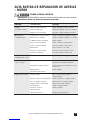
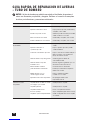
OUTPUTS 170 SERIES
ADJUSTABLE OUTPUT – APPROXIMATE GPD @ 60Hz
MODEL MAXIMUM PUMP TUBE FEED RATE CONTROL SETTING
PRESSURE NUMBER L12345678910
170DMHP9* 100 psi (6.9 bar) #1 0.5 1.0 2.0 3.0 4.0 5.0 6.0 7.0 8.0 9.0 10.0
170DM1 25 psi (1.7 bar)
170DMHP34* 100 psi (6.9 bar) #2 1.7 3.4 6.0 9.5 13.6 17.0 20.4 23.8 27.2 30.6 34.0
170DM2 25 psi (1.7 bar)
170DM3 25 psi (1.7 bar) #3 4.0 8.0 16.0 24.0 32.0 40.0 48.0 56.0 64.0 72.0 80.0
170DM4 25 psi (1.7 bar) #4 6.0 12.0 24.0 36.0 48.0 60.0 72.0 84.0 96.0 108.0 120.0
170DM5 25 psi (1.7 bar) #5 8.5 17.0 34.0 51.0 68.0 85.0 102.0 119.0 136.0 153.0 170.0
MODEL MAXIMUM PUMP TUBE FEED RATE CONTROL SETTING
PRESSURE NUMBER L12345678910
170DMHP9* 100 psi (6.9 bar) #1 1.5 3.0 6.1 9.1 12.1 15.1 18.2 21.2 24.2 27.3 30.3
170DM1 25 psi (1.7 bar)
170DMHP34* 100 psi (6.9 bar) #2 5.1 10.3 18.2 28.8 39.1 51.5 61.8 72.1 82.4 92.7 102.6
170DM2 25 psi (1.7 bar)
170DM3 25 psi (1.7 bar) #3 12.1 24.2 48.5 72.7 96.9 121.1 145.4 169.6 193.8 218.0 242.2
170DM4 25 psi (1.7 bar) #4 18.2 36.3 72.7 109.0 145.3 181.7 218.0 254.4 290.7 327.0 363.4
170DM5 25 psi (1.7 bar) #5 25.7 51.5 86.0 154.4 205.9 257.4 308.9 360.4 411.8 463.3 514.8
ADJUSTABLE OUTPUT – APPROXIMATE LPD @ 50Hz
FIXED OUTPUT
MODEL MAXIMUM PUMP TUBE GPD 60Hz LPD 50Hz
PRESSURE NUMBER
170DMPHP9* 100 psi (6.9 bar) #1 10.0 30.3
170DMP1 25 psi (1.7 bar)
170DMPHP34* 100 psi (6.9 bar) #2 34.0 102.6
170DMP2 25 psi (1.7 bar)
170DMP3 25 psi (1.7 bar) #3 80.0 242.2
170DMP4 25 psi (1.7 bar) #4 120.0 363.4
170DMP5 25 psi (1.7 bar) #5 170.0 514.8
NOTICE: The information within this chart is solely intended for use as a guide. The output data is an approximation based on
pumping water under a controlled testing environment. Many variables can affect the output of the pump. Stenner Pump
Company recommends that all metering pumps undergo field calibration by means of analytical testing to confirm their outputs.
*Injection check valve is included with pump rated 26-100 psi (1.8-6.9 bar).

www.stenner.com
12
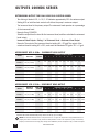
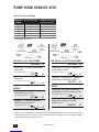
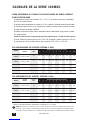
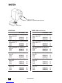
OUTPUTS 100MDC SERIES
DETERMINING OUTPUT FOR DUAL HEAD DUAL CONTROL MODEL
• The dial ring is labeled L-10; L = 5%, 1-10 indicates approximately 10% of maximum output.
• Setting #10 on both feed rate controls will deliver the pump’s maximum output.
• The innermost head is the primary output. The outermost head operates at a percentage
of the innermost head.
• Example Using 100MCD5
Select the output from the chart for the innermost head, and then calculate the outermost
head output.
Innermost Head Output x Setting % of Outermost Head = Outermost Head Output
Example: The output of the innermost head at setting #4 = 20 gpd. The output of the
outermost head at setting #3 is 30%; and would be calculated 20 gpd x 30% = 6 gpd.
APPROXIMATE GPD @ 60Hz – INNERMOST HEAD OUTPUT
MODEL MAXIMUM PUMP TUBE FEED RATE CONTROL SETTING
PRESSURE NUMBER L12345678910
100MDCHP5* 100 psi (6.9 bar) #1 0.2 0.3 0.6 0.9 1.2 1.5 1.8 2.1 2.4 2.7 3.0
100MDC1 25 psi (1.7 bar)
100MDCHP20* 100 psi (6.9 bar) #2 0.5 1.0 2.0 3.0 4.0 5.0 6.0 7.0 8.0 9.0 10.0
100MDC2 25 psi (1.7 bar)
100MDC3 25 psi (1.7 bar) #3 1.1 2.2 4.4 6.6 8.8 11.0 13.2 15.4 17.6 19.8 22.0
100MDC4 25 psi (1.7 bar) #4 1.7 3.5 7.0 10.5 14.0 17.5 21.0 24.5 28.0 31.5 35.0
100MDC5 25 psi (1.7 bar) #5 2.5 5.0 10.0 15.0 20.0 25.0 30.0 35.0 40.0 45.0 50.0
NOTICE: The information within this chart is solely intended for use as a guide. The output data is an approximation based on
pumping water under a controlled testing environment. Many variables can affect the output of the pump. Stenner Pump
Company recommends that all metering pumps undergo field calibration by means of analytical testing to confirm their outputs.
*Injection check valve included with pumps rated 26-100 psi (1.8-6.9 bar).
MODEL MAXIMUM PUMP TUBE FEED RATE CONTROL SETTING
PRESSURE NUMBER L12345678910
100MDCHP5* 100 psi (6.9 bar) #1 0.6 0.9 1.8 2.7 3.6 4.5 5.5 6.4 7.3 8.2 9.1
100MDC1 25 psi (1.7 bar)
100MDCHP20* 100 psi (6.9 bar) #2 1.5 3.0 6.1 9.1 12.1 15.1 18.2 21.2 24.2 27.3 30.3
100MDC2 25 psi (1.7 bar)
100MDC3 25 psi (1.7 bar) #3 3.3 6.6 13.3 20.0 26.6 33.3 40.0 46.6 53.3 60.0 66.6
100MDC4 25 psi (1.7 bar) #4 5.1 10.6 21.2 31.8 42.4 53.0 63.6 74.2 84.8 95.4 106.0
100MDC5 25 psi (1.7 bar) #5 7.6 15.1 30.3 45.4 60.6 75.7 90.8 106.0 121.1136.3 151.4
APPROXIMATE LPD @ 50Hz – INNERMOST HEAD OUTPUT

USA and Canada 800.683.2378, International 904.641.1666 13
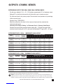
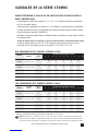
OUTPUTS 170MDC SERIES
DETERMINING OUTPUT FOR DUAL HEAD DUAL CONTROL MODEL
• The dial ring is labeled L-10; L = 5%, 1-10 indicates approximately 10% of maximum output.
• Setting #10 on both feed rate controls will deliver the pump’s maximum output.
• The innermost head is the primary output. The outermost head operates at a percentage
of the innermost head.
• Example Using 170MDCHP34
Select the output from the chart for the innermost head, and then calculate the
outermost head output.
Innermost Head Output x Setting % of Outermost Head = Outermost Head Output
Example: The output of the innermost head at setting #8 = 13.6 gpd. The output of the
outermost head at setting #6 is 60%; and would be calculated 13.6 gpd x 60% = 8.2 gpd.
APPROXIMATE GPD @ 60Hz – INNERMOST HEAD OUTPUT
MODEL MAXIMUM PUMP TUBE FEED RATE CONTROL SETTING
PRESSURE NUMBER L12345678910
170MDCHP9* 100 psi (6.9 bar) #1 0.3 0.5 1.0 1.5 2.0 2.5 3.0 3.5 4.0 4.5 5.0
170MDC1 25 psi (1.7 bar)
170MDCHP34*100 psi (6.9 bar) #2 0.8 1.7 3.4 5.1 6.8 8.5 10.2 11.9 13.6 15.3 17.0
170MDC2 25 psi (1.7 bar)
170MDC3 25 psi (1.7 bar) #3 2.0 4.0 8.0 12.0 16.0 20.0 24.0 28.0 32.0 36.0 40.0
170MDC4 25 psi (1.7 bar) #4 3.0 6.0 12.0 18.0 24.0 30.0 36.0 42.0 48.0 54.0 60.0
170MDC5 25 psi (1.7 bar) #5 4.3 8.5 17.0 25.5 34.0 42.5 51.0 59.5 68.0 76.5 85.0
MODEL MAXIMUM PUMP TUBE FEED RATE CONTROL SETTING
PRESSURE NUMBER L12345678910
170MDCHP9* 100 psi (6.9 bar) #1 0.9 1.5 3.0 4.5 6.1 7.6 9.1 10.6 12.1 13.6 15.1
170MDC1 25 psi (1.7 bar)
170MDCHP34* 100 psi (6.9 bar) #2 2.4 5.1 10.3 15.4 20.6 25.7 30.9 36.0 41.2 46.3 51.5
170MDC2 25 psi (1.7 bar)
170MDC3 25 psi (1.7 bar) #3 6.1 12.1 24.2 36.3 48.5 60.6 76.7 84.8 96.9 109.0 121.1
170MDC4 25 psi (1.7 bar) #4 9.1 18.2 36.3 54.5 76.7 90.8 109 127.2 145.3 163.5 181.7
170MDC5 25 psi (1.7 bar) #5 13.0 25.7 51.5 77.2 103.0 128.7 154.4 180.0 205.9 231.6 257.4
APPROXIMATE LPD @ 50Hz – INNERMOST HEAD OUTPUT
NOTICE: The information within this chart is solely intended for use as a guide. The output data is an approximation based on
pumping water under a controlled testing environment. Many variables can affect the output of the pump. Stenner Pump
Company recommends that all metering pumps undergo field calibration by means of analytical testing to confirm their outputs.
*Injection check valve included with pumps rated 26-100 psi (1.8-6.9 bar).

www.stenner.com
14
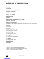
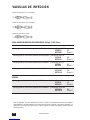
MATERIALS OF CONSTRUCTION
All Housings
Polycarbonate
Peristaltic Tube*& Check Valve Duckbill
Santoprene®, FDA approved
Peristaltic Tube**
Tygothane®, FDA approved
Check Valve Duckbill†
Pellathane®
Suction/Discharge Tubing & Ferrules (1/4" & 6 mm)
Polyethylene, FDA approved
Weighted Suction Line Strainer
Polypropylene or Type 1 Rigid PVC body with Type 1 Rigid PVC cap, NSF listed; ceramic weight
All Fasteners
Stainless Steel
Tube Fittings
Gray: Type 1 Rigid PVC, NSF listed
Black: Polypropylene, NSF listed
Check Valve Fittings
Type 1 Rigid PVC, NSF listed
Connecting Nuts
Type 1 Rigid PVC or Polypropylene
3/8" Adapter
Type 1 Rigid PVC, NSF listed
Pump Head Latches
Polypropylene
*Santoprene®is a registered trademark of Exxon Mobil Corporation.
** Tygothane®is a registered trademark of Saint-Gobain Performance Plastics.
†Pellathane®is a registered trademark of The Dow Company.

USA and Canada 800.683.2378, International 904.641.1666 15
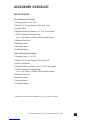
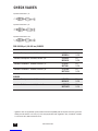
ACCESSORY CHECKLIST
PRE-INSTALLATION
25 psi Accessory Kit Contents*
3 Connecting Nuts 1/4" or 3/8"
3 Ferrules 1/4" & 6 mm Europe OR 2 Ferrules 3/8"
1 Injection Fitting
1 Weighted Suction Line Strainer 1/4", 3/8", 6 mm Europe
1 20' Roll of Suction/Discharge Tubing
1/4" or 3/8" White or UV Black OR 6 mm White Europe
1 Additional Pump Tube
2 Additional Latches
1 Mounting Bracket
1 Installation Manual
100 psi Accessory Kit Contents*
3 Connecting Nuts 1/4" or 3/8"
3 Ferrules 1/4" & 6 mm Europe OR 2 Ferrules 3/8"
1 Injection Check Valve
1 Weighted Suction Line Strainer 1/4" or 3/8", 6 mm Europe
1 20' Roll of Suction/Discharge Tubing
1/4" or 3/8" White or UV Black OR 6 mm White Europe
1 Additional Pump Tube
2 Additional Latches
1 Mounting Bracket
1 Installation Manual
*Double head pumps include an additional set of the accessories listed above.

www.stenner.com
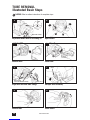
16
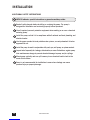
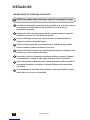
INSTALLATION
ADDITIONAL SAFETY INSTRUCTIONS
NOTICE: Indicates special instructions or general mandatory action.
Read all safety hazards before installing or servicing the pump. The pump is
designed for installation and service by properly trained personnel.
Use all required personal protective equipment when working on or near a chemical
metering pump.
Install the pump so that it is in compliance with all national and local plumbing and
electrical codes.
Use the proper product to treat potable water systems, use only chemicals listed or
approved for use.
Install the pump to work in conjunction with pool, spa, well pump, or system controls.
Inspect tube frequently for leakage, deterioration, or wear. Schedule a regular pump
tube maintenance change to prevent chemical damage to pump and/or spillage.
Mount pump vertically and use spill recovery to run chemical back to tank in the
event of tube failure.
Pump is not recommended for installation in areas where leakage can cause
personal injury or property damage.

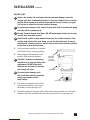
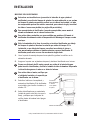
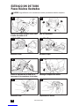
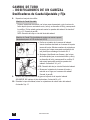
MOUNT PUMP
Select a dry location (to avoid water intrusion and pump damage) above the
solution tank. Best recommended location is above the solution tank in a vertical
position with the pump head pointed downward and the spill recovery (see page
20) in place to reduce the risk and severity of damage.
To prevent pump damage in the event of a pump tube leak, never mount the pump
vertically with the pump head up.
To avoid chemical damage from fumes, DO NOT mount pump directly over an open
solution tank. Keep tank covered.
Avoid flooded suction or pump mounted lower than the solution container. Draw
solution from the top of the tank. Pump can run dry without damage. If pump is
installed with a flooded suction, a shut-off valve or other device must be provided
to stop flow to pump during service.
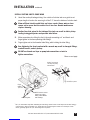
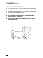
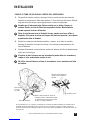
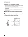
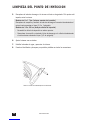
1. Use the mounting bracket as a template
to drill pilot holes in mounting location.
2. Secure bracket with fasteners or wall
anchors. Slide pump into bracket.
Provide 8" clearance to allow pump
orientation to be reversed during tube
replacement. DO NOT allow water
intrusion into the motor or corrosion
and damage will occur.
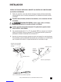
To prevent motor damage, verify
with a volt meter that the receptacle
voltage corresponds with the
pump voltage.
3. Plug cord into receptacle and turn the
motor power switch on. If the pump is
adjustable, turn the dial ring to 10.
4. Activate the pump by the pump control (flow switch, pressure switch, etc.) and verify
rotation of the roller assembly within the clear pump head. Turn pump switch off.
USA and Canada 800.683.2378, International 904.641.1666 17
INSTALLATION continued
Rain Roof
(optional)
slips into
wall bracket.
Wall Bracket
Pump Head

www.stenner.com
18
INSTALLATION continued
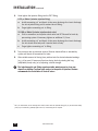
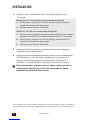
ADDITIONAL INSTRUCTIONS FOR CE PUMPS
ADDITIONAL INSTALLATION INSTRUCTIONS
1. All Class II Pumps located in Zone 1 of swimming pool areas require locating where flooding cannot occur.
2. This pump is intended to be installed as “fixed” as opposed to portable.
3. The Rain Roof must be installed and “vertical orientation” mounting of entire unit observed.
4. After installation, the power supply plug must be accessible during use.
5. This unit must be scrapped if the supply cord is damaged.
6. Observe and comply with all National Wiring Standards.
ZUSTAZLICHE INSTALLIERUNGSANWEISUNGUN
1. Pumpen die sich in Zone 1 vom Schwimmbecken befinden sollen sind so einzurichten daß
Ueberschwemmungen nicht vorkommen werden.
2. Diese Pumpe ist als fest montierte Ausrustung bedacht und soll nicht umstellbar gebraucht werden.
3. Der Regendach muss installiert werden. Eine vertikale Asrichtung der Montage muß erzielt werden.
4. Die Stromversorgung muss nach der Installierung noch zuganglich sein.
5. Bei beschadigter Verkabelung ist dieses Gerat nicht mehr zu gebrauchen.
6. Staatliche Vernetzungsvorchriften mussen eingehalten werden.
INSTRUCTIONS SUPPLÉMENTAIRES D’INSTALLTION
1. Toutes les pompes installées dans la Zone 1 du périmètre de la piscine doivent être situées de manière à
ne pas pouvoir être inondées.
2. Cette pompe est prévue pour installation fixe et non pas portative.
3. L’abri anti-pluie doit être installé et l’orientation verticale doit toujours être observée.
4. Après l’installation, la prise électrique doit rester accessible pendant l’utilisation.
5. Cette unité doit être mise au rebut si le cordon électrique est endommagé.
6. Observez et adhérez à toutes les Normes Nationales pour Installations Electriques.
INSTUCCIONES ADICIONALES PARA INSTALACIÓN
1. Todas las bombas Clase II situadas en la Zona 1 de las áreas de la piscina requieren colocarse donde no
puedan ser inundadas.
2. Esta bomba es para ser instalada “fija” en vez de portátil.
3. Es necesario instalar el techo de lluvia, y montar la unidad entera siguiendo una orientación vertical.
4. Depués de la instalación el enchufe suministrador de energía debe estar accesible durante el uso.
5. Se deberá deshechar la unidad si el cordón de abastecimiento se deteriora.
6. Observe y cumpla con todas las Reglas Nacionales para Instalaciones Eléctricas.
ISTRUZIONI SUPPLEMENTARI PER L’ INSTALLAZIONE
1. Tutte le pompe Classe II localizzate nella Zona 1 della superficie circostante la piscina devono essere
collocate dove gli allagamenti no possono accadere..
2. Questa pompa, é inteso, deve essere installata come ‘fissa’ e non come portatile.
3. La tettoia deve essere installata e il montaggio ‘orientazione verticale’ dell’intera unitá deve essere osservato.
4. Dopo l’installazione, la spina deve essere accessibile durante l’uso.
5. Questa unitá deve essere gettata via se il filo elettrico é danneggiato.
6. Osservare e aderire a tutte le Norme Nazionali Sugli Impianti Elettrici.

USA and Canada 800.683.2378, International 904.641.1666 19
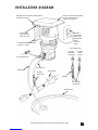
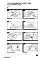
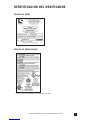
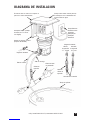
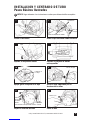
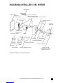
INSTALLATION DIAGRAM
Rain Roof slides into wall mounting bracket
(no tools necessary).
On/Off Switch
(under roof, not
visible this view)
Vertical Wall Mounting Bracket
(requires 2 screws)
Injection
Check Valve
Discharge Line
Disassembled View
Suction Line
Solution Tank
Shut-Off Valve
Duckbill
Injection
Fitting
0-25 psi
Injection
Check Valve
26-100 psi
Grounded
Power Outlet;
protected by
Ground-Fault
Circuit-
Interrupter
(GFCI)
Always use Rain Roof for outdoor
use or if metering pump is
subject to washdowns.
Flow direction
of solution.
Disassembled View

20
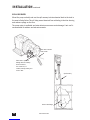
INSTALLATION continued
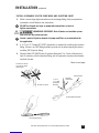
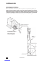
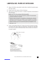
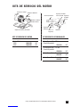
SPILL RECOVERY
Mount the pump vertically and use the spill recovery to drain chemical back to the tank in
the event of tube failure. This will help prevent chemical from collecting in the tube housing
and reduces spillage on the floor.
The pump motor is ventilated and water intrusion can cause motor damage. A rain roof is
recommended for outdoor and wet environments.
Strainer with Weight
Spill Recovery
3"
www.stenner.com
Tube drains solution
back to tank.
Partial hole is punched
through with a #2 Phillips
head screwdriver.
Use section of 1/4"
suction/discharge tubing and
insert in hole.
A página está carregando...
A página está carregando...
A página está carregando...
A página está carregando...
A página está carregando...
A página está carregando...
A página está carregando...
A página está carregando...
A página está carregando...
A página está carregando...
A página está carregando...
A página está carregando...
A página está carregando...
A página está carregando...
A página está carregando...
A página está carregando...
A página está carregando...
A página está carregando...
A página está carregando...
A página está carregando...
A página está carregando...
A página está carregando...
A página está carregando...
A página está carregando...
A página está carregando...
A página está carregando...
A página está carregando...
A página está carregando...
A página está carregando...
A página está carregando...
A página está carregando...
A página está carregando...
A página está carregando...
A página está carregando...
A página está carregando...
A página está carregando...
A página está carregando...
A página está carregando...
A página está carregando...
A página está carregando...
A página está carregando...
A página está carregando...
A página está carregando...
A página está carregando...
A página está carregando...
A página está carregando...
A página está carregando...
A página está carregando...
A página está carregando...
A página está carregando...
A página está carregando...
A página está carregando...
A página está carregando...
A página está carregando...
A página está carregando...
A página está carregando...
A página está carregando...
A página está carregando...
A página está carregando...
A página está carregando...
A página está carregando...
A página está carregando...
A página está carregando...
A página está carregando...
A página está carregando...
A página está carregando...
A página está carregando...
A página está carregando...
A página está carregando...
A página está carregando...
A página está carregando...
A página está carregando...
A página está carregando...
A página está carregando...
A página está carregando...
A página está carregando...
A página está carregando...
A página está carregando...
A página está carregando...
A página está carregando...
-
 1
1
-
 2
2
-
 3
3
-
 4
4
-
 5
5
-
 6
6
-
 7
7
-
 8
8
-
 9
9
-
 10
10
-
 11
11
-
 12
12
-
 13
13
-
 14
14
-
 15
15
-
 16
16
-
 17
17
-
 18
18
-
 19
19
-
 20
20
-
 21
21
-
 22
22
-
 23
23
-
 24
24
-
 25
25
-
 26
26
-
 27
27
-
 28
28
-
 29
29
-
 30
30
-
 31
31
-
 32
32
-
 33
33
-
 34
34
-
 35
35
-
 36
36
-
 37
37
-
 38
38
-
 39
39
-
 40
40
-
 41
41
-
 42
42
-
 43
43
-
 44
44
-
 45
45
-
 46
46
-
 47
47
-
 48
48
-
 49
49
-
 50
50
-
 51
51
-
 52
52
-
 53
53
-
 54
54
-
 55
55
-
 56
56
-
 57
57
-
 58
58
-
 59
59
-
 60
60
-
 61
61
-
 62
62
-
 63
63
-
 64
64
-
 65
65
-
 66
66
-
 67
67
-
 68
68
-
 69
69
-
 70
70
-
 71
71
-
 72
72
-
 73
73
-
 74
74
-
 75
75
-
 76
76
-
 77
77
-
 78
78
-
 79
79
-
 80
80
-
 81
81
-
 82
82
-
 83
83
-
 84
84
-
 85
85
-
 86
86
-
 87
87
-
 88
88
-
 89
89
-
 90
90
-
 91
91
-
 92
92
-
 93
93
-
 94
94
-
 95
95
-
 96
96
-
 97
97
-
 98
98
-
 99
99
-
 100
100


Stenner Pumps 100DM5 Installation and Maintenance Manual
- Tipo
- Installation and Maintenance Manual
- Este manual também é adequado para
em outras línguas
- español: Stenner Pumps 100DM5
- English: Stenner Pumps 100DM5
Outros documentos
-
Bushnell 78-8890 Manual do usuário
-
Tasco Spacestation 49076525/49114675 Manual do usuário
-
Bushnell 78-8845 Manual do usuário
-
Bushnell 78-8831, 78-8846 Manual do usuário
-
Bushnell Discoverer - 788970, 788930, 788945 Manual do usuário
-
ESAB m2™ Plasma Smart Plasmarc™ 200 Cutting System Manual do usuário
-
ESAB PT-37 Plasmarc Cutting Torches Manual do usuário
-
Velleman AFMHP Manual do usuário
-
-
dosatron D25 Manual do proprietário