Mettler Toledo Transmitter M400 Instruções de operação
- Tipo
- Instruções de operação


© 02/2023 METTLERTOLEDO.
Subjecttotechnicalchanges.PrintedinSwitzerland.52 121 395 I

3
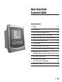
Quick Setup Guide
Transmitter M400
Content
1 Operation 4
2 Menu Structure 5
3 TerminalBlock(TB)denitions 6
4 Wiring example for pH Transmitter 9
5 General Setup (applies for all parameters) 10
6 pHCalibrationincl.ISFET 11
7 O2 Calibration 13
8 CO2 Calibration (InPro 5000) 14
9 CO2 Hi (High) Calibration (InPro 5500 i) 17
10 M400 Type 1 Cond Ind only:
Conductivity Calibration for inductive Sensors 19
11 Conductivity Quick Setup 20
12 Conductivity Calibration
for 2-e and 4-e Sensors 21
13 TDLGPro™500 22
14 Environmentalprotection 26
English
en

4
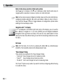
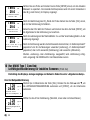
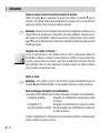
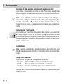
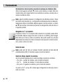
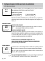
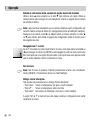
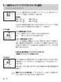
1 Operation
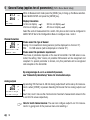
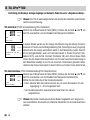
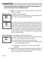
Entry of data values, selection of data entry options
Use the m key to increase or the . key to decrease a digit. Use the same keys to
navigatewithinaselectionofvaluesoroptionsofadataentryeld.
h Note:Somescreensrequireconguringmultiplevaluesviathesamedataeld(ex:
conguringmultiplesetpoints).Besuretousethec or b key to return to the pri-
maryeldandthem or .keytotogglebetweenallcongurationoptionsbefore
entering to the next display screen.
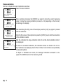
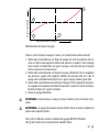
Navigation with u in Display
If a u is displayed on the bottom right hand corner of the display, you can use the
c or bkey tonavigate toit.Ifyou click[ENTER] youwill navigatebackwards
through the menu (go back one screen). This can be a very useful option to move
back up the menu tree without having to exit into the measuring mode and re-enter
the menu.
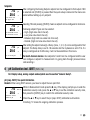
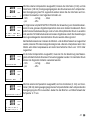
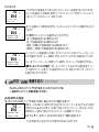
Exit menu
h Note: Exit the menu at any time by pressing the b and c key simultaneously
(ESCAPE). The transmitter returns to the Measurement mode.
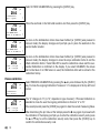
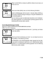
”Save changes” dialog
Three options are possible for the ”Save changes” dialog:
– ”Yes & Exit”: Save changes and exit to measuring mode.
– ”Yes & u”: Save changes and go back one screen.
–”No&Exit”: Don’tsavechangesandexittomeasuringmode.
The ”Yes & u”optionisveryusefulifyouwanttocontinueconguringwithouthaving
to re-enter the menu.
en

5
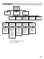
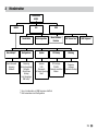
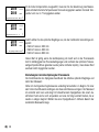
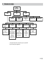
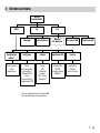
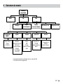
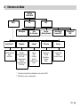
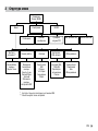
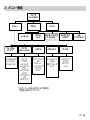
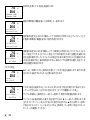
2 Menu Structure
Channel Select
Output
Set Points
Measurement
Mode M400
CalMenu Info
Quick Setup** Configure System PID Setup Service
Messages Calibration Data ISM Sensor Info* ISM Diagnostics*
Measurement
Analog Outputs
Set Points
Alarm/Clean
Display
Hold outputs
ISM Setup*
Set Language
USB
Passwords
Set/Clear Lockout
Reset
PID Display
PID/AM
Tune Parameters
Mode
Diagnostics
Calibrate
Tech Service
Model/Software
Revision
* Only available in combination with ISM sensors.
** Do not use after configuration
en

6
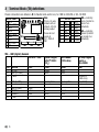
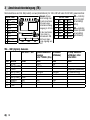
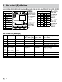
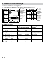
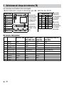
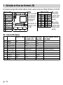
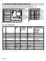
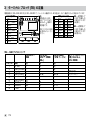
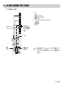
3 Terminal Block (TB) denitions
Power connections are labeled – N for Neutral and + LforLine,for100to240VACor20–30VDC.
TB2 for 2
1AO1+
2AO1–/AO2–
3AO2+
4AO3+
5AO3–/AO4–
6 AO4+
7DI1+
8DI1–/DI2–
9DI2+
TB2 for 2
1NO1 8 NC5
2COM1 9 COM6
3 NC1 10 NO6
4NO2 11 NO3
5COM2 12 COM3
6NC2 13 NO4
7COM5 14 COM4
TB2 TB3 TB4
TB1 1 14
1 9 1 9 1 9
Note:
This is a 4-wire-
product with an
active 4–20 mA
analog output.
Please do not
supply to
Pin1–Pin6of
TB2.
NO = normally
open (contact is
open if un-
actuated).
NC = normally
closed (contact
is closed if un-
actuated).
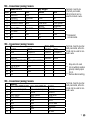
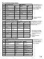
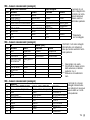
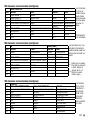
TB4 – ISM (digital) Sensors
TDL GPro™ 500 Optical Oxygen,
InPro™ 5500 i
(CO2)
InPro 6860 i
(VP8 cable) pH, amp. Oxygen,
Cond 4-e,
InPro 5000 i
Term. Function Color Color Color Color
124VDC – brown grey –
2GND(24VDC) – black blue –
3 1-Wire – – – transparent
(cable core)
4GND(5VDC) –green / yellow green / yellow red (shield)
5 – – – – –
6 GND(5VDC) brown – – –
7RS485-B yellow blue brown –
8RS485-A green white pink –
95VDC – – – –
en

7
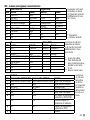
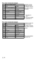
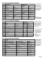
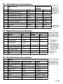
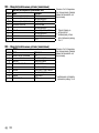
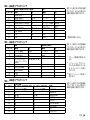
TB3 – Conventional (analog) Sensors
Cond 2-E or 4-E amp. Oxygen
Term. Function Color* Function Color
1 Cnd inner1 white – –
2 Cnd outer1 white / blue Anode red
3 Cnd inner2 blue – –
4Cnd outer2 / Shield black Shield/GND green / yellow
5 – – Cathode transparent
6 RTDret/GND bare shield GND/NTC green
7RTDsense red – –
8RTD green NTC white
9+5V –+5V –
Terminal4and6are
internally connected,
either terminal can be
used to connect a wire.
* Transparent
not connected.
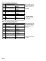
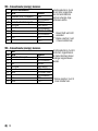
TB3 – Conventional (analog) Sensors
pH Redox (ORP)
Term. Function Color* Function Color
1 Glass tansparent Platinum transparent***
2 – – – –
3Reference** red Reference Shield
4SolutionGND/Shield** green / yellow and blue – –
5 – – – –
6 RTDret/GND white – –
7RTDsense – – –
8RTD green – –
9+5V – – –
Terminal4and6areinter-
nally connected, either ter-
minal can be used to con-
nect a wire.
* Grey wire not used.
** ForpHwithoutsolution
ground, install jumper
3 to 4.
***Removeblackcoating.
Terminal4and6areinter-
nally connected, either ter-
minal can be used to con-
nect a wire.
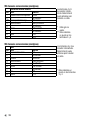
TB3 – Conventional (analog) Sensors
Cond Ind
Term. Color. InPro 7250 ST / PFA Color. InPro 7250 HT Function
1Coax inner / transparent Coax inner / transparent receive hi
2 red yellow receive lo
3green / yellow green / yellow shield/GND
4 brown, white violet send lo
5 blue black send hi
6white white RTDret/GND
7 grey grey RTDsense
8 green green RTD
9 – – not used
en

8
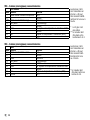
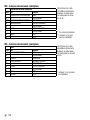
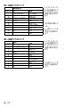
TB3 – Conventional (analog) Sensors
ISFET
Term. Color Function
1 Coax inner / pink FET
2 – not used
3* yellow Reference
4* green / yellow GND/Shield
5 – not used
6 white RTDret/GND
7 – not used
8 grey RTD
9 brown +5V
Terminal4and6areinter-
nally connected, either ter-
minal can be used to con-
nect a wire.
* Jumper 3 to 4 has to be
installed.
TB3 – Conventional (analog) Sensors
Dissolved carbon dioxide
Term. Color* Function
1 Coax inner / transparent Glass
2 – not used
3** Coax shield / red Reference
4** green / yellow GND/Shield
5 – not used
6 white RTDret/GND
7 – not used
8 green RTD
9 – +5V
Terminal4and6areinter-
nally connected, either ter-
minal can be used to con-
nect a wire.
* Grey wire not used.
** Jumper 3 to 4 has to
be installed.
en

9
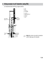
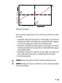
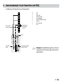
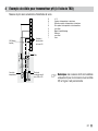
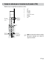
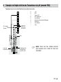
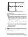
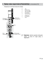
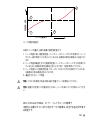
4 Wiring example for pH Transmitter (using TB3)
pH measurement with monitoring of glass electrode.
h Note: Wire colors only valid for connec tion
with VP cable, grey not connected.
1
2
3
4
5
6
7
8
9
yellowgreen
green
red
transparent
white
Combination
pH electrode
with RTD
and SG
Temperature
probe
blue
Cable
SG (Solution
Ground)
Jumper if
pH electrode
without SG
9 +5V
8 RTD
7 RTD sense
6 RTD ret/GND
5 not used
4 Solution GND/Shield
3 Reference
2 not used
1 Glass
en

10
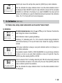
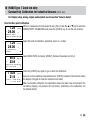
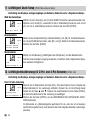
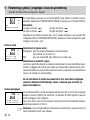
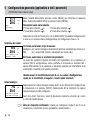
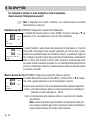
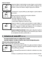
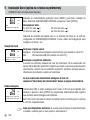
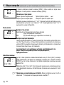
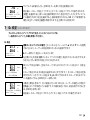
5 General Setup (applies for all parameters) (PATH: Menu / Quick Setup)
WhileinMeasurementmodepressthe[MENU]keytobringuptheMenuselection.
Select QUICK SETUPandpressthe[ENTER]key.
Display Convention:
1st line on display a 3rd line on display c
2nd line on display b 4th line on display d
Selecttheunitsofmeasurementforaandb.Onlylinesaandbcanbeconguredin
QUICK SETUP.GototheCongurationMenutocongurelinescandd.
Channel Selection
Please select the type of Sensor:
Analog: Forconventionalanalogsensors(willbedisplayedonchannel”A”).
ISM: ForISMsensors(willbedisplayedonchannel”B”).
Please select the parameter requirement:
The choice of parameter depends on the level of transmitter. If an ISM sensor is se-
lected,thesetting”Auto”means,allpossibleISMsensorswillberecognizedand
accepted.Ifaspecialparameterischosen,onlythisparameterwillberecognized
and accepted on the transmitter.
By using analogue 2-e or 4-e conductivity sensors,
see ”Conductivity Quick Setup” below for intermediate steps.
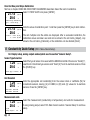
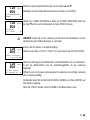
Analog out puts
By selecting YES the linear 4–20 mA analog output Aout1 will be set up for measure-
mentawhen[ENTER]ispressed.SelectingNO means that no analog output is set
up.
Aout1 min, Aout1 max are the minimum and maximum measurement values for the
4 and 20 mA values respectively.
h Note for multi channel devices:TheusercancongureoutputAout3tomesure-
ment c by going back to the previous menu and selecting c.
21.7 %sat
25.0 °C
MENU
Quick Setup
A 6.0 pH
A 25.0 °C
Channel Select = ISM
Parameter = Auto
7.0 pH
25.0 °C
Aout1 min= 0.000 pH
Aout1 max= 14.00 pH u
en

11
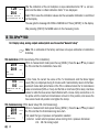
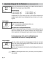
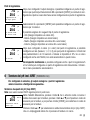
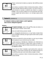
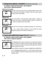
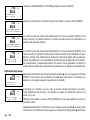
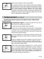
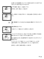
Setpoints
AfterconguringtheAnalogOutputasetpointcanbeconguredforthatoutput.IfNO
isselectedand[ENTER]ispressedthenthequicksetupisdoneandthemenusare
exited without setting up any setpoint.
Selecting YESandpressing[ENTER]meansasetpointcanbeconguredforchannela.
FollowingsetpointTypescanbeselected:
– High (High value has to be set).
– Low (Low value has to be set).
– Between (High and Low value has to be set).
–Outside(HighandLowvaluehastobeset).
Aftersettingthesetpointvalue(s)aRelay(none,1,2,3,4)canbeconguredforthat
setpoint.TheRelaydelayissetto10secondsandtheHysteresisissetto5%.Ifa
relayisconguredasCLEAN relay, it will not be selectable in this menu.
For multi-channel devices:Alsosetpoints5and6canbeconguredandtheuser
cancongureasetpointtomeasurementcbygoingbackthourghpreviousmenus
and selecting c.
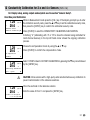
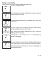
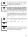
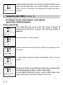
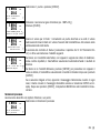
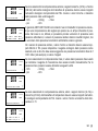
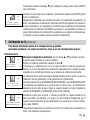
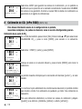
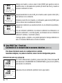
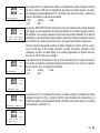
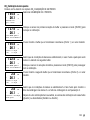
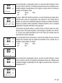
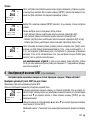
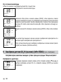
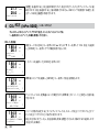
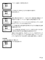
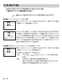
6 pH Calibration incl. ISFET (PATH: Cal)
For Display setup, analog outputs and setpoints see the section ”General Setup”.
pH (resp. ISFET) Two point Calibration
Remark:WhenusingISFETsensors,youhavetoadjustthezeropointrst.
While in Measurement mode press the c key. If the display prompts you to enter the
calibration security code, press the m or . key to set the calibration security code,
thenpressthe[ENTER]keytoconrmthecalibrationsecuritycode.
Press the m or .keytoselectthepH(resp.ISFET)calibrationsubfunction.
Aashing”H”showstheongoingcalibrationprocess.
7.0 pH
25.0 °C
a Set Point Yes
SP1 Type= Off u
7.0 pH
25.0 °C
SP1 BetweenH= 0.000
SP1 BetweenL= 0.000 u
7.0 pH
25.0 °C
SP1 use Relay #1 u
A 7.0 MΩ-cm
A 25.0 °C
Calibrate Sensor
Channel A pH m
en

12
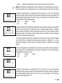
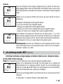
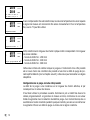
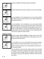
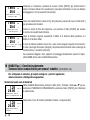
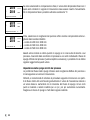
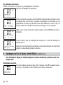
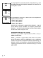
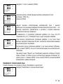
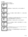
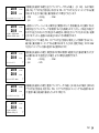
Select 2POINTCALIBRATIONbypressingthe[ENTER]key.
Placetheelectrodeintherstbuffersolutionandthenpressthe[ENTER]key.
Assoonasthestabilisationcriteriahavebeenfullled(or[ENTER]waspressedin
manual mode) the display changes and prompts you to place the electrode in the
second buffer solution.
Assoonasthestabilisationcriteriahavebeenfullled(or[ENTER]waspressedin
manual mode) the display changes to show the slope calibration factor S and the
offset calibration factor Z. Select ADJUST to save the calibration values and the suc-
cessfulCalibrationisconrmedonthedisplay.IfyouselectCALIBRATE, the values
will not be taken. If an ISM Sensor is used, the Calibration data will be stored in the
calibration history.
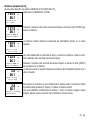
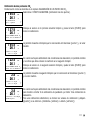
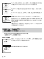
Process calibration
Select PROCESSCALIBRATION by pressing the mkeyoncefollowedbythe[ENTER]
key. To show the ongoing Calibration Process an ”H” is displayed in the top left hand
corner.
The ”H” changes to ”A” (or ”B”, depends on type of sensor) if Process Calibration is
selected to show the user the ongoing calibration on Channel ”A” or ”B”.
Takeasampleandpressthe[ENTER]keyagaintostorethecurrentmeasuringValue.
After determining the pH Value of the Sample press the c key again to proceed with
the calibration. If the display prompts you to enter the calibration security code, press
the m or .keytosetthecalibrationsecuritycode,thenpressthe[ENTER]keyto
conrmthecalibrationsecuritycode.
H 7.0 pH
25.0 °C
pH Calibration
Type = 2 point u
H 7.0 pH
25.0 °C
Press ENTER when
Sensor is in Buffer 1 u
H 7.0 pH
25.0 °C
Press ENTER when
Sensor is in Buffer 2 u
H 7.0 pH
25.0 °C
Point2 = 6.86 pH
pH = 7.00 pH u
H 7.0 pH
25.0 °C
pH Calibration
Type = Process u
A 7.0 pH
25.0 °C
Point1 = 7.00 pH
pH = 6.87 pH u
en

13
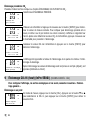
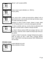
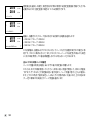
EnterthepHvalueofthesamplethenpressthe[ENTER]keytostartcalibration.
After the calibration the slope calibration factor S and the offset calibration factor Z
are displayed. Select ADJUST to save the new calibration values and the successful
Calibrationisconrmedonthedisplay.IfyouselectCALIBRATE, the values will not
be taken. If an ISM Sensor is used, the Calibration data will be stored in the calibration
history. The ”A” in the top left hand corner disappears.
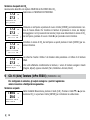
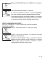
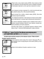
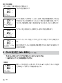
7 O2 Calibration (PATH: Cal)
For Display setup, analog outputs and setpoints see the section ”General Setup”.
O2 Calibration
For multi-channel devices: Using the m and .keyonthe”ChannelA”eldletsthe
user change the channel to be calibrated.
Enter Calibration mode by pressing the c key.
Aashing”H”(alternatingwith”A”or”B”toshowthechannelbeingcalibratedfor
multi- channel devices) in the top left hand corner shows the ongoing calibration
process.
ADOsensorcalibrationisalwaysaonepointcalibrationeitherinAir(Slope)ora
zero(Offset)calibration.
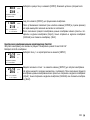
It is possible to select a SLOPE or ZEROCALIBRATION. A one point slope calibration
isdoneinair andaonepoint offsetcalibrationisdoneat 0ppbDO.Pressthe
[ENTER]keyafterselectingSLOPE or OFFSET.
EnterthevalueforPoint1includingadecimalpoint.DOisthevaluebeingmeasured
bythetransmitterandsensorintheunitssetbytheuser.Press[ENTER]whenthis
value is stable to perform the calibration.
After the calibration the slope calibration factor S and the offset calibration factor Z
are displayed.
A 7.0 pH
25.0 °C
pH S=100.0 % Z=7.124
Save Calibration Yes u
A 21.7 pH
A 25.0 °C
Calibrate Sensor
Channel B Oxygen m
H 21.7 %sat
25.0 °C
Point1 = 100.0 %sat
DO = 0.033 %sat u
H 21.7 %sat
25.0 °C
O2 S=0.019nA Z=0.000nA
Save Calibration Yes u
en

14
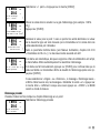
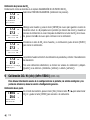
SelectADJUSTtosavethecalibrationvaluesandthesuccessfulcalibrationiscon-
rmedonthedisplay.IfyouselectCALIBRATE, the values will not be taken. If an ISM
Sensor is used, the Calibration data will be stored in the calibration history.
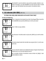
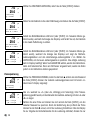
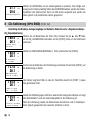
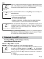
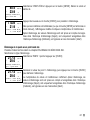
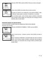
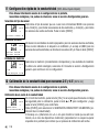
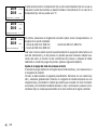
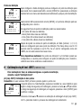
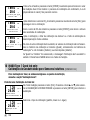
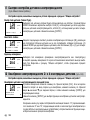
8 CO2 Calibration (InPro 5000) (PATH: Cal)
For Display setup, analog outputs and setpoints see the section ”General Setup”.
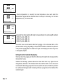
CO2 One point Calibration
Whileinmeasurementmodepressthekey[CAL].Pressthem or . key to select the
CO2CALIBRATIONandpressthe[ENTER]keytocallthesubfunction.
Select 1POINTandpress[ENTER].
Placethesensorinthebuffersolutionandpressthe[ENTER]keytostartthecalibra-
tion.
Thedisplayshowsthebufferthetransmitterhasrecognized(Point1)andthemea-
sured value.
Assoonasthedriftconditionshavestabilizedthedisplaychangestoshowtheslope
calibration factor S and the offset calibration factor Z.
After a successful calibration, the calibration values are taken over (Adjust) or were
aborted (Calibrate or Abort).
H 21.7 %sat
25.0 °C
Calibration Successful
A 180.4 hPa
A 26.1 °C
Calibrate Sensor
Channel A CO2 u
H 180.4 hPa
A 26.1 °C
CO2 Calibration
Type = 1 Point u
H 137.5 hPa
A 26.1 °C
Press ENTER when
Sensor is in Buffer 1 u
154.5 hPa
A 26.1 °C
A Point1 = 7.00 pH
A CO2 = 7.07 pH u
H 154.5 hPa
A 26.1 °C
pH S=100.0% Z=7.048pH
Save Adjust u
en

15
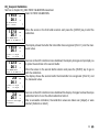
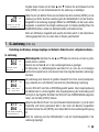
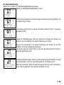
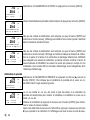
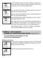
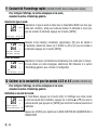
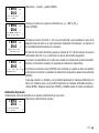
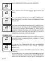
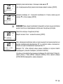
CO2 Two point Calibration
StartasinchapterCO2 ONEPOINTCALIBRATION described.
Select 2POINTCALIBRATION.
Placethesensorintherstbuffersolutionandpressthe[ENTER]keytostartthe
calibration.
Thedisplayshowsthebufferthetransmitterhasrecognized(Point1)andthemea-
sured value.
Assoonasthedriftconditionshavestabilized,thedisplaychangesandpromptsyou
to place the electrode in the second buffer.
Placethesensorinthesecondbuffersolutionandpressthe[ENTER]keytogoon
with the calibration.
Thedisplayshowsthesecondbufferthetransmitterhasrecognized(Point2)and
the measured value.
Assoonasthedriftconditionshavestabilizedthedisplaychangestoshowtheslope
calibration factor S and the offset calibration factor Z.
After a successful calibration, the calibration values are taken over (Adjust) or were
aborted (Calibrate or Abort).
A 154.5 hPa
A 26.1 °C
CO2 Calibration
Type = 2 Point u
H 137.5 hPa
A 26.1 °C
Press ENTER when
Sensor is in Buffer 1 u
154.5 hPa
A 26.1 °C
A Point1 = 7.00 pH
A CO2 = 7.07 pH u
122.4 hPa
A 26.1 °C
Press ENTER when
Sensor is in Buffer 2 u
2.8 hPa
A 26.1 °C
A Point2 = 9.21 pH ...
A CO2 = 8.80 pH u
2.8 hPa
A 26.1 °C
pH S=74.21% Z=6.948pH
Save Adjust u
en

16
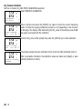
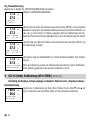
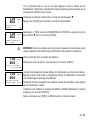
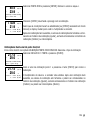
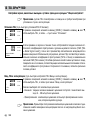
CO2 Process Calibration
StartasinchapterCO2 ONEPOINTCALIBRATION described.
Select PROCESSCALIBRATION.
Takea sampleandpress the[ENTER]key againto storethecurrent measuring
value. To show the ongoing calibration process, A or B (depending on the channel)
isblinkinginthedisplay.AfterdeterminingtheCO2 value of the sample, press the c
key again to proceed with the calibration.
EntertheCO2valueofthesamplethenpressthe[ENTER]keytostartcalibration.
The display shows the slope calibration factor S and the offset calibration factor Z.
After a successful calibration, the calibration values are taken over (Adjust) or were
aborted (Calibrate or Abort).
A 17.3 hPa
A 27.3 °C
CO2 Calibration
Type = Process u
A 17.3 hPa
A 27.3 °C
A Point1 = 00000 hPa
A CO2 = 17.3 hPa u
A 17.3 hPa
A 27.3 °C
A Point1 = 16.90 hPa
A CO2 = 17.3 hPa u
A 17.3 hPa
A 27.3 °C
pH S=100.0% Z=7.009pH
Save Adjust u
en

17
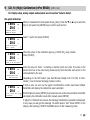
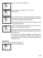
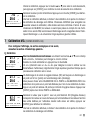
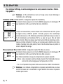
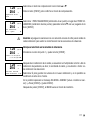
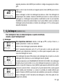
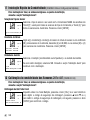
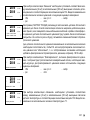
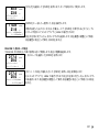
9 CO2 Hi (High) Calibration (InPro 5500 i) (PATH: Cal)
For Display setup, analog outputs and setpoints see the section ”General Setup”.
One point calibration
Whileinmeasurementmodepressthekey[CAL].Pressthe. or m key to select the
CO2Hiandpressthe[ENTER]keytocallthesubfunction.
Select“1point”andpress[ENTER].
Placethesensorinthecalibrationgas(e.g.100%CO2) resp. solution.
Press[ENTER].
Enter the value for Point 1 including a decimal point and units. The value in the
second text line is the value being measured by the transmitter and sensor in the
units selected by the user.
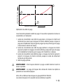
DependingontheDriftcontrol(seeUserManualchapter8.2.3.10“CO2 Hi Para-
meters”), one of the two following modes is active.
If Drift is auto, as soon as the signal of stabilization criteria have been fullled,
transmitter will display the calibration result automatic.
IfDriftisManual,press[ENTER]toproceedassoonasthevalueisstable,transmitter
willdisplaythecalibrationresultaftermanualpress[ENTER]
If ”Adjust” or ”Calibrate” are chosen, the message ”Calibration successful” is displayed.
Inanycaseyouwillgetthemessage”Re-installsensor”and”PressENTER”onthe
display.Afterpressing”ENTER”theM400returnstothemeasuringmode.
B 189.0 hPa
B 25.0 °C
Calibrate Sensor
Channel B CO2 Hi u
B 189.0 hPa
H 25.0 °C
CO2 Hi Calibration
Type = 1 Point u
B 189.0 hPa
H 25.0 °C
Press ENTER when
Sensor is in Gas (CO2) u
B 189.0 hPa
H 25.0 °C
B Point1=1013. hPa .
B CO2=189.0 hPa u
B 189.0 hPa
H 25.0 °C
CO2 S= 9.28 mV BL= 253 mV
Save Adjust u
en

18
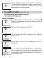
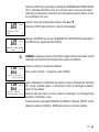
Process calibration
StartasinchapterOnepointCalibrationdescribed.
Select Process Calibration
Takea sampleandpress the[ENTER]key againto storethecurrent measuring
value. To show the ongoing calibration process, A or B (depending on the channel)
is blinking in the display.
AfterdeterminingtheCO2valueofthesamplepressthe[CAL]keyagaintoproceed
with the calibration.
EntertheCO2valueofthesamplethenpressthe[ENTER]keytostartthecalculation
of the calibration results.
After the calibration the slope calibration factor S and the offset calibration factor Z
are displayed.
In case of a successful calibration, the calibration values are stored in the cal his-
tory* and taken over (Adjust), stored in the cal history* and not taken over (Calibrate)
or discarded (Abort).
If ”Adjust” or ”Calibrate” are chosen, the message ”Calibration successful” is dis-
played. The M400 returns to the measuring mode.
B 189.0 hPa
H 25.0 °C
CO2 Hi Calibration
Type Process u
B 189.0 hPa
B 25.0 °C
Press ENTER to Capture
B CO2=189.0 hPa u
B 189.0 hPa
H 25.0 °C
B Point1=1013. hPa
B CO2=189.0 hPa u
B 189.0 hPa
H 25.0 °C
CO2 S= 9.28 mV BL= 253 mV
Save Adjust u
en

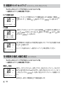
19
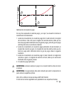
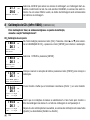
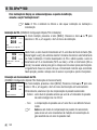
10 M400 Type 1 Cond Ind only:
Conductivity Calibration for inductive Sensors (PATH: Cal)
For Display setup, analog outputs and setpoints see the section ”General Setup”.
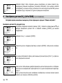
Cond Ind Zero point Calibration
Whileinmeasurementmodepressthekey[CAL].Pressthem or . key to select the
CONDUCTIVITYCALIBRATIONandpressthe[ENTER]keytocallthesubfunction.
Select the kind of calibration (standard, linear or n. water).
Select ZEROPOINTandpress[ENTER].Removethesensoranddryit.
Pressthe[ENTER]keyagaintogoonwiththecalibration.
Assoonastheconditionshavestabilized(or[ENTER]pressedinthemanualmode)
the display changes to show the multiplier and adder.
After a successful calibration, the calibration values are taken over and stored in the
cal history (Adjust), only stored in the cal history (Calibrate) or the calibration can
be aborted (Abort).
A 1.25 µS/cm
A 25.00 °C
Calibrate Sensor
Channel A Conductivity m
A 1.25 µS/cm
A 25.00 °C
Cal Compensation
Standard m
H 40.5 mS/cm
A 23.9 °C
Conductivity Calibration
Type = Zero Point u
A 1.035 mS/cm
A 21.9 °C
A Point 1 = 0.000 mS/cm
A C = 1.035 mS/cm u
en

20
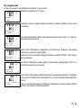
Cond Ind One point Slope Calibration
Start as in chapter CONDINDZEROPOINTCALIBRATION described. Select the kind of calib ration.
Select 1POINTSLOPEandpress[ENTER].
Enterthevalueofcalibrationpoint1andthenpressthe[ENTER]keytostartcalibra-
tion.
The cell multiplier and the adder are displayed. After a successful calibration, the
calibration values are taken over and can be stored in the cal history (Adjust), only
stored in the cal history (Calibrate) or the calibration can be aborted (Abort).
11 Conductivity Quick Setup (PATH: Menu / Quick Setup)
For Display setup, analog outputs and setpoints see the section ”General Setup”.
Sensor Type Selection
Select the type of sensor to be used with the M400 transmitter. Choices are ”Cond(2)”,
used for all 2-Electrode type sensors and ”Cond (4)” for all 4-electrode sensors. Press
the[ENTER]key.
Cell Constant
Enterthe appropriate cell constant(s):from thesensor label or certicate(M) for
2-electrode sensors, leaving (A) at 0.000; or (M) and (A) values for 4-electrode
sensors.Pressthe[ENTER]key.
Measurement units
Select the measurement (conductivity or temperature) and units for measurement.
If using analog output, select YES.Referbacktosection”GeneralSetup”tocontinue
setup.
217.4 µS/cm
A 25.0 °C
Conductivity Calibration
Type = 1 Point Slope u
217.4 µS/cm
A 25.0 °C
A Point 1 = 215.0 µS/cm
A C = 217.4 µS/cm u
1.25 µS/cm
25.0 °C
Sensor Type = Cond(2) m
1.25 µS/cm
25.0 °C
p M=0.1003 A=0.0000
s M=1.0000 A=0.0000
1.25 µS/cm
25.0 °C
a S/cm
Analog Output? Yes m
en
A página está carregando...
A página está carregando...
A página está carregando...
A página está carregando...
A página está carregando...
A página está carregando...
A página está carregando...
A página está carregando...
A página está carregando...
A página está carregando...
A página está carregando...
A página está carregando...
A página está carregando...
A página está carregando...
A página está carregando...
A página está carregando...
A página está carregando...
A página está carregando...
A página está carregando...
A página está carregando...
A página está carregando...
A página está carregando...
A página está carregando...
A página está carregando...
A página está carregando...
A página está carregando...
A página está carregando...
A página está carregando...
A página está carregando...
A página está carregando...
A página está carregando...
A página está carregando...
A página está carregando...
A página está carregando...
A página está carregando...
A página está carregando...
A página está carregando...
A página está carregando...
A página está carregando...
A página está carregando...
A página está carregando...
A página está carregando...
A página está carregando...
A página está carregando...
A página está carregando...
A página está carregando...
A página está carregando...
A página está carregando...
A página está carregando...
A página está carregando...
A página está carregando...
A página está carregando...
A página está carregando...
A página está carregando...
A página está carregando...
A página está carregando...
A página está carregando...
A página está carregando...
A página está carregando...
A página está carregando...
A página está carregando...
A página está carregando...
A página está carregando...
A página está carregando...
A página está carregando...
A página está carregando...
A página está carregando...
A página está carregando...
A página está carregando...
A página está carregando...
A página está carregando...
A página está carregando...
A página está carregando...
A página está carregando...
A página está carregando...
A página está carregando...
A página está carregando...
A página está carregando...
A página está carregando...
A página está carregando...
A página está carregando...
A página está carregando...
A página está carregando...
A página está carregando...
A página está carregando...
A página está carregando...
A página está carregando...
A página está carregando...
A página está carregando...
A página está carregando...
A página está carregando...
A página está carregando...
A página está carregando...
A página está carregando...
A página está carregando...
A página está carregando...
A página está carregando...
A página está carregando...
A página está carregando...
A página está carregando...
A página está carregando...
A página está carregando...
A página está carregando...
A página está carregando...
A página está carregando...
A página está carregando...
A página está carregando...
A página está carregando...
A página está carregando...
A página está carregando...
A página está carregando...
A página está carregando...
A página está carregando...
A página está carregando...
A página está carregando...
A página está carregando...
A página está carregando...
A página está carregando...
A página está carregando...
A página está carregando...
A página está carregando...
A página está carregando...
A página está carregando...
A página está carregando...
A página está carregando...
A página está carregando...
A página está carregando...
A página está carregando...
A página está carregando...
A página está carregando...
A página está carregando...
A página está carregando...
A página está carregando...
A página está carregando...
A página está carregando...
A página está carregando...
A página está carregando...
A página está carregando...
A página está carregando...
A página está carregando...
A página está carregando...
A página está carregando...
A página está carregando...
A página está carregando...
A página está carregando...
A página está carregando...
A página está carregando...
A página está carregando...
A página está carregando...
A página está carregando...
A página está carregando...
A página está carregando...
A página está carregando...
A página está carregando...
A página está carregando...
A página está carregando...
A página está carregando...
A página está carregando...
A página está carregando...
A página está carregando...
A página está carregando...
A página está carregando...
A página está carregando...
A página está carregando...
A página está carregando...
A página está carregando...
A página está carregando...
A página está carregando...
A página está carregando...
A página está carregando...
A página está carregando...
A página está carregando...
A página está carregando...
A página está carregando...
A página está carregando...
A página está carregando...
-
 1
1
-
 2
2
-
 3
3
-
 4
4
-
 5
5
-
 6
6
-
 7
7
-
 8
8
-
 9
9
-
 10
10
-
 11
11
-
 12
12
-
 13
13
-
 14
14
-
 15
15
-
 16
16
-
 17
17
-
 18
18
-
 19
19
-
 20
20
-
 21
21
-
 22
22
-
 23
23
-
 24
24
-
 25
25
-
 26
26
-
 27
27
-
 28
28
-
 29
29
-
 30
30
-
 31
31
-
 32
32
-
 33
33
-
 34
34
-
 35
35
-
 36
36
-
 37
37
-
 38
38
-
 39
39
-
 40
40
-
 41
41
-
 42
42
-
 43
43
-
 44
44
-
 45
45
-
 46
46
-
 47
47
-
 48
48
-
 49
49
-
 50
50
-
 51
51
-
 52
52
-
 53
53
-
 54
54
-
 55
55
-
 56
56
-
 57
57
-
 58
58
-
 59
59
-
 60
60
-
 61
61
-
 62
62
-
 63
63
-
 64
64
-
 65
65
-
 66
66
-
 67
67
-
 68
68
-
 69
69
-
 70
70
-
 71
71
-
 72
72
-
 73
73
-
 74
74
-
 75
75
-
 76
76
-
 77
77
-
 78
78
-
 79
79
-
 80
80
-
 81
81
-
 82
82
-
 83
83
-
 84
84
-
 85
85
-
 86
86
-
 87
87
-
 88
88
-
 89
89
-
 90
90
-
 91
91
-
 92
92
-
 93
93
-
 94
94
-
 95
95
-
 96
96
-
 97
97
-
 98
98
-
 99
99
-
 100
100
-
 101
101
-
 102
102
-
 103
103
-
 104
104
-
 105
105
-
 106
106
-
 107
107
-
 108
108
-
 109
109
-
 110
110
-
 111
111
-
 112
112
-
 113
113
-
 114
114
-
 115
115
-
 116
116
-
 117
117
-
 118
118
-
 119
119
-
 120
120
-
 121
121
-
 122
122
-
 123
123
-
 124
124
-
 125
125
-
 126
126
-
 127
127
-
 128
128
-
 129
129
-
 130
130
-
 131
131
-
 132
132
-
 133
133
-
 134
134
-
 135
135
-
 136
136
-
 137
137
-
 138
138
-
 139
139
-
 140
140
-
 141
141
-
 142
142
-
 143
143
-
 144
144
-
 145
145
-
 146
146
-
 147
147
-
 148
148
-
 149
149
-
 150
150
-
 151
151
-
 152
152
-
 153
153
-
 154
154
-
 155
155
-
 156
156
-
 157
157
-
 158
158
-
 159
159
-
 160
160
-
 161
161
-
 162
162
-
 163
163
-
 164
164
-
 165
165
-
 166
166
-
 167
167
-
 168
168
-
 169
169
-
 170
170
-
 171
171
-
 172
172
-
 173
173
-
 174
174
-
 175
175
-
 176
176
-
 177
177
-
 178
178
-
 179
179
-
 180
180
-
 181
181
-
 182
182
-
 183
183
-
 184
184
-
 185
185
-
 186
186
-
 187
187
-
 188
188
-
 189
189
-
 190
190
-
 191
191
-
 192
192
-
 193
193
-
 194
194
-
 195
195
-
 196
196


Mettler Toledo Transmitter M400 Instruções de operação
- Tipo
- Instruções de operação
em outras línguas
Artigos relacionados
-
Mettler Toledo Transmitter M400 Instruções de operação
-
-
-
-
-
-
-
-
-

