
Manual code 119RV80 - version 2 - 03/2013
© CAME cancelli automatici s.p.a. - The data and information reported in this installation manual are susceptible to change at any time and without obligation to notify users.
-5°C
55°C 22 x 90
x 55 mm 60 g
IP 20
SMR8ICI
119RV80

Manual code 119RV80 - version 2 - 03/2013
© CAME cancelli automatici s.p.a. - The data and information reported in this installation manual are susceptible to change at any time and without obligation to notify users.
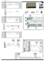
Descrizione
Modulo di espansione per ingressi, singolarmente programmabili, e collegamento
bus RS485 a 4 fi li. Completo di contenitore plastico.
Principali componenti scheda
1. Morsettiere per ingressi, collegabili nelle tipologie: normalm ente aperto NO
normalmente chiuso NC singolo bilanciamento SB doppio bilanciamento
DB contaimpulsi (o inerziale) CI e sensore in doppio bilanciamento DB
Esempio di collegamento di un sensore in DB e di un contatto magnetico
in SB.
2. Morsettiera del bus RS-485. Per collegare tastiere, moduli remoti e inseritori.
3. Jumper per tamper esterno. Se collegato, togliere il ponte.
4. Led rosso di segnalazione. Lampeggia quando il modulo comunica con la
centrale.
5. Dip-switch per impostazione indirizzo del modulo (vedi tabella).
6. Jumper per scollegare il morsetto + del bus da quello dei morsetti d’ingresso.
Dati tecnici
Tipo SMR8ICI
Alimentazione 12 V DC – 15 V DC
Assorbimento massimo 40 mA
Umidità relativa 25% - 75% senza condensa
IT 001SMR8ICI Modulo remoto di espansione per 8 ingressi
Indirizzo
modulo
Ingressi
CP 4020
Ingressi
CP 8048
Ingressi
CP 4060
Ingressi
CP 8096
Ingressi
CP 8192
Ingressi
CP 8200
0 Non valido
1 Non valido 9..16 Non valido 9..16 Non valido 9..16
2 17..24 13..20 17..24 17..24
3 25..32 25..32
4 33..40 33..40
5 41..48 41..48
6 49..56
7 57..64
8 65..72
9 73..80
10 81..88
11 89..96
12 97..104
13 105..112
14 113..120
15 121..128
Description
Expansion module for singularly programmable inputs, and the RS485 bus 4-wire
connection. Complete with plastic container.
Card main components
1. Input terminals, for the following connections: normally open NO normally
closed NC single balancing SB double balancing SB impulse
(or inertial) counter CI and double balancing sensor DB Example
connection of a DB sensor and of a magnetic contact in SB.
2. RS-485 bus terminal. To connect keypads, remote modules and inserters.
3. Jumper for outdoor tamper. Remove bridge if connected.
4. Red LED signal light. Flashes when the module communicates with the control
unit.
5. Dip-switch for setting the module address (see table).
6. Jumper for disconnecting the bus's + terminal from the that of the input
terminals.
Technical data
Type SMR8ICI
Power supply 12 V DC – 15 V DC
Max power draw 40 mA
Relative humidity 25% - 75% without condensation
EN 001SMR8ICI Remote expansion-module for 8 inputs
Address
module
Inputs
CP 4020
Inputs
CP 8048
Inputs
CP 4060
Inputs
CP 8096
Inputs
CP 8192
Inputs
CP 8200
0 Not valid
1 Not valid 9..16 Not valid 9..16 Not valid 9..16
2 17..24 13..20 17..24 17..24
3 25..32 25..32
4 33..40 33..40
5 41..48 41..48
6 49..56
7 57..64
8 65..72
9 73..80
10 81..88
11 89..96
12 97..104
13 105..112
14 113..120
15 121..128

Manual code 119RV80 - version 2 - 03/2013
© CAME cancelli automatici s.p.a. - The data and information reported in this installation manual are susceptible to change at any time and without obligation to notify users.
Description
Module d'expansion pour entrées, programmables individuellement, et connexion
bus RS485 à 4 fi ls. Doté d'un boîtier en plastique.
Principaux composants carte
1. Barrettes de connexion pour entrées, connectables selon les typologies suivantes
: normalement ouvert NO normalement fermé NC simple équilibrage SÉ
double équilibrage DÉ compteur d'impulsions (ou à inertie) CI et
capteur en double équilibrage DÉ Exemple de connexion d'un capteur en
DÉ et d'un contact magnétique en SÉ.
2. Barrette de connexion du bus RS-485. Pour connecter claviers, modules à
distance et actionneurs.
3. Cavalier pour autoprotection (tamper) externe. S'il est connecté, enlever le shunt.
4. Voyant rouge. Clignote lorsque le module communique avec la centrale.
5. Commutateur DIP pour confi guration de l'adresse du module (voir tableau).
6. Cavalier pour déconnecter la borne + du bus de la borne + des entrées.
Données techniques
Type SMR8ICI
Alimentation 12 V CC – 15 V CC
Absorption maximum 40 mA
Humidité relative 25% - 75% sans condensation
FR 001SMR8ICI Module d'expansion à distance pour 8 entrées
Adresse
module
Entrées
CP 4020
Entrées
CP 8048
Entrées
CP 4060
Entrées
CP 8096
Entrées
CP 8192
Entrées
CP 8200
0 Non valide
1 Non valide 9..16 Non valide 9..16 Non valide 9..16
2 17..24 13..20 17..24 17..24
3 25..32 25..32
4 33..40 33..40
5 41..48 41..48
6 49..56
7 57..64
8 65..72
9 73..80
10 81..88
11 89..96
12 97..104
13 105..112
14 113..120
15 121..128
Descripción
Módulo de expansión para entradas, programables individualmente y conexión bus
RS485 de 4 hilos. Con caja plástica.
Principales componentes tarjeta
1. Caja de bornes para entradas conectables en las tipologías: generalmente
abierto NO generalmente cerrado NC equilibrado simple SB
equilibrado doble DB cuentaimpulsos (o inercial) CI y sensor en doble
equilibrado DB Ejemplo de conexión de un sensor en DB y de un contacto
magnético en SB.
2. Caja de bornes del bus RS-485. Para conectar teclados, módulos e
interruptores.
3. Jumper para tamper externo. Si está conectado quitar el puente.
4. Led rojo de señalización. Parpadea cuando el módulo comunica con la central.
5. Dip-switch para programción dirección del módulo (véase tabla).
6. Jumper para desconectar el borne + del bus de aquel de los bornes de entrada.
Datos técnicos
Tipo SMR8ICI
Alimentación 12 V DC – 15 V DC
Absorción máxima 40 mA
Humedad relativa 25% - 75% sin condensación
ES 001SMR8ICI Módulo remoto de expansión para 8 entradas
Dirección
módulo
Entradas
CP 4020
Entradas
CP 8048
Entradas
CP 4060
Entradas
CP 8096
Entradas
CP 8192
Entradas
CP 8200
0 No correcto
1No
correcto 9..16 No
correcto 9..16 No
correcto 9..16
2 17..24 13..20 17..24 17..24
3 25..32 25..32
4 33..40 33..40
5 41..48 41..48
6 49..56
7 57..64
8 65..72
9 73..80
10 81..88
11 89..96
12 97..104
13 105..112
14 113..120
15 121..128

Manual code 119RV80 - version 2 - 03/2013
© CAME cancelli automatici s.p.a. - The data and information reported in this installation manual are susceptible to change at any time and without obligation to notify users.
Descrição
Módulo de expansão para entradas, programáveis individualmente, com ligação bus
RS485 a 4 fi os Em conjunto com caixa em plástico.
Componentes principais placa
1. Terminais para entradas, que se ligam nas seguintes formas: normalmente
aberto NO normalmente fechado NC balanceamento único SB
balanceamento duplo DB conta-impulsos (ou inercial) CI e sensor em
balanceamento duplo DB Exemplo de ligação de um sensor em DB e de
um contacto magnético em SB.
2. Terminal do bus RS-485. Para ligar teclados, módulos remotos e
transponders.
3. Jumper para tamper externo. Se ligado, retire a ponte.
4. Led vermelho de sinalização. Lampeja quando o módulo comunica com a
central.
5. Dip-switch para confi gurar o endereço do módulo (vide tabela).
6. Jumper para desligar o terminal + do bus daquele dos terminais de entrada.
Dados técnicos
Tipo SIR215WL
Alimentação 12 V DC – 15 V DC
Absorção máxima 40 mA
Humidade relativa 25% - 75% sem condensação
PT 001SMR8ICI Módulo remoto de expansão para 8 entradas.
Morada
módulo
Entradas
CP 4020
Entradas
CP 8048
Entradas
CP 4060
Entradas
CP 8096
Entradas
CP 8192
Entradas
CP 8200
0 Não válido
1 Não válido 9..16 Não válido 9..16 Não válido 9..16
2 17..24 13..20 17..24 17..24
3 25..32 25..32
4 33..40 33..40
5 41..48 41..48
6 49..56
7 57..64
8 65..72
9 73..80
10 81..88
11 89..96
12 97..104
13 105..112
14 113..120
15 121..128
Описание
Модуль расширения для отдельно программируемых входов и четырехжиль-
ная шина RS485. Модуль укомплектован пластмассовым корпусом.
Основные компоненты плата
1. Клеммные колодки для входов cо следующими вариантами подключения:
нормально-открытые (Н.О.) нормально-закрытые (Н.З.) простое
симметрирование SB двойное симметрирование DB счетчик им-
пульсов (или инерционный) CI и сенсор с двойным симметрированием
DB Пример подключения сенсора с двойным симметрированием и
магнитного контакта с простым симметрированием SB.
2. Клеммная колодка шины RS-485. Колодка предназначена для подключе-
ния кнопочных панелей, удаленных модулей и выключателей.
3. Перемычка для внешней кнопки тампера. Если кнопка тампера подключе-
на, уберите перемычку.
4. Красный светодиодный индикатор. Индикатор мигает во время обмена
данными между модулем и системой охранной сигнализации.
5. DIP-переключатели для настройки адреса модуля (см. таблицу).
6. Перемычка для отсоединения контакта "+" шины от входных контактов.
Технические характеристики
Тип SIR215WL
Электропитание =12—15 В
Макс. потребляемый ток 40 мA
Относительная влаж-
ность 25% — 75%, без образования конденсата
RU 001SMR8ICI Удаленный модуль расширения для 8 входов
Адрес
модуля
Входы
CP 4020
Входы
CP 8048
Входы
CP 4060
Входы
CP 8096
Входы
CP 8192
Входы
CP 8200
0 Недействителен
1
Недей-
ствите-
лен
9..16
Недей-
ствите-
лен
9..16
Недей-
ствите-
лен
9..16
2 17..24 13..20 17..24 17..24
3 25..32 25..32
4 33..40 33..40
5 41..48 41..48
6 49..56
7 57..64
8 65..72
9 73..80
10 81..88
11 89..96
12 97..104
13 105..112
14 113..120
15 121..128
-
 1
1
-
 2
2
-
 3
3
-
 4
4


