
Technical manual
Xenon beacon XB15

ii XENON BEACON XB15 TM332 Issue A October 2018 www.eaton.com
DISCLAIMER OF WARRANTIES AND LIMITATION OF LIABILITY
The information, recommendations, descriptions and safety notations in this document are based on Eaton Corporation’s
(“Eaton”) experience and judgment and may not cover all contingencies. If further information is required, an Eaton sales
office should be consulted. Sale of the product shown in this literature is subject to the terms and conditions outlined in
appropriate Eaton selling policies or other contractual agreement between Eaton and the purchaser.
THERE ARE NO UNDERSTANDINGS, AGREEMENTS, WARRANTIES, EXPRESSED OR IMPLIED, INCLUDING
WARRANTIES OF FITNESS FOR A PARTICULAR PURPOSE OR MERCHANTABILITY, OTHER THAN THOSE
SPECIFICALLY SET OUT IN ANY EXISTING CONTRACT BETWEEN THE PARTIES. ANY SUCH CONTRACT STATES THE
ENTIRE OBLIGATION OF EATON. THE CONTENTS OF THIS DOCUMENT SHALL NOT BECOME PART OF OR MODIFY
ANY CONTRACT BETWEEN THE PARTIES.
In no event will Eaton be responsible to the purchaser or user in contract, in tort (including negligence), strict liability or
other-wise for any special, indirect, incidental or consequential damage or loss whatsoever, including but not limited to
damage or loss of use of equipment, plant or power system, cost of capital, loss of power, additional expenses in the
use of existing power facilities, or claims against the purchaser or user by its customers resulting from the use of the
information, recommendations and descriptions contained herein. The information contained in this manual is subject to
change without notice.

iii
Xenon beacon XB15
English
XENON BEACON XB15 TM332 Issue A October 2018 www.eaton.com
Contents
1.0 INTRODUCTION ........................1
2.0 GENERAL SAFETY MESSAGES AND WARNINGS ...................1
3.0 INSTALLATION ................................................1
General ..........................................................1
Access to terminals .................................................2
4.0 OPERATION .........................................................................3
Wall mounted version only .................................................................... 3
All versions ................................................................................ 3
5.0 MAINTENANCE ......................................................................3
Removing/replacing xenon tube ................................................................ 4
6.0 SPECIAL CONDITIONS FOR SAFE USE ...................................................4
7.0 CERTIFICATION/APPROVALS ...........................................................4
IECEx units ................................................................................ 4
ATEX units ................................................................................. 4
EN54-23:2010 visual alarm device – beacon XB15 (24Vdc units only) ................................... 4
These units also have the following approvals: ..................................................... 5
EN54-23 coverage data & explanation of terminology ............................................... 5
Ceiling mounted devices- C-x-y ................................................................. 5
Wall mounted devices- W-x-y .................................................................. 5
8.0 FUNCTIONAL SAFETY ................................................................5
Introduction ................................................................................ 5
Assessment of functional safety – XB15 DC ...................................................... 6
Assessment of functional safety – XB15 AC ....................................................... 6
Conditions of safe use: ....................................................................... 8

iv XENON BEACON XB15 TM332 Issue A October 2018 www.eaton.com

1
Xenon beacon XB15
English
XENON BEACON XB15 TM332 Issue A October 2018 www.eaton.com
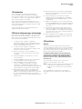
1.0 Introduction
These certified beacons have been designed for
use in potentially explosive atmospheres and harsh
environmental conditions. The enclosures are suitable for
use offshore or onshore, where light weight combined
with corrosion resistance is required.
The housing is manufactured completely from a U.V.
stable, glass reinforced polyester. Stainless steel screws
and mounting bracket are incorporated ensuring a totally
corrosion free product.
Units can be painted to customer specification and
supplied with identification labels.
2.0 General safety messages and warnings
All instructions and safety messages in this manual must
be followed to allow safe installation of the device. The
device must only be installed and maintained by correctly
trained site personnel/installers.
I. To reduce the risk of ignition of hazardous
atmospheres and shock, do not apply power to the
device until installation has been completed and the
device is fully sealed and secured.
II. To reduce the risk of ignition of hazardous
atmospheres and shock, keep device tightly closed
when the circuit is energised.
III. Before removing the cover for installation or
maintenance, ensure that the power to the device
is isolated.
IV. Following installation, test the device to ensure
correct operation.
V. Following installation ensure a copy of this manual
is made available to all operating personnel.
VI. When installing the device, requirements for
selection, installation and operation should be
referred to e.g. IEE Wiring Regulations and the
‘National Electrical Code’ in North America. Additional
national and/or local requirements may also apply.
VII. Cable termination should be in accordance with
specification applying to the required application.
MEDC recommends that all cables and cores should
be correctly identified. Please refer to the wiring
diagram in this manual (or separate diagram provided
with the unit).
VIII. Ensure that only the correct listed or certified cable
glands are used and that the assembly is shrouded
and correctly earthed.
IX. Ensure that only the correct listed or certified
stopping plugs are used to blank off unused gland
entry points and that the NEMA/IP rating of the unit
is maintained.
X. MEDC recommend the use of a sealing compound
such as HYLOMAR PL32 on the threads of all glands
and stopping plugs in order to maintain the IP rating
of the unit.
XI. The internal earth terminal, where fitted, must be
used for the equipment grounding and the external
terminal, if available, is for a supplementary bonding
connection where local codes or authorities permit or
require such a connection.
XII. When installing the device, MEDC recommends the
use of stainless steel fasteners. Ensure that all nuts,
bolts and fixings are secure.
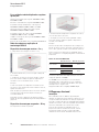
3.0 Installation
General
The device can either be directly mounted using the
inserts moulded into the back of the enclosure (standard),
or an optional backstrap can be fixed to the base of the
device thus giving an optional mounting position for when
direct mounting is deemed unsuitable.
For EN54-23:2010 Compliance the mounting back
strap must be positioned in the horizontal plane. If
the direct mount option is ordered the mounting
holes must also be on the same horizontal plane as
the back strap.
The 2 off inserts in the base of the enclosure are
designed to accept an M5 screw or bolt.
ote:N For direct mounting, observe the following formula
to determine the required fixing screw length:
Length of screw = Thickness of mounting surface
+ 10mm.
The 2 off Ø8.5mm mounting holes in the optional
backstrap have been designed to accept an M8 screw
or bolt.

2 XENON BEACON XB15 TM332 Issue A October 2018 www.eaton.com
Xenon beacon XB15
English
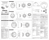
Access to terminals
Unscrew the grub screw (2.0mm A/F hexagon key) in the
flange of the cover 3 full turns (Do not fully unscrew).
Unscrew and remove the cover and lens assembly using
the spanner supplied to gain access to the inside of the
unit. Unscrew the 2 off thumbscrews and carefully lift
the PCB assembly clear of the mounting pillars to gain
access to the terminals.
Once termination is complete, replace the PCB
assembly onto the mounting pillars and fully tighten
the thumbscrews, taking care not to overtighten them.
Replace the cover assembly, ensuring the cover is fully
screwed down. There should be a maximum gap of
0.2mm between the faces of the cover and enclosure
to ensure o-ring compression. Ensure the cover seal is
correctly seated in its groove during re-assembly.
Re-tighten the grub screw (2.0mm A/F hexagon key) in
the cover flange to secure the cover.
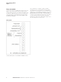
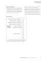
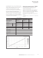
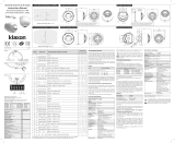
Wiring detail
* Relay initiate option is not available for EN54-23 version

3XENON BEACON XB15 TM332 Issue A October 2018 www.eaton.com
Xenon beacon XB15
English
4.0 Operation
The beacon can be powered directly or initiated by a
24Vdc relay or telephone ringing signal if requested when
ordered
The operating voltage, tube energy and flash rate of the
unit is stated on the unit label.The flash rate is pre- set by
MEDC prior to shipping and cannot be adjusted once set.
For EN54-23:2010 Compliance only the 24Vdc, 60 fpm
version is approved (with clear or red lens)
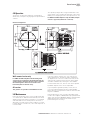
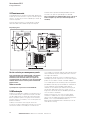
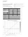
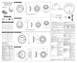
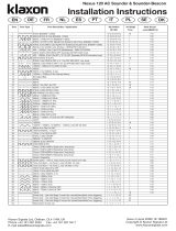
General arrangement
Wall mounted version only
For EN54-23:2010 Compliance the mounting back
strap must be positioned in the horizontal plane (as
shown above). If the direct mount option is ordered
the mounting holes must also be on the same
horizontal plane as the back strap.
All versions
The guard is not possible on the EN54-23 version.
5.0 Maintenance
During the working life of the unit, it should require little
or no maintenance. GRP will resist attack by most acids,
alkalis and chemicals and is as resistant to concentrated
acids and alkalis as most metal products. However, if
abnormal or unusual environmental conditions occur due
to plant damage or accident etc., then visual inspection is
recommended.
If the unit requires cleaning, then only clean exterior
with a damp cloth to avoid electro-static charge build
up. Replacement of the xenon tube (see below) can be
carried out by competent site personnel. Other repairs
should be undertaken by returning the unit to MEDC.
If a unit fault should occur, then the unit can be repaired
by MEDC. All parts of the unit are replaceable.
If you acquired a significant quantity of units, then it
is recommended that spares are also made available.
Please discuss your requirements with the Technical Sales
Engineers at MEDC.
During maintenance, if the cover/lens assembly grease
needs to be re-applied, a PFPE (Perfluoropolyether) based
grease such as Krytox GPL203 by DuPont or Perfluorolube
22/6 by Performance Fluids Ltd. Should be used, to
prevent damage to the O-ring.

4 XENON BEACON XB15 TM332 Issue A October 2018 www.eaton.com
Xenon beacon XB15
English
Removing/replacing xenon tube
Unscrew the grub screw (2.0mm A/F hexagon key) in the
flange of the cover 3 full turns (Do not fully unscrew).
Unscrew and remove the cover and lens assembly using
the spanner supplied to gain access to the inside of
theunit.
Remove the old tube by unscrewing the terminal block
fixings. The replacement tube can now be fitted (see
xenon tube installation sheet, which is supplied with the
replacement tubes).
Once the new tube has been correctly fitted, replace the
cover assembly, ensuring the cover is fully screwed down.
There should be a maximum gap of 0.2mm between
the faces of the cover and enclosure to ensure o-ring
compression. Ensure the cover seal is correctly seated in
its groove during re-assembly. Re-tighten the grub screw
(2.0mm A/F hexagon key) in the cover flange to secure
the cover.
6.0 Special conditions for safe use
1. Painting and other surface finishes, other than those
applied by the manufacturer, are not permitted.
2. In order to maintain the dust tight integrity of the
enclosures (IP6X), the threads of cable entry devices
and stopping plugs shall be sealed in accordance
with the applicable code of practice for flameproof
installation.
7.0 Certication/approvals
IECEx units
Certified to IEC60079-0, IEC60079-1 & IEC60079-31
Ex d unit (IEC certification No. IECEx BAS 05.0048X)
Ex db IIC T
G
Gb
Ex tb IIIC T
D
Db IP66/67
T
amb.
Tube Energy T-rating (T
G
) T-rating (T
D
) T
amb.
15J
T4 T135°C (-55°C to +70°C)
T5 T100°C (-55°C to +40°C)
10J
T4 T135°C (-55°C to +70°C)
T5 T100°C (-55°C to +55°C)
T6 T85°C (-55°C to +40°C)
5J
T5 T100°C (-55°C to +70°C)
T6 T85°C (-55°C to +55°C)
The IECEx certificate and product label carry the IECEx
equipment protection level marking
Gb
Db
Where Gb signifies suitability for use in a Zone 1 surface
industries area in the presence of gas.
Where Db signifies suitability for use in a Zone 21 surface
industries area in the presence of dust.
ATEX units
Certified to EN60079-0, EN60079-1 & EN60079-31
Ex d unit (ATEX certification No. Baseefa04ATEX0009X)
Ex db IIC T
G
Gb
Ex tb IIIC T
D
Db IP66/67
T
amb.
Tube Energy T-rating (T
G
) T-rating (T
D
) T
amb.
15J
T4 T135°C (-55°C to +70°C)
T5 T100°C (-55°C to +40°C)
10J
T4 T135°C (-55°C to +70°C)
T5 T100°C (-55°C to +55°C)
T6 T85°C (-55°C to +40°C)
5J
T5 T100°C (-55°C to +70°C)
T6 T85°C (-55°C to +55°C)
The ATEX certificate and product label carry the ATEX
group and category marking:
II 2 GD
Where:
Signifies compliance with ATEX
II Signifies suitability for use in surface industries
2 Signifies suitability for use in a zone 1 area
G Signifies suitability for use in the presence of gases
D Signifies suitability for use in the presence of dust
EN54-23:2010 visual alarm device – beacon
XB15 (24Vdc units only)
Rating 21.6v- 26.4v DC Absolute. Amps 0.99
Environment Type B Outdoor applications
IP code (IP33C) to BS EN 60529:1992
The Red lens Beacon is supplied with the following
LPCBmarkings.
The White lens Beacon is supplied with the following
LPCB markings.
This signifies unit compliance to the relevant European
directives, in this case 89/106/EEC, along with the name
and number of the notified body issuing the certificate
ofconformity.

5XENON BEACON XB15 TM332 Issue A October 2018 www.eaton.com
Xenon beacon XB15
English
These units also have the following approvals:
Main Harmonics (AC) to EN61000-6-3:2007 /
IEC61000-3-2:2006
Conducted Emissions (DC) to EN61000-6-3:2007
Radiated Field Immunity (DC and AC) to EN61000-6-
2:2005 / IEC61000-4-3:2002 + A1:2002
Electrical Fast Transients/Bursts (DC and AC) to EN61000-
6-2:2005/ IEC61000-4-4:2004
Surge Immunity (DC and AC) to EN61000-6-2:2005 /
IEC61000-4-5:1995 + A1:2000
Dips and Interruptions (AC) to EN61000-6-2:2005 /
IEC61000-4-11:2004
Ingress protection (IP66 & 67) to BS EN 60529:92
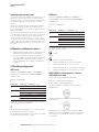
EN54-23 coverage data & explanation of
terminology
Ceiling mounted devices- C-x-y
C - Ceiling mounted Device.
x - The maximum height of 3, 6 or 9m at which the VAD
may be mounted.
y - The diameter in metres of the cylindrical volume
covered (to a minimum level of 0.4 lux) when the device
is mounted to the ceiling at a height of 3, 6, or 9 m.
Example:
C-3-32 corresponds to a ceiling mounted device giving a
coverage cylindrical volume of 32 m, when mounted at
3m.
Note: The projected space sits within the cylindrical
volume and ensures that all areas meet the required
illumination of 0.4 lux.
Tip: To convert the coverage diameter y to the width of a
square room.
Width of square room = y/1.414 m.
Wall mounted devices- W-x-y
W - Wall mounted Device.
x - The maximum height of the device on the wall in
metres, with a minimum value of 2.4.m.
y – The width in metres of the square volume covered (to
a minimum level of 0.4 lux) when the device is mounted
at a height x.
Example:
W-8-13 corresponds to a wall mounted device giving a
coverage cuboid volume of 8 m x 13 m x 13 m, when
mounted at a height of 8 m.
Tip: if the area to be covered is not square, use the larger
of either the length or width to ensure that the whole
area is covered.
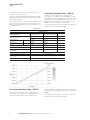
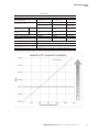
MEDC VAD Coverage data
Ceiling mounted Wall mounted
C-3-16
W-3-5Red lens C-6-6
White lens
C-3-32
W-8-13
C-6-31
C-9-12
Further information is available via the Code of practice
(CoP 0001.)
CoP 0001 provides detailed guidance and
recommendations on the planning, design, installation,
commissioning and maintenance of VAD’s. A copy is
available at the following website:
http://www.redbooklive.com/pdf/CoP-0001-1-0.pdf
8.0 Functional safety
Introduction
The XB15 Beacon has been designed for use in potentially
explosive atmospheres and harsh environmental
conditions. The glass reinforced polyester enclosures are
suitable for use offshore or onshore, where light weight
combined with corrosion resistance is required.
The safety function of the Beacon is to provide an
intermittent spherical visual warning light when the
correct voltage is applied to the unit. The DC versions of
the Beacon are designed to operate on a supply voltage
tolerance of +/- 20%; the AC versions of the beacon are
designed to operate on a supply voltage tolerance of
+/- 10%.

6
Xenon beacon XB15
English
The telephone initiate versions of the Beacon are not
included in this safety manual.
Under No fault (Normal) Operating conditions the XB15
Beacon will provide a spherical visual warning light when
required by the system.
Under fault conditions the failure mode of the Beacon is a
failure to provide a spherical visual warning light. For the
failure rate associated with this failure mode please refer
to the table below.
Assessment of functional safety – XB15 DC
This Beacon is intended for use in a safety system
conforming to the requirements of IEC61508. Sira Test
& certification Ltd has conducted a Failure Modes Effect
and Diagnostic Analysis (FMEDA) of the DC version of
XB15 Xenon Beacon against the requirements of IEC
61508-2 using a Proof Test Interval of 730hrs.
The results are shown below and are based on Route 1H.
The Beacon is classed as a Type B device.
Safety function:
‘To provide a spherical cycled visual warning light when energized’.
XB15 DC Beacon
Summary of Clauses
2/7.4.2 and 2/7.4.4
XB15 Xenon Beacon
Single Mode (1oo1)
XB15 Xenon Beacon
Redundant Mode (1oo2)
Verdict
Architectural constraints
Safe Failure Fraction (SFF)
HFT=0 HFT=1 Type B
62% 62% SIL 1
Random hardware
failures: [h
-1
]
λ
DD
λ
DU
0.00E+00
5.85E-06
0.00E+00
5.85E-07
Random hardware
failures: [h
-1
]
λ
SD
λ
SU
0.00E+00
9.53E-06
0.00E+00
9.53E-07
Diagnostic coverage (DC) 0.00% 0.00%
PFD @ PTI = 730Hrs, MTTR = 8 Hrs 2.18E-03 2.18E-04 SIL 2 (1oo1)
Average freq. of dangerous failure (high
demand-PFH)[h
-1
]
5.85E-06 5.85E-07 SIL 1 (1oo1)
Hardware safety integrity compliance
[
Route 1
H
Systematic safety integrity compliance See report R56A24816B
Systematic Capability
(SC1, SC2, SC3, SC4)
SC2 (R56A24816B)
Hardware safety integrity achieved Limited to: SIL 1 (1oo1) & SIL 2 (1oo2) due to SFF value.
Assessment of functional safety – XB15 AC
This Beacon is intended for use in a safety system
conforming to the requirements of IEC61508. UL has
conducted a Failure Modes Effect and Diagnostic
Analysis (FMEDA) of the XB15 Xenon Beacon against the
requirements of IEC 61508-2 using a Proof Test Interval of
8760hrs.
The results are shown below and are based on Route 1
H
.
The Beacon is classed as a Type B device.
XENON BEACON XB15 TM332 Issue A October 2018 www.eaton.com

7
Xenon beacon XB15
English
Safety function:
‘To provide a spherical cycled visual warning light when energized’.
XB15 AC Beacon
Summary of Clauses
2/7.4.2 and 2/7.4.4
XB15 Xenon Beacon
Single Mode (1oo1)
XB15 Xenon Beacon
Redundant Mode (1oo2)
Verdict
Architectural constraints
Safe Failure Fraction (SFF)
HFT=0 HFT=1 Type B
72% 72% SIL 1 (1oo1)
SIL 2 (1oo2)
Random hardware
failures: [h
-1
]
λ
DD
λ
DU
6.45E-09
3.48E-07
6.45E-10
3.48E-08
Random hardware
failures: [h
-1
]
λ
SD
λ
SU
0.00E+00
8.84E-07
0.00E+00
8.84E-08
Diagnostic coverage (DC) 0.00% 0.00%
PFD @ PTI = 8760Hrs, MTTR = 8 Hrs 1.53E-03 1.53E-04 SIL 2 (1oo1)
Average freq. of dangerous failure (high
demand-PFH)[h
-1
]
3.48E-07 3.48E-08 SIL 3 (1oo1)
Hardware safety integrity compliance Route 1
H
Systematic safety integrity compliance Route 1
S
Systematic Capability
(SC1, SC2, SC3, SC4)
SC2
Hardware safety integrity achieved Limited to: SIL 1 (1oo1) & SIL 2 (1oo2) due to SFF value.
XENON BEACON XB15 TM332 Issue A October 2018 www.eaton.com

8
Xenon beacon XB15
English
Conditions of safe use:
The following conditions apply to the installation,
operation and maintenance of the XB15. Failure to
observe these may compromise the safety integrity of the
Beacon.
1. The user shall comply with the requirements given in
this Safety manual in regard to all relevant functional
safety aspects such as application of use, installation,
operation, maintenance, proof tests, maximum
ratings, environmental conditions, repair, etc.
2. If the Beacon is to be used on a Fire Alarm system it
is recommended as per BS 5839 part 1 (eq. EN 54),
that the product is tested at least once a week. In all
other applications it is strongly recommended to test
the product at least once a year.
3. Selection of this equipment for use in safety
functions and the installation, configuration, overall
validation, maintenance and repair shall only be
carried out by competent personnel, observing all the
manufacturer’s conditions and recommendations in
the user documentation.
4. All information associated with any field failures
of this product should be collected under a
dependability management process (e.g., IEC
60300-3-2) and reported to the manufacturer.
5. If the product is used in a redundant installation,
both hardware safety integrity and systematic safety
integrity for SIL 2 can be achieved. The installation
must be such as to ensure sufficient protection
against common cause failures and independence
from cascading failures.
XENON BEACON XB15 TM332 Issue A October 2018 www.eaton.com

9
Xenon beacon XB15
Português Brasileiro
Contents
1.0 INTRODUÇÃO .
.................................................................... 10
2.0 PRECAUÇÕES E ADVERTÊNCIAS GERAIS DE SEGURANÇA ................................10
3.0 INSTALAÇÃO .......................................................................10
Generalidades ................................................................................. 10
Acesso aos terminais ............................................................................. 11
4.0 FUNCIONAMENTO ..................................................................12
Versão exclusiva para montagem em parede ......................................................... 12
Todas as versões ................................................................................. 12
5.0 MANUTENÇÃO .....................................................................12
Remoção/substituição do tubo de xenônio ....................................................... 13
6.0 CONDIÇÕES ESPECIAIS PARA A UTILIZAÇÃO SEGURA ....................................13
7.0 CERTIFICAÇÃO/APROVAÇÕES .........................................................13
Unidades IECEx .................................................................................. 13
Unidades ATEX .................................................................................. 13
EN54-23:2010
dispositivo de alarme visual – sinalizador luminoso de xenônio XB15
(apenas para unidades de 24Vcc) ............................................................. 13
Essas unidades também dispõem das seguintes aprovações: .......................................14
Dados de cobertura e explicação de terminologia EN54-23 ......................................... 14
Dispositivos de montagem em tetos - C-x-y ...................................................... 14
Dispositivos de montagem em paredes - W-x-y .. ..................................................14
8.0 SEGURANÇA FUNCIONAL .
...........................................................14
Introdução ................................................................................ 14
Avaliação da segurança funcional – XB15 DC ..................................................... 15
Avaliação da segurança funcional – XB15 AC ..................................................... 16
Condições de uso seguro: .......................................................................... 17
XENON BEACON XB15 TM332 Issue A October 2018 www.eaton.com

10
Xenon beacon XB15
Português Brasileiro
1.0 Introdução
Estes sinalizadores luminosos giratórios certificados
foram projetados para uso em ambientes potencialmente
explosivos e condições ambientais adversas. As carcaças
são adequadas para utilização marítima ou terrestre, onde
são requeridas características de leveza combinadas com
resistência à corrosão.
A carcaça é totalmente fabricada em poliéster reforçado
com fibra de vidro e resistente à radiação ultravioleta. Para
assegurar um produto resistente à corrosão, os parafusos
e os suportes de montagem são de aço inoxidável.
As unidades podem ser pintadas segundo especificações
do cliente e são fornecidas com placas de identificação.
2.0 Precauções e advertências gerais de
segurança
Todas as instruções e mensagens de segurança
apresentadas neste manual devem ser respeitadas para
permitir a instalação segura do dispositivo. A instalação e
manutenção do dispositivo somente deverá ser realizada
por pessoal local/instaladores corretamente treinados.
I. Para reduzir o risco de ignição em ambientes
perigosos e de impacto, não aplique alimentação
elétrica ao dispositivo até que a instalação esteja
terminada e o dispositivo totalmente vedado e fixado.
II. Para reduzir o risco de ignição em caso de ambientes
perigosos ou de impactos, mantenha o dispositivo
hermeticamente fechado ao energizar o circuito.
III. Antes de remover a tampa para instalação ou
manutenção, certifique-se de que a alimentação
elétrica do dispositivo esteja isolada.
IV. Ao concluir a instalação, teste o dispositivo para se
certificar de que funciona corretamente.
V. Ao concluir a instalação, disponibilize uma cópia
deste manual a todo o pessoal encarregado do
funcionamento do dispositivo.
VI. Ao instalar o dispositivo, é necessário consultar os
requisitos para a seleção, instalação e funcionamento,
tais como, as normas de cabeamento do IEE
(Instituto Americano de Engenheiros Eletricistas) e
o ‘National Electrical Code’ (Código Elétrico Nacional
americano). Também podem ser aplicáveis outros
requisitos nacionais e/ou locais.
VII. A terminação dos cabos deve estar em conformidade
com as especificações referentes à aplicação em
questão. A MEDC recomenda que todos os cabos
e condutores sejam identificados corretamente.
Consulte o esquema elétrico reproduzido neste
manual (ou o esquema separado fornecido com
a unidade).
VIII. Certifique-se de que sejam utilizados exclusivamente
prensa-cabos corretos, enumerados ou certificados
e que o conjunto fique blindado e aterrado
corretamente.
IX. Certifique-se de que sejam utilizados exclusivamente
bujões de vedação corretos, enumerados ou
certificados, para vedar os pontos de entrada não
utilizados do prensa-cabos e que a classificação
NEMA/IP da unidade seja mantida.
X. A MEDC recomenda a aplicação de um produto
selante, como o HYLOMAR PL32, nas roscas de
todos os prensa-cabos e bujões de vedação, para
manter a classificação IP da unidade.
XI. O terminal de terra interno, quando presente, deve
ser utilizado para o aterramento do equipamento e
o terminal externo, se disponível, destina-se a uma
conexão suplementar, se for permitida ou exigida pela
legislação ou autoridades locais.
XII. Para a instalação do dispositivo, a MEDC recomenda
a utilização de elementos de fixação de aço inox.
Certifique-se de que todas as porcas, parafusos
e elementos de fixação estejam apertados
corretamente.
3.0 Instalação
Generalidades
O dispositivo pode ser montado diretamente, utilizando os
insertos moldados na parte traseira da caixa (padrão) ou é
possível fixar uma correia traseira na base do dispositivo
para, dessa forma, ter uma posição de montagem
opcional quando a montagem direta for considerada
inadequada.
Para conformidade com a EN54-23:2010, a montagem
da lâmina traseira deve ser posicionada no plano
horizontal. Se a opção de montagem direta for
solicitada, os furos de montagem também devem
estar na mesma posição horizontal da lâmina traseira.
Os 2 insertos presentes na base da caixa foram
concebidos para aceitar parafusos de rosca M5.
Nota: Para a montagem direta, deverá ser utilizada
a seguinte fórmula para determinar o compri-
mento dos parafusos de fixação necessários:
Comprimento do parafuso = 10 mm + Espessura
da superfície de montagem
Os 2 furos de montagem Ø 8,5 mm na lâmina traseira
opcional foram concebidos para aceitar parafusos de
rosca M8.
XENON BEACON XB15 TM332 Issue A October 2018 www.eaton.com

11
Xenon beacon XB15
Português Brasileiro
Acesso aos terminais
Desaparafuse os parafusos Allen (Chave hexagonal de
2,0 mm A/F) existentes no flange da tampa 3 voltas
completas. (Não desaparafuse completamente). Solte e
retire a tampa e o conjunto da lente utilizando a chave
fornecida para ter acesso ao interior da unidade. Solte
os 2 parafusos de aperto manual e cuidadosamente
levante o conjunto da PCI para fora de seus pilares de
montagem para ter acesso aos terminais.
Uma vez concluída a terminação, recoloque o conjunto
da PCI em seus pilares de montagem e aperte
firmemente os parafusos, tendo o cuidado de não
aplicar aperto excessivo. Substitua o conjunto da tampa,
assegurando-se de que esta tenha sido totalmente
rosqueada. Deve existir um espaço máximo de 0,2mm
entre as superfícies do gabinete e da tampa, para
garantir a compressão do O-ring. Assegure-se de que a
vedação da tampa tenha sido corretamente assentada
em sua ranhura durante a remontagem. Aperte
novamente os parafusos Allen (chave hexagonal A/F de
2,0 mm) no flange da tampa para prendê-la firmemente.
Detalhes da fiação
* Opção iniciar transmissão indisponível para a versão EN54-23.
XENON BEACON XB15 TM332 Issue A October 2018 www.eaton.com

12
Xenon beacon XB15
Português Brasileiro
4.0 Funcionamento
O sinalizador luminoso poderá ser alimentado diretamente,
iniciado por um relé de 24 Vcc ou por um sinal de toque de
telefone, se essas opções forem indicadas por ocasião da
emissão do pedido.
A tensão de funcionamento, energia do tubo e taxa de
flash da unidade está indicada na respectiva etiqueta.
A taxa de flash é pré-determinada pela MEDC antes da
remessa e não pode ser ajustada após ser definida.
Para conformidade com a EN54-23:2010, apenas a versão de
24 Vcc e 60 fpm é aprovada (com lente transparente ou
vermelha).
Disposição geral
Versão exclusiva para montagem em parede
Para conformidade com a EN54-23:2010, a montagem
da lâmina traseira deve ser posicionada no plano
horizontal (como mostrado acima). Se a opção de
montagem direta for solicitada, os furos de montagem
também devem estar no mesmo plano horizontal da
lâmina traseira
Todas as versões
A proteção não é possível na versão EN54-23.
5.0 Manutenção
Durante a sua vida útil, a unidade necessita de pouca ou
nenhuma manutenção. O poliéster reforçado com fibra
de vidro (GRP) resiste ao ataque da maioria dos ácidos,
bases e produtos químicos em geral, sendo resistente
a ácidos e bases concentrados, como a maior parte dos
produtos metálicos.
Todavia, recomenda-se uma inspeção visual caso
aconteçam condições ambientais anormais ou incomuns
decorrentes de danos na instalação ou acidentes etc.
Se a unidade necessitar de limpeza, limpe apenas a parte
externa utilizando um pano úmido para evitar o acúmulo
de cargas eletrostáticas.
A substituição do tubo de xenônio (ver abaixo) pode ser
realizada por pessoal competente no local. Outros reparos
podem ser executados enviando a unidade à MEDC.
Se a unidade apresentar uma falha, poderá ser reparada
pela MEDC. Todas as peças da unidade são substituíveis.
Se tiver adquirido uma quantidade significativa de
unidades, recomendamos que também tenha as peças
de reposição disponíveis. Entre em contato com os
Engenheiros de Vendas Técnicas da MEDC para discutir
com eles suas necessidades.
Durante a manutenção, caso seja necessário aplicar
novamente o lubrificante do conjunto da tampa/lente,
deve-se usar um lubrificante à base de perfluoropoliéster
(PFPE), como o Krytox GPL203 da DuPont ou
Perfluorolube 22/6 da Performance Fluids Ltd., a fim de
evitar danos ao O-ring.
XENON BEACON XB15 TM332 Issue A October 2018 www.eaton.com

13
Xenon beacon XB15
Português Brasileiro
Remoção/substituição do tubo de xenônio
Desaparafuse os parafusos Allen (Chave hexagonal de
2,0 mm A/F) existentes no flange da tampa 3 voltas
completas. (Não desaparafuse completamente.) Solte e
retire a tampa e o conjunto da lente utilizando a chave
fornecida para ter acesso ao interior da unidade.
Retire o tubo a ser substituído, soltando as fixações do
bloco de terminais. A substituição do tubo de xenônio
poderá agora ser instalada (consulte a ficha de instalação
do tubo fornecida com os tubos de substituição). Quando
o tubo novo estiver corretamente instalado, substitua
o conjunto da tampa, certificando-se de que a tampa
esteja totalmente parafusada. Deve existir um espaço
máximo de 0,2 mm entre as superfícies do gabinete e da
tampa, para garantir a compressão do O-ring. Assegure-se
de que a vedação da tampa tenha sido corretamente
assentada em sua ranhura durante a remontagem. Aperte
novamente os parafusos Allen (chave hexagonal A/F de
2,0 mm) no flange da tampa para prendê-la firmemente.
6.0 Condições especiais para a utilização
segura
1. Não são permitidos outras tintas e acabamentos de
superfície diferentes dos aplicados pelo fabricante.
2. Para manter a integridade da caixa em relação à
poeira (IP6X), as roscas dos dispositivos de entrada
de cabos e dos bujões de vedação devem ser seladas
em conformidade com as diretrizes aplicáveis a
instalações resistentes ao fogo.
7.0 Certicação/aprovações
Unidades IECEx
Certificadas segundo IEC60079-0, IEC60079-1 e IEC60079-31
Unidade Ex d (Nº de certificado IEC IECEx BAS 05.0048X)
Ex db IIC T
G
Gb
Ex tb IIIC T
D
Db IP66/67
T
amb.
Energia do tubo
Classificação
T (T
G
)
Classificação
T (T
D
) T
amb.
15 J
T4 T135 °C (-55°C a +70°C)
T5 T100 °C (-55°C a +40°C)
10 J
T4 T135 °C (-55°C a +70°C)
T5 T100 °C (-55°C a +55°C)
T6 T85 °C (-55°C a +40°C)
5 J
T5 T100 °C (-55°C a +70°C)
T6 T85 °C (-55°C a +55°C)
O certificado IECEx e a etiqueta do produto contêm a
marcação do nível de proteção IECEx de equipamento
Gb
Db
Onde Gb significa adequado para uso em áreas industriais
de superfície de Zona 1 na presença de gás.
Onde Db significa adequado para uso em áreas industriais
de superfície de Zona 21 na presença de poeira.
Unidades ATEX
Certificadas segundo EN60079-0, EN60079-1 e
EN60079-31
Unidade Ex d (certificado ATEX Nº Baseefa04ATEX0009X)
Ex db IIC T
G
Gb
Ex tb IIIC T
D
Db IP66/67
T
amb.
Energia do tubo
Classificação
T (T
G
)
Classificação
T (T
D
) T
amb.
15 J
T4 T135 °C (-55°C a +70°C)
T5 T100 °C (-55°C a +40°C)
10 J
T4 T135 °C (-55°C a +70°C)
T5 T100 °C (-55°C a +55°C)
T6 T85 °C (-55°C a +40°C)
5 J
T5 T100 °C (-55°C a +70°C)
T6 T85 °C (-55°C a +55°C)
O certificado ATEX e a etiqueta do produto contêm a
marcação de grupo e categoria ATEX:
II 2 GD
Onde:
Significa conformidade com as normas ATEX
II Significa adequado para uso em indústrias de
superfície
2 Significa adequado para uso em uma área de zona 1
G Significa adequado para uso na presença de gases
D Significa adequado para uso na presença de poeira
EN54-23:2010 dispositivo de alarme visual –
sinalizador luminoso de xenônio XB15 (apenas
para unidades de 24Vcc)
Classificação 21,6v- 26,4v DC Absoluta. Amps. 0,99
Aplicações externas em ambientes do Tipo B Código IP
(IP33C) segundo BS EN 60529:1992
As lentes Vermelhas do Sinalizador Luminoso são
fornecidas com as seguintes marcações LPCB.
As lentes Brancas do Sinalizador Luminoso são fornecidas
com as seguintes marcações LPCB.
Isso significa que a unidade está em conformidade
com as diretivas europeias pertinentes, neste caso a
Diretiva 89/106/EEC, juntamente com o nome e número
do organismo notificado que emitiu o certificado de
conformidade.
XENON BEACON XB15 TM332 Issue A October 2018 www.eaton.com

14
Xenon beacon XB15
Português Brasileiro
Essas unidades também dispõem das seguintes
aprovações:
Harmônicos principais (AC) segundo EN61000-6-3:2007/
IEC61000-3-2:2006
Emissões conduzidas (DC) segundo EN61000-6-3:2007
Imunidade a Campo Irradiado (DC e AC) segundo
EN61000-6-2:2005/IEC61000-4-3:2002 + A1:2002
Transientes elétricos rápidos (DC e AC) segundo
EN61000-6-2:2005/IEC61000-4-4:2004
Imunidade a surtos (DC e AC) segundo EN61000-6-
2:2005/IEC61000-4-5:1995 + A1:2000
Subidas e interrupções (AC) segundo EN61000-6-2:2005/
IEC61000-4-11:2004
Proteção da entrada (IP66 e 67) segundo BS EN 60529:92
Dados de cobertura e explicação de
terminologia EN54-23
Dispositivos de montagem em tetos - C-x-y
C - Dispositivos de montagem em tetos - C-x-y.
x - A altura máxima de 3, 6 ou 9 m na qual o VAD pode
ser montado.
y - O diâmetro em metros do volume cilíndrico coberto
(a um nível mínimo de 0,4 lux) quando o dispositivo é
montado no teto a uma altura de 3, 6, ou 9 m.
Exemplo:
C-3-32 corresponde a um dispositivo montado em teto
que fornece uma cobertura de volume cilíndrico de 32 m,
quando montado a 3 m.
Nota: O espaço projetado fica dentro do volume cilíndrico
e assegura que todas as áreas atinjam a iluminação
necessária de 0,4 lux.
Dica: Para converter o diâmetro da cobertura y para a
largura de uma sala quadrada. Largura da sala quadrada =
y/1,414 m.
Dispositivos de montagem em paredes - W-x-y
W - Dispositivo montado em paredes.
x - A altura máxima do dispositivo na parede em metros,
com um valor mínimo de 2,4 m.
y - A largura em metros do volume quadrado coberto
(a um nível mínimo de 0,4 lux) quando o dispositivo é
montado, a uma altura x.
Exemplo:
W- 8-13 corresponde a um dispositivo de montagem em
parede que dá um volume cuboide de cobertura de 8 m x
13 m x 13 m, quando montado a uma altura de 8 metros.
Dica: se a área a ser coberta não for quadrada, utilize o
maior comprimento ou largura para garantir a cobertura de
toda a área.
Dados de cobertura MEDC VAD
Montado em tetos Montado em paredes
Lentes vermelhas
C-3-16
W-3-5C-6-6
Lentes brancas
C-3-32
W-8-13
C-6-31
C-9-12
Informações adicionais estão disponíveis por meio dos
códigos de práticas (CoP 0001).
O CoP 0001 fornece orientações e recomendações
detalhadas sobre o planejamento, projeto, instalação,
comissionamento e manutenção de VADs. Uma cópia
está disponível no seguinte site:
http://www.redbooklive.com/pdf/CoP-0001-1-0.pdf
8.0 Segurança funcional
Introdução
Este sinalizador luminoso XB15 foi projetado para
utilização em ambientes potencialmente explosivos e em
condições ambientais adversas. As carcaças de poliéster
reforçado com fibra de vidro são adequadas para utilização
marítima ou terrestre, onde são requeridas características
de leveza combinadas com resistência à corrosão.
A função de segurança do sinalizador luminoso é
proporcionar uma luz de advertência visual esférica
intermitente quando a tensão correta é aplicada à
unidade. As versões DC do sinalizador luminoso são
XENON BEACON XB15 TM332 Issue A October 2018 www.eaton.com

15
Xenon beacon XB15
Português Brasileiro
projetadas para funcionar com uma tolerância de tensão
de alimentação de +/- 20%; as versões AC do sinalizador
luminoso são projetadas para funcionar com uma
tolerância de tensão de alimentação de +/- 10%.
As versões de iniciação por telefone do sinalizador
luminoso não estão incluídas neste manual de segurança.
Em condições de ausência de falha operacional
(Normal), o sinalizador luminoso XB15 emitirá uma luz de
advertência visual esférica quando exigido pelo sistema.
Em condições de falha, o modo de falha do sinalizador
luminoso é uma falha em fornecer uma luz de advertência
visual esférica. Para obter a taxa de falha associada a este
modo de falha, consulte a tabela abaixo.
Avaliação da segurança funcional – XB15 DC
Este sinalizador luminoso destina-se a uso em um
sistema de segurança em conformidade com os
requisitos da norma IEC61508.
A Sira Test & Certification Ltd conduziu uma análise de
diagnóstico e efeitos de modos de falha (FMEDA) da
versão DC do sinalizador luminoso de xenônio XB15 em
relação aos requisitos da norma IEC61508-2 usando um
intervalo de teste de prova de 730 horas.
Os resultados são mostrados abaixo e são baseados na
Rota 1H.
O sinalizador luminoso é classificado como um dispositivo
do Tipo B.
Função de segurança:
“Fornecer uma luz de advertência visual esférica intermitente quando energizada”
Sinalizador luminoso XB15 DC
Resumo das cláusulas
2/7.4.2 e 2/7.4.4
Sinalizador luminoso de
xenônio XB15
Modo simples (1oo1)
Sinalizador luminoso de
xenônio XB15
Modo redundante (1oo2) Veredicto
Limitações arquitetônicas Fração de Falha de
Segurança (SFF)
HFT = 0 HFT = 1 Type B
62 % 62 % SIL 1
Falhas aleatórias de
hardware: [h-
1
]
λ
DD
λ
DU
0.00E+00
5.85E-06
0.00E+00
5.85E-07
Falhas aleatórias de
hardware: [h-1 ]
λ
SD
λ
SU
0.00E+00
9.53E-06
0.00E+00
9.53E-07
Cobertura do diagnóstico (DC) 0,00 % 0,00 %
PFD a PTI = 730 h MTTR = 8 h 2.18E-03 2.18E-04 SIL 2 (1oo1)
Freq. média de falha perigosa (alta demanda-
PFH) [h-
1
]
5.85E-06 5.85E-07 SIL 1 (1oo1)
Confrmidade de integridade de
segurança do hardware
Rota 1
H
Confrmidade de integridade de
segurança sistemática
Consultar relatório R56A24816B
Capacidade sistemática
(SC1, SC2, SC3, SC4)
SC2 (R56A24816B)
Integridade de segurança alcançada pelo
hardware
Limitado a: SIL 1 (1oo1) e SIL 2 (1oo2) devido ao valor de SFF.
XENON BEACON XB15 TM332 Issue A October 2018 www.eaton.com

16
Xenon beacon XB15
Português Brasileiro
Avaliação da segurança funcional – XB15 AC
Este sinalizador luminoso destina-se a uso em um
sistema de segurança em conformidade com os
requisitos da norma IEC61508.
A UL conduziu uma análise de diagnóstico e efeitos
de modos de falha (FMEDA) do sinalizador luminoso
de xenônio XB15 em relação aos requisitos da norma
IEC61508-2 usando um intervalo de teste de prova de
8760 horas.
Os resultados são mostrados abaixo e se baseiam na
Rota 1
H
.
O sinalizador luminoso é classificado como um dispositivo
do Tipo B.
Função de segurança:
“Fornecer uma luz de advertência visual esférica intermitente quando energizada”
Sinalizador luminoso XB15 AC
Resumo das cláusulas
2/7.4.2 e 2/7.4.4
Sinalizador luminoso de
xenônio XB15
Modo simples (1oo1)
Sinalizador luminoso de
xenônio XB15
Modo redundante (1oo2) Veredicto
Limitações arquitetônicas Fração de
Falha de Segurança (SFF)
HFT = 0 HFT = 1 Tipo B
72 % 72 % SIL 1 (1oo1)
SIL 2 (1oo2)
Falhas aleatórias de
hardware: [h-
1
]
λ
DD
λ
DU
6.45E-09
3.48E-07
6.45E-10
3.48E-08
Falhas aleatórias de
hardware: [h-
1
]
λ
SD
λ
SU
0.00E+00
8.84E-07
0.00E+00
8.84E-08
Cobertura do diagnóstico (DC) 0,00 % 0,00 %
PFD a PTI = 8760 h, MTTR = 8 h 1.53E-03 1.53E-04 SIL 2 (1oo1)
Freq. média de falha perigosa
(alta demanda-PFH) [h-
1
]
3.48E-07 3.48E-08 SIL 3 (1oo1)
Conformidade de integridade de
segurança de hardware
Rota 1
H
Conformidade de integridade de
segurança sistemática
Rota 1
S
Capacidade sistemática
(SC1, SC2, SC3, SC4)
SC2
Integridade de segurança alcançada pelo
hardware
Limitado a: SIL 1 (1oo1) e SIL 2 (1oo2) devido ao valor de SFF.
XENON BEACON XB15 TM332 Issue A October 2018 www.eaton.com
A página está carregando...
A página está carregando...
-
 1
1
-
 2
2
-
 3
3
-
 4
4
-
 5
5
-
 6
6
-
 7
7
-
 8
8
-
 9
9
-
 10
10
-
 11
11
-
 12
12
-
 13
13
-
 14
14
-
 15
15
-
 16
16
-
 17
17
-
 18
18
-
 19
19
-
 20
20
-
 21
21
-
 22
22


em outras línguas
- English: Eaton XB15
Artigos relacionados
Outros documentos
-
Videotec MAXIMUS MMX Manual do usuário
-
 Klaxon Sonos Pulse Beacon Wall Instruções de operação
-
 Klaxon Sonos Pulse Beacon Ceiling Instruções de operação
-
Milwaukee PFH 20 E Instructions For Use Manual
-
Sonos EN54-23 Manual do usuário
-
 Klaxon Sonos Pulse Sounder Beacon Wall Instruções de operação
-
 Klaxon Sonos Pulse Sounder Beacon Wall Instruções de operação
-
Crowcon Xgard Bright User's And Operator's Manual
-
 Klaxon 120 AC Manual do usuário


