Klaxon Sonos Pulse Beacon Wall Instruções de operação
- Tipo
- Instruções de operação

Sonos Pulse Beacon - Wall/Mur
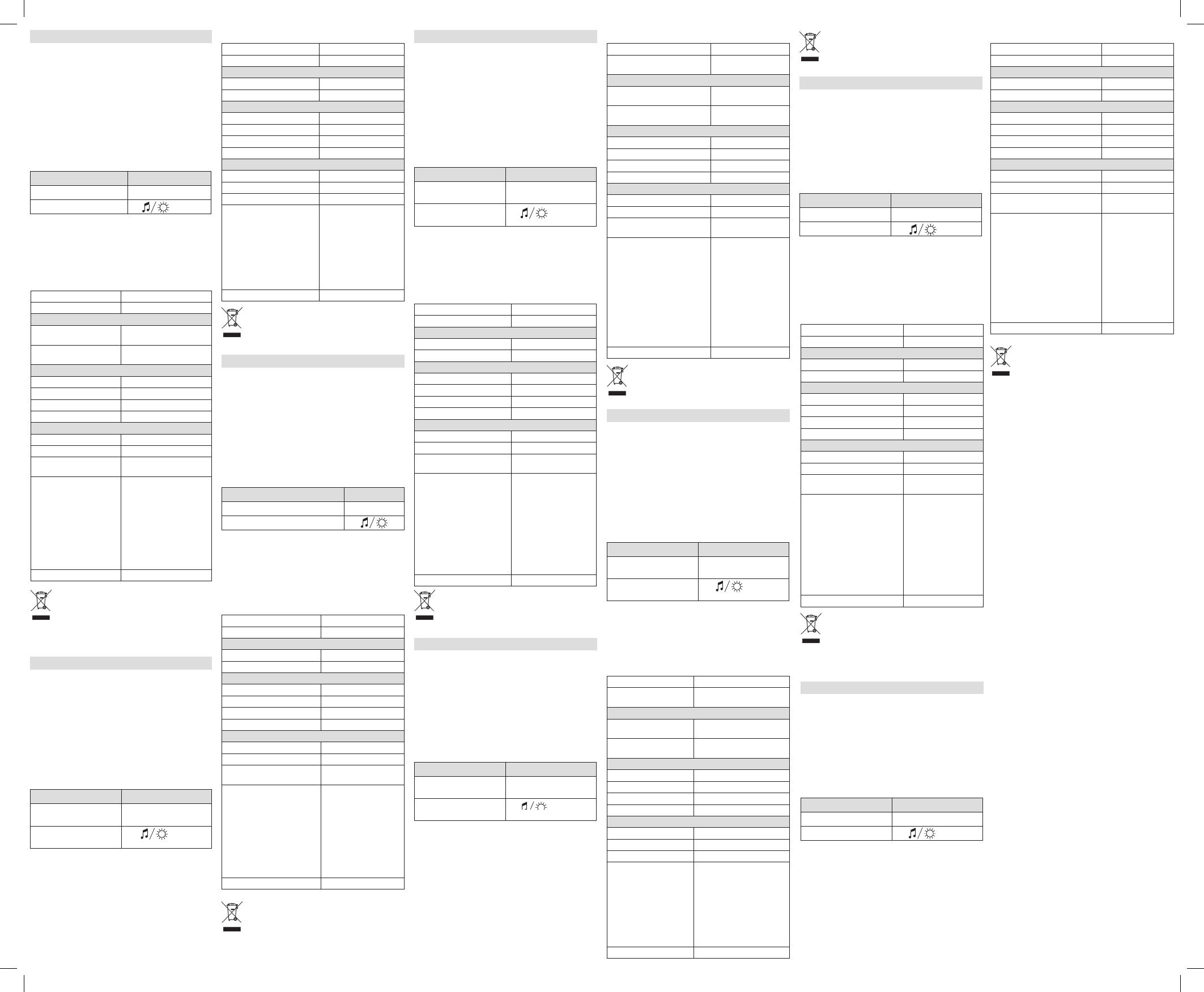
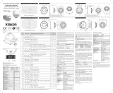
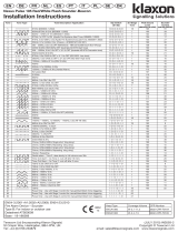
If required, the mechanism for locking the sounder to the base
can be activated by removing the thin section of plastic shown
in Fig. 1a with side cutters or a similar tool. To open a locked
head, remove the small rubber bung from the hole on the side
of the sounder, insert a tool into the hole and depress the clip
whilst twisting the head. The O-ring and bung must be re-fitted
to maintain the weatherproofing.
An alternative locking method is shown in Fig. 1b. Drive the
hexagonal locking screw forward by turning a 1.5mm hexagonal
key clockwise until the head is locked.
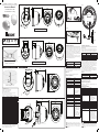
Wiring
Line Terminal Marking
Common Positive Supply IN (3) IN+
Beacon Negative Supply (1)
A separate earth terminal is provided on the deep base for connecting
the screen or functional earth. On the shallow base, terminal 5
can be used for this purpose.
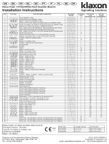
Flash rate
Switch 2 Flash rate: 0.5Hz =OFF/1Hz =ON (See Figure 2).
Technical Specification
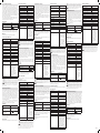
EN: Installation Manual
Instruction Manual
Sonos Pulse Beacon - Wall
Sonos Pulse Beacon - Ceiling
MADE IN ENGLAND INS560-3
Products marked with this symbol cannot be disposed of as
unsorted municipal waste in the European Union. For proper
recycling, return this product to your local supplier upon
the purchase of equivalent new equipment, or dispose of it
at designated collection points. For more information see:
www.recyclethis.info.
Supply Voltage Range 17- 60Vdc
Switch on Surge @ 24Vdc <1.2mA
Current:
Alarm (Beacon) @ 24Vdc 0.5Hz 20mA
Alarm (Beacon) @ 24Vdc 1Hz 40mA
Beacon:
Flash Rate
Light Temporal Pattern
• 55ms ON, 945mS OFF;
frequency ashing 1 second
(1Hz)
• 55ms ON, 1945mS OFF;
frequency ashing 2
seconds (0.5Hz)
Flash Colour White
Coverage (ceiling) C-3-15 (530m3)
Coverage (wall) W-3.1-11.3 (395.84m3)
Environmental:
Humidity 5% to 95%
Temperature -25°C to +70°C
Casing High Impact
Polycarbonate
IP Rating Type A-IP21C (shallow base)
Type B-IP33C (deep base) for
EN54-3,EN54-23 installations
with a cable gland (IP33C
minimum)
For other installations
independently tested to IP65
(IP65 is not valid on EN54-3
and EN54-23 installations).
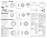
Synchronisation Automatic
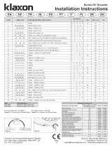
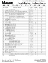
11.3m
11.3m
3.1m
Shallow Base/Base courte
FR: Notice d’instructions
EN54-23 Coverage: W-3.1-11.3
EN54-23 Coverage: C-3-15
Deep Base/Base profonde
Sonos Pulse Beacon - Ceiling/ Plafond Shallow Base/Base courte
Deep Base/Base profonde
Fig. 2
Fig. 1a
Klaxon Signals is a registered trademark of Texecom Ltd. © 2014
St. Crispin Way, Haslingden, BB4 4PW Tel: +44 1706 234800
Email: [email protected] www.klaxonsignals.com
Pulse Alert is a trademark of Texecom Ltd.
Pour activer le verrouillage de la sirène à sa base, il faut enlever
la fine plaque de plastique comme indiqué sur le dessin 1a avec
un cutter. Pour déverrouiller la base, enlever l’insert blanc situé
sur le côté, insérer un outil dans le trou pour appuyer sur le
verrou tout en faisant pivoter la sirène. Le joint torique et l’insert
doivent être replacé pour maintenir l’étanchéité.
Une autre méthode de blocage est indiquée à la gure 1b. Enler
la vis de blocage hexagonale en utilisant une clé hexagonale de
1.5 mm, et en la faisant tourner dans le sens des aiguilles d’une
montre jusqu’à ce que la tête soit bloquée.
Câblage
Alimentation Bornier
+ Alimentation (3) IN+
Feu à éclats- Alimentation (1)
Un terminal terre séparé est fourni sur la base profonde pour
connecter le câble ou terre fonctionnelle. Sur la base courte, le
terminal 5 peut être utilise a cet effet.
Fréquence de clignotement
L’interrupteur 2 Fréquence de clignotement: 0.5Hz =OFF/
1Hz =ON (voir figure 2).
Spécification technique
Tension admissible 17- 60Vdc
Switch on Surge @ 24Vdc <1.2mA
Courant:
Alarme (Feu à éclats) @ 24Vdc 0.5Hz 20mA
Alarme (Feu à éclats) @ 24Vdc 1Hz 40mA
Feu à éclats:
Fréquence de clignotement
Durée de l’impulsion lumineuse
• 55ms ON, 945mS OFF;
fréquence du clignotement 1
seconde (1Hz)
• 55ms ON, 1945mS OFF;
fréquence du clignotement 2
secondes (0.5Hz)
Couleur du ash Blanc
Couverture (plafond) C-3-15 (530m3)
Couverture (muraux) W-3.1-11.3 (395.84m3)
Environnementale:
Hygrométrique 5% to 95%
Température -25°C to +70°C
Matière Polycarbonate résistant
au choc
Degré d’étanchéité Type A IP21C (base courte),
Type B pour les installations
EN54-3, EN54-23 IP33C (base
profonde) avec un presse-
étoupe IP33C minimum.
Indépendamment testé à
IP65 pour toutes autres types
d’installation (IP65 non valide
sur les installations EN54-3 et
EN54-23).
Synchronisation Automatique
Les produits marqués de ce symbole peuvent pas être éliminés
comme déchets municipaux non triés dans l’Union européenne.
Pour le recyclage, retourner ce produit à votre fournisseur au
moment de l’achat d’un nouvel équipement équivalent, ou à
des points de collecte désignés. Pour plus d’informations, voir:
www.recyclethis.info.
=0.5Hz
=1Hz
Fire Alarm Device: Beacon.
Type A: For indoor use (Shallow Base)
Type B: For outdoor use (Deep Base)
Technical Datatsheet ATS00001
Essential Characteristics EN54-23:2010 Subclause
Duration of operation Pass
Provision for external conductors Pass
Flammability of materials Pass
Enclosure protection Pass
Access Pass
Manufacturers adjustments Pass
On-site adjustment behaviour Pass
Requirements for software controlled devices Pass
Coverage volume Pass
Variation of light output Pass
Minimum and maximum light intensity Pass
Light Colour White
Light temporal pattern and frequency of ashing Pass 0.5Hz/1Hz
Marking and data Pass
Synchronisation (Option with requirements) Pass
Durability Pass
Temperature Resistance Pass
Humidity resistance Pass
Shock and vibration resistance Pass
Corrosion resistance Pass
Electrical stability Pass
Fig. 1b
EN FR DE NL ES PT IT PL SE DK
Head Type Coverage Volume CPR Number LPCB Number
ESBA3000R C-3-15 0832-CPR-F0007 717e/01
ESBA3000W C-3-15 0832-CPR-F0007 717e/02
ESBA4000R W-3.1-11.3 0832-CPR-F0009 717e/03
ESBA4000W W-3.1-11.3 0832-CPR-F0009 717e/04
Certification NF
Seules les modèles avec une des références commerciales
suivantes sur leur tête et ayant l’estampille NF sont certifiées NF:
Conditions spéciales pour une utilisation avec un système NF-SSI:
No identification NF-SSI Référence commerciale
(Head Type)
Description
DL 020 A ESBA3000R C-3-15 Corps rouge
DL 020 B ESBA3000W C-3-15 Corps blanc
DL 020 C ESBA4000R W-3.1-11.3 Corps rouge
DL 020 D ESBA4000W W-3.1-11.3 Corps blanc
La tête doit être verrouillée à la base comme indiqué dans Fig1a.
0832
13 717e
FR: Dispositif visuel d’alarme feu avec diuseur sonore d’alarme feu
Type A : pour une utilisation intérieure (base courte).
Type B: Pour utilisation externe (base profonde). Fiche technique ATS00001
30
19
39
117
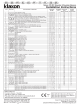
M20 drill out gland hole
for side cable entry
51
60
4.5mm Fixing Holes
M20 Drill out gland hole
for rear cable entry
97.5
102
103.5
100
14
94
51
60
Cable Entry
4.2 Fixing Holes
14
100
51
60
Cable Entry
4.2 Fixing Holes
100
19
39
122
M20 Drill out
gland hole for
side cable entry
51
60
30
4.5mm Fixing Holes
M20 Drill out
gland hole for
rear cable entry
97.5
EN: Ensure the lens of the device is pointing to the oor.
FR: Assurez-vous que la lentille est dirigée vers le sol.
EN: Ensure the lens of the device is pointing to the oor.
FR: Assurez-vous que la lentille est dirigée vers le sol.
M4
M20
M4
M20
M4
M4 M20
M20
INS560-3
Um den Signalgeber im Sockel zu arretieren, ist das
Sicherungsplättchen im Gehäuse zu entfernen. Dies kann
vorsichtig mit einem Seitenschneider oder ähnlichem Werkzeug,
wie in der Abb. 1a dargestellt, herausgelöst werden. Um einen
arretierten Signalgeberkopf aus dem Sockel zu entnehmen, ist
zunächst die weiße Schutzkappe am Kopf herauszuziehen und
durch die Öffnung, mit einem schmalen Schraubendreher, den
innen liegenden Verschlussbügel aus der Arretierungsposition
zu drücken. Um die Schutzklasse zu erhalten, ist die Schutzkappe
und der O-Ring wieder einzusetzen.
Abb. 1b zeigt eine alternative Verriegelungsmethode. Ziehen Sie
die Innensechskant-Feststellschraube durch Drehen eines 1.5
mm Sechskantschlüssels im Uhrzeigersinn fest.
Verdrahtung
Anschluss Klemme
Common Versorgung (3) IN+
Optisches Signal: Versorgung - 0V (1)
Eine zusätzliche Klemme steht im PG-Sockel zur Verfügung,
um PE oder die Abschirmung auflegen zu können. Im flachen
Montagesockel kann Klemme 5 zu diesem Zweck genutzt werden.
Blitzrate
Schalten 2 Blitzrate: 0.5Hz =Aus/1Hz =Ein (Siehe Abb. 2).
Technische Spezifikationen
DE: Installationsanweisung
Das Ziel der EG-Richtlinie über Elektro- und Elektronik-Altgeräte ist,
Umwelt- und Gesundheitsschäden durch Elektro- und Elektronik-
Altgeräte so gering wie möglich zu halten. Um diese Richtlinie
einzuhalten, dürfen Elektrogeräte, die mit diesem Symbol
gekennzeichnet sind, nicht in den öffentlichen europäischen
Entsorgungssystemen entsorgt werden. Europäische Benutzer von
Elektrogeräten müssen ab sofort Altgeräte zur Entsorgung zurückgeben.
Nähere Informationen hierzu finden Sie auf der folgenden Website:
www.recyclethis.info.
Betriebsspannung 17- 60Vdc
Einschaltspitze @ 24Vdc <1.2mA
Stromaufnahme:
Alarm (Warnleuchte) @ 24Vdc
0.5Hz
20mA
Alarm (Warnleuchte) @
24Vdc 1Hz
40mA
Warnleuchte:
Blitzrate 0.5Hz/1Hz
Blitzfarbe weiß
Wirkbereich (höchstgrenze) C-3-15 (530m3)
Wirkbereich (wand) W-3.1-11.3 (395.84m3)
Umgebungsbedingungen:
Relative Feuchte 5% bis 95%
Betriebstemperatur -25°C bis +70°C
Gehäuse Schlagbeständiges
Polykarbonat
Schutzklasse Typ A-IP21C (acher Sockel)
Typ B-IP33C (tiefer Sockel)
für EN54-3 und EN54-23
Installationen mit einer
Kabelverschraubung
(mindestens IP33C)
Für sonstige, unabhängig
gemäß IP65 geprüfte
Installationen (IP65 gilt nicht
für EN54-3 und EN54-23
Installationen).
Synchronisierung Automatisch
Indien nodig kan het mechanisme om het waarschuwingsbaken
aan de basis te vergrendelen worden geactiveerd door het
verwijderen van het dunne stukje plastic met een tang of
vergelijkbaar gereedschap zoals aangegeven in Fig. 1a. Om een
vergrendelde kop te openen: verwijder de kleine witte stop uit
het gat aan de zijkant van het alarm, steek een schroevendraaier
o.i.d. in het gat en druk het lipje in terwijl u de kop draait.
De o-ring en de stop moeten worden teruggeplaatst om de
waterdichtheid te behouden.
In Fig. 1b wordt een alternatieve vergrendelingsmethode
getoond. Draai de zeskantborgschroef met een 1.5 mm
zeskantsleutel naar rechts tot de kop is vergrendeld.
Bedrading
Lijn Contact markering
Common Gewone positieve
voeding
(3) IN+
Negatieve voeding waa
schuwingsbaken
(1)
Op de hoge basis is een aparte aardaansluiting aanwezig voor het
aansluiten van het schermof de aarde. Op de lage basis kan uitgang
5 hiervoor gebruiktworden.
Flitssnelheid
Met dipschakelaar 2 Flitssnelheid: 0.5Hz =UIT/1Hz =OP (zie afb. 2).
NL: Montageinstructies
Producten met deze label mogen niet verwijdert worden via de
gemeentelijke huisvuilscheiding in de Europese Gemeenschap.
Voor correcte vorm van kringloop, geef je de producten terug aan
jou locale leverancier tijdens het aankopen van een gelijkaardige
nieuw toestel, of geef het af aan een gespecialiseerde verzamelpunt.
Meer informatie vindt u op de volgende website: www.recyclethis.info.
Spanningsbereik 17- 60Vdc
Piek bij inschakelen @ 24Vdc <1.2mA
Stroomsterkte:
Alarm (Flitslicht) @ 24Vdc 0.5Hz 20mA
Alarm (Flitslicht) @ 24Vdc 1Hz 40mA
Flitslicht:
Flitssnelheid 0.5Hz/1Hz
Flash Kleur Wit
Dekkingsgebied (plafond) C-3-15 (530m3)
Dekkingsgebied (wand) W-3.5-11.5 (395.84m3)
Milieu-:
Relatieve vochtigheid 5% tot 95%
Gebruikstemperatuur -25°C tot +70°C
Behuizing Slagvast polycarbonaat
IP waarde Type A-IP21C (lage basis)
Type B-IP33C (diepe basis)
voor EN54-3, EN54-23
installaties met een
kabelbus (minimaal IP33C)
Voor andere installaties
onafhankelijk getest
voor IP65 (IP65 geldt niet
voor EN54-3 of EN54-23
installaties).
Synchronisatie Automatisch
Technische Specificaties
ES: Instrucciones de Instalación
PT: Manual de Instalação
IT: Istruzioni di installazione
PL: Instrukcja montażu
SE: Installationsmanual
DK: Installationsanvisninger
Active el mecanismo de seguridad si esto fuera necesario, para
evitar que la sirena pueda ser desconectada de la base. Para hacer
esto, corte el cacho de plástico que le mostramos en la Fig. 1a.
Una sirena que haya sido bloqueada, solo se puede desbloquear
quitando el pequeño tapón situado en el lateral e insertando
una pequeña varilla para presionar el mecanismo de bloqueo.
Debemos asegurar que la arandela y el tapón están colocados
para asegurar la resistencia a intemperie.
La Fig. 1b muestra un método de sujeción alternativo. Mueva
el tornillo de sujeción hexagonal hacia delante girando la llave
hexagonal de 1.5 mm en sentido horario hasta que la cabeza
quede jada.
Cableado
Línea Terminal
Common Positivo IN (3) IN+
Conexión Negativo de la luz de Xenón (1)
Se proporciona un terminal de tierra en la base profunda para
conectar el cable apantallado o funcional de tierra. En la base
superficial, el terminal 5 también se usa para esto.
Número de Destellos
Interruptor 2 Número de Destellos: 0.5Hz =OFF/1Hz =ON
(véase la figura 2).
Especificaciones Técnicas
Voltaje de Alimentación 17- 60Vdc
Encienda sobretensiones @ 24Vdc <1.2mA
Consumo:
Alarma (Beacon) @ 24Vdc 0.5Hz 20mA
Alarma (Beacon) @ 24Vdc 1Hz 40mA
Beacon:
Número de Destellos 0.5Hz/1Hz
Flash de Color Blanco
Cobertura (techo) C-3-15 (530m3)
Cobertura (pared) W-3.1-11.3 (395.84m3)
Medioambiental:
Humedad 5% a 95%
Temperatura -25°C a +70°C
Carcasa Policarbonato
Resistente al Fuego
Clasicación IP Tipo A-IP21C (base
supercial)
Tipo B-IP33C (base profunda)
para instalaciones EN54-3,
EN54-23 con prensaestopas
(mínimo IP33C)
Para otras instalaciones, pro-
bado independientemente
para IP65 (IP65 no es válido
en instalaciones EN54-3 o
EN54-23).
Sincronización Automática
El objetivo de la directiva europea de Eliminación de equipos
eléctricos y electrónicos (WEEE) es minimizar el impacto de la
eliminación de equipos eléctricos y electrónicos sobre el
medioambiente y la salud de las personas. Para cumplir con esta
directiva, el equipamiento eléctrico marcado con este símbolo no
deberá desecharse en ningún sistema de eliminación europeo público. Los
usuarios europeos de equipamiento eléctrico deberán retornar los equipos
eléctricos y electrónicos al final de su vida útil para su eliminación. Para más
información visite el siguiente sitio Web: www.recyclethis.info.
Se necessário, o mecanismo para fixar o sensor à base pode ser
activado removendo a fina película de plástico ilustrada na Fig.
1a com um alicate de corte ou uma ferramenta semelhante. Para
abrir uma cabeça bloqueada, retire o pequeno tampão branco do
orifício existente na parte lateral do sensor, insira uma ferramenta
no orifício e carregue na mola enquanto roda a cabeça. O O-ring
e o tampão devem ser reinstalados no intuito de manter a
estanquicidade às intempéries.
Na Fig. 1b é apresentado um método de bloqueio alternativo.
Avance o parafuso de bloqueio hexagonal ao rodar uma chave
hexagonal de 1.5 mm no sentido dos ponteiros do relógio até ao
bloqueio da cabeça.
Gama da tensão de alimentação 17- 60Vdc
Surto de ligação @ 24Vdc <1.2mA
Corrent:
Alarme (luminoso) @ 24Vdc 0.5Hz 20mA
Alarme (luminoso) @ 24Vdc 1Hz 40mA
Luminoso:
Alimentação 0.5Hz/1Hz
Flash de cor Branco
Cobertura (teto) C-3-15 (530m3)
Cobertura (parede) W-3.1-11.3 (395.84m3)
Ambiental:
Umidade relativa 5% a 95%
Temperatura -25°C a +70°C
Caixa Policarbonato de
alto impacto
Classe de protecção Tipo A-IP21C (base
côncava)
Tipo B-IP33C (base
profunda) para instalações
EN54-3, EN54-23 com
boquilha de cablagem
(mínimo IP33C)
Para outras instalações
testadas individualmente
para IP65 (IP65 não é válido
em instalações EN54-3 e
EN54-23).
Sincronização Automático
Produtos marcados com este símbolo não podem ser eliminados
como resíduos urbanos indiferenciados na União Europeia. Para
proceder à reciclagem adequada, devolva este produto ao seu
fornecedor local na compra de novo equipamento equivalente, ou
entregue-o nos pontos de recolha designados para o efeito. Para
mais informações, ver www.recyclethis.info.
W razie potrzeby mechanizm blokujący głośnik na podstawie
można uruchomić, usuwając cienką warstwę folii pokazaną
na Rys. 1a za pomocą szczypiec lub podobnego narzędzia.
Aby otworzyć zablokowaną głowicę, należy usunąć małe, białe
zamknięcie z otworu bocznego głośnika i za pomocą narzędzia
umieszczonego w otworze nacisnąć zatrzask jednocześnie
przekręcając głowicę. Pierścień „O” i zamknięcie muszą zostać
założone ponownie, aby zapewnić zabezpieczenie przed
warunkami pogodowymi.
Inną metodę blokowania przedstawiono na rysunku 1b. Obróć
w prawo sześciokątną śrubę blokującą za pomocą klucza
sześciokątnego 1.5 mm aż do zablokowania głowicy.
Okablowanie
Linia Listwa zaciskowa
Dodatnie, normalne
zasilanie wejściowe IN
(3) IN+
Ujemne zasilanie
sygnalizatora
(1)
W głębokiej podstawie dostępna jest oddzielna listwa zaciskowa
dla podłączenia ekranu lub zera roboczego. W przypadku płytkiej
podstawy do tego celu służy zacisk 5.
Częstotliwość migania
Przełącznik 2 Częstotliwość migania: 0.5Hz =Poza/1Hz =Na (Rys. 2).
Dane techniczne
Zakres napięcia 17- 60Vdc
Prąd udarowy przy włączeniu
@ 24Vdc
<1.2mA
Prąd:
Alarm (sygnalizator optyczny)
@ 24Vdc 0.5Hz
20mA
Alarm (sygnalizator optyczny)
@ 24Vdc 1Hz
40mA
Sygnalizator optyczny:
Częstotliwość migania 0.5Hz/1Hz
Flash Kolor biały
Pokrycie (sut) C-3-15 (530m3)
Pokrycie (wall) W-3.1-11.3 (395.84m3)
środowiskowy:
Wilgotność względna 5% do 95%
Temperatura -25°C do +70°C
Obudowa Wytrzymałego poliwęglanu
Oznaczenie IP Typ A-IP21C (płytka podstawa)
Typ B-IP33C (głęboka pod-
stawa) w przypadku instalacji
EN54-3, EN54-23 z dławnicą
kablową (minimum IP33C)
W przypadku innych instalacji
testowanych niezależnie
pod kątem IP65 (IP65 nie
obowiązuje w przypadku insta-
lacji EN54-3 i EN54-23).
Synchronizacja Automatyczna
W Unii Europejskiej produkty oznaczone tym symbolem mogą
być usuwane tylko jako posegregowane odpady komunalne. Dla
zapewnienia właściwej utylizacji, należy zwrócić ten produkt do
dostawcy przy zakupie ekwiwalentnego, nowego urządzenia albo
dostarczyć go do wyznaczonego punktu zbiórki. Więcej informacji
można znaleźć na stronie internetowej www.recyclethis.info.
Om så behövs, kan mekanismen för att låsa summern vid basen
aktiveras genom att avlägsna den tunna plastbiten, såsom visas
i Fig. 1a, med en sidavbitare eller liknande. För att öppna ett låst
huvud, avlägsna den lilla vita proppen från hålet på sidan av
summern, för in ett verktyg i hålet och tryck ned klämman medan
huvudet vrids. O-ringen och proppen måste sättas tillbaka för att
bibehålla väderskyddet.
En alternativ låsmetod visas i Fig. 1b. Driv den sexkantiga
låsskruven framåt genom att vrida en 1.5 mm insexnyckel
medsols tills huvudet är låst.
Koppling
Lina Klämma
Gemensamt positivt nät (3) IN+
Blinkljus negativt nät (1)
En separat jordklämma finns på den djupa basen för att anslutas
till skärmen eller funktionsjord. På den låga basen, kan klämma 5
användas för detta ändamål.
Blinkhastighet
Strömbrytare 2 Blinkhastighet: 0.5Hz =Av/1Hz =På (Se Figur 2).
Matningsspänningsområde 17- 60V likström
Slå på Surge @ 24Vdc <1.2mA
Ström:
Alarm (Blinkljus) @ 24Vdc 0.5Hz 20mA
Alarm (Blinkljus) @ 24Vdc 1Hz 40mA
Blinkljus:
Blinkhastighet 0.5Hz/1Hz
Flash Färg Vit
Täckning (tak) C-3-15 (530m3)
Täckning (vägg) W-3.1-11.3 (395.84m3)
Miljö:
Luftfuktighet 5% a 95%
Arbetstemperatur -25°C a +70°C
Hus Hus av extra slagtåligt
polykarbonat
IP-värde Typ A-IP21C (grund bas)
Typ B-IP33C (djup bas)
för installationerna
EN54-3, EN54-23 med en
kabelpackbox (minimalt
IP33C)
För övriga installationer
som fristående testats
enligt IP65 (IP65 är inte
giltig på installationerna
EN54-3 och/eller
EN54-23).
Synkronisering Automatisk
Det europeiska direktivet om avfall som utgörs av eller innehåller
elektriska eller elektroniska produkter (WEEE) har i syfte att
minimera verkningen av elektriskt och elektroniskt avfall på miljö
och människors hälsa. För att följa detta direktiv, får elektrisk
utrustning märkt med denna symbol inte avfallshanteras i europeiska
kommunala avfallssystem. Europeiska brukare av elektrisk utrustning måste
numera lämna tillbaka uttjänad utrustning för avfallshantering. Ytterligare
information finns på följande hemsida: www.recyclethis.info.
Se necessario, è possibile attivare il meccanismo di bloccaggio
del segnalatore luminoso alla base rimuovendo la sottile
linguetta di plastica illustrata nella Fig. 1a con un tronchesino
o un attrezzo simile. Per aprire una testina bloccata, rimuovere
il piccolo tappo bianco dal foro laterale del segnalatore acustico,
inserire un attrezzo nel foro e premere il fermo svitando la testina.
La guarnizione ad anello e il tappo devono essere riposizionati
per mantenere la resistenza alle intemperie.
La Fig. 1b mostra un metodo di bloccaggio alternativo. Serrare la
vite di bloccaggio esagonale ruotando una chiave esagonale da
1.5 mm no al bloccaggio della testa.
Cablaggio
Linea Contrassegno sui terminali
IN alimentazione positiva
comune
(3) IN+
Alimentazione negativa
segnalatore luminoso
(1)
La base profonda è dotata di un terminale di terra separato per il
collegamento dello schermo o della terra funzionale. Sulla base
superficiale, allo stesso scopo è possibile usare il terminale 5.
Velocità del flash
Interruttore 2 Velocità del flash: 0.5Hz =Spento/1Hz =Acceso
(vedere figura 2).
Gamma tensione di alimentazione 17- 60Vdc
Sovracorrente all’accensione @
24Vdc
<1.2mA
Corrente:
Allarme (lampeggiante) @ 24Vdc
0.5Hz
20mA
Allarme (lampeggiante) @ 24Vdc
1Hz
40mA
Lampeggiante:
Velocità del ash 0.5Hz/1Hz
Flash di colore Bianco
Copertura (sotto) C-3-15 (530m3)
Copertura (muro) W-3.1-11.3 (395.84m3)
Ambientale:
Umidità relativa 5% a 95%
Temperatura -25°C a +70°C
Alloggiamento Policarbonato ad alto
impatto
Classe di IP Tipo A-IP21C (base
superciale)
Tipo B-IP33C (base
profonda) per instal-
lazioni EN54-3 e EN54-23
con passacavo (minimo
IP33C)
Per altre installazioni
testate in modo indip-
endente per IP65 (IP65
non è valida per le
installazioni EN54-3 e
EN54-23).
Sincronizzazione Automatica
I prodotti contrassegnati con questo simbolo, non possono essere
smaltiti nei comuni contenitori per lo smaltimento rifiuti, nell’Unione
Europea. Per il loro corretto smaltimento, potete restituirli al vostro
fornitore locale a seguito dell’acquisto di un prodotto nuovo
equivalente, oppure rivolgervi e consegnarli presso i centri di
raccolta preposti. Per maggiori informazioni vedere: ww.recyclethis.info.
Om nødvendigt kan mekanismen for aflåsning af lyd alarmen
til underlaget aktiveres ved at fjerne det tynde plastik lag,
som vist på fig. 1a; dette kan gøres med sideskærere eller et
lignende værktøj. For at åbne et låst hoved, fjern den lille hvide
spunstap fra hullet på lyd alarmens side, og sæt et værktøj ind
i hullet og tryk klemmen ned mens hovedet drejes. O-ringen
og spunstappen skal genmonteres for at bevare vejrtætningen.
En alternativ låsemetode er vist i Fig. 1b. Før den sekskantede
låseskrue fremad ved at dreje en 1.5mm sekskantet indstiksnøgle
med uret, indtil hovedet er låst fast.
Trådføring
Ledning Klemme
Gemensamt positivt nät (3) IN+
Blinkljus negativt nät (1)
Der findes en separat jordklemme på det dybe underlag for tilslutning
af skærmen eller den funktionelle jordklemme. På det flade underlag,
kan klemme 5 bruges til dette formål.
Blinkfrekvens
Kontakt 2 Blinkfrekvens: 0.5Hz =Fra/1Hz =Til (Se figur 2).
Strømforsyningens spændingsområde 17- 60Vdc
Tænd Surge @ 24Vdc <1.2mA
Strøm:
Alarm (Blinklys) @ 24Vdc 0.5Hz 20mA
Alarm (Blinklys) @ 24Vdc 1Hz 40mA
Blinklys:
Blinkfrekvens 0.5Hz/1Hz
Blitz Farve Hvid
Dækning (loft) C-3-15 (530m3)
Dækning (væg) W-3.1-11.3 (395.84m3)
Miljø:
Fugtighed 5% til 95%
Driftstemperatur -25°C til +70°C
Hus Slagfast hus af polykar-
bonat
IP kapacitet Type A-IP21C (smal
sokkel)
Type B-IP33C (bred
sokkel) til EN54-3,
EN54-23 installationer
med en kabelforskrun-
ing (minimum IP33C)
Til andre installationer
uafhængigt afprøvet
til IP65 (IP65 er ikke
gyldig på EN54-3 eller
på EN54-23 instal-
lationer).
Synkronisering Automatisk
Det europæiske direktiv “Waste Electrical and Electronic Equipment”
(WEEE) satser på at reducere påvirkningen af affald fra elektrisk
og elektronisk udstyr på miljøet og menneskers sundhed. For at
overholde dette direktiv, må elektrisk udstyr med dette symbol
ikke kasseres i offentlige europæiske affaldssystemer. Europæiske
brugere af elektrisk udstyr skal returnere udtjent udstyr for kassering.
Yderligere information findes på følgende webside: www.recyclethis.info.
Cablagem
linha Marcação Terminal
Alimentação positiva
comum IN
(3) IN+
Alimentação negativa do
farolim rotativo
(1)
É fornecido um terminal terra independente na base profunda para
ligar o ecrã ou a terra funcional. Na base côncava, pode utilizar-se o
terminal 5 para este fim.
Alimentação
Interruptor 2 Alimentação: 0.5Hz =OFF/1Hz =ON (veja a Figura 2).
Especificações técnicas
Teknisk specifikation
Specifiche tecniche Teknisk specifikation
-
 1
1
-
 2
2


Klaxon Sonos Pulse Beacon Wall Instruções de operação
- Tipo
- Instruções de operação
em outras línguas
- español: Klaxon Sonos Pulse Beacon Wall Instrucciones de operación
- français: Klaxon Sonos Pulse Beacon Wall Mode d'emploi
- italiano: Klaxon Sonos Pulse Beacon Wall Istruzioni per l'uso
- Deutsch: Klaxon Sonos Pulse Beacon Wall Bedienungsanleitung
- dansk: Klaxon Sonos Pulse Beacon Wall Betjeningsvejledning
Artigos relacionados
-
 Klaxon Sonos Pulse Beacon Ceiling Instruções de operação
-
 Klaxon Sonos Pulse Sounder Beacon Wall Instruções de operação
-
 Klaxon Sonos Pulse Sounder Beacon Wall Instruções de operação
-
 Klaxon Nexus Pulse 105 & 110 Instruções de operação
-
 Klaxon Sonos Sounder Instruções de operação
-
 Klaxon Nexus Pulse 105 & 110 Instruções de operação
-
McQuay Smoke Alarm 110 AC Manual do usuário
-
 Klaxon 120 AC Manual do usuário
-
 Klaxon Nexus 105/110/120 Sounder Instruções de operação


