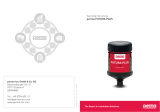
Alarm pull station - PH1
Technical manual

ii ALARM PULL STATION - PH1 TM230 Issue F July 2019 www.eaton.com
DISCLAIMER OF WARRANTIES AND LIMITATION OF LIABILITY
The information, recommendations, descriptions and safety notations in this document are based on Eaton Corporation’s
(“Eaton”) experience and judgment and may not cover all contingencies. If further information is required, an Eaton sales
office should be consulted. Sale of the product shown in this literature is subject to the terms and conditions outlined in
appropriate Eaton selling policies or other contractual agreement between Eaton and the purchaser.
THERE ARE NO UNDERSTANDINGS, AGREEMENTS, WARRANTIES, EXPRESSED OR IMPLIED, INCLUDING
WARRANTIES OF FITNESS FOR A PARTICULAR PURPOSE OR MERCHANTABILITY, OTHER THAN THOSE
SPECIFICALLY SET OUT IN ANY EXISTING CONTRACT BETWEEN THE PARTIES. ANY SUCH CONTRACT STATES THE
ENTIRE OBLIGATION OF EATON. THE CONTENTS OF THIS DOCUMENT SHALL NOT BECOME PART OF OR MODIFY
ANY CONTRACT BETWEEN THE PARTIES.
In no event will Eaton be responsible to the purchaser or user in contract, in tort (including negligence), strict liability or
other-wise for any special, indirect, incidental or consequential damage or loss whatsoever, including but not limited to
damage or loss of use of equipment, plant or power system, cost of capital, loss of power, additional expenses in the
use of existing power facilities, or claims against the purchaser or user by its customers resulting from the use of the
information, recommendations and descriptions contained herein. The information contained in this manual is subject to
change without notice.

iiiALARM PULL STATION - PH1 TM230 Issue F July 2019 www.eaton.com
Alarm pull station - PH1
English
iiiALARM PULL STATION - PH1 TM230 Issue F July 2019 www.eaton.com
Contents
1.0 INTRODUCTION ......................................................................1
2.0 GENERAL SAFETY MESSAGES AND WARNINGS . . . . . . . . . . . . . . . . . . . . . . . . . . . . . . . . . . . . . . . . . .1
3.0 INSTALLATION .......................................................................1
Access to terminals .......................................................................... 1
4.0 STANDARD WIRING OPTIONS ..........................................................2
5.0 OPERATION .........................................................................3
6.0 MAINTENANCE ......................................................................3
7.0 CERTIFICATION/APPROVALS ...........................................................3
lECEx units ................................................................................ 3
ATEX units ................................................................................. 4
8.0 SPECIAL CONDITIONS FOR SAFE USE ...................................................4
9.0 FUNCTIONAL SAFETY ................................................................4

iv ALARM PULL STATION - PH1 TM230 Issue F July 2019 www.eaton.com

1ALARM PULL STATION - PH1 TM230 Issue F July 2019 www.eaton.com
Alarm pull station - PH1
English
1.0 Introduction
These manual fire alarm pull stations have been designed
for use in hazardous locations and harsh environmental
conditions. The GRP enclosures are suitable for use
offshore or onshore where light weight combined with a
high level of corrosion resistance is required.
2.0 General safety messages and
warnings
All instructions and safety messages in this manual must
be followed to allow safe installation of the device. The
device must only be installed and maintained by correctly
trained site personnel/installers.
I. To reduce the risk of ignition of hazardous
atmospheres and shock, do not apply power to the
device until installation has been completed and the
device is fully sealed and secured.
II. To reduce the risk of ignition of hazardous
atmospheres and shock, keep device tightly closed
when the circuit is energised.
III. Before removing the cover for installation or
maintenance, ensure that the power to the device
isisolated.
IV. Following installation, test the device to ensure
correct operation.
V. Following installation ensure a copy of this manual is
made available to all operating personnel.
VI. When installing the device, requirements for
selection, installation and operation should be
referred to e.g. IEE Wiring Regulations and the
‘National Electrical Code’ in North America. Additional
national and/or local requirements may also apply.
VII. Cable termination should be in accordance with
specification applying to the required application.
MEDC recommends that all cables and cores should
be correctly identified. Please refer to the wiring
diagram in this manual (or separate diagram provided
with the unit).
VIII. Ensure that only the correct listed or certified cable
glands are used and that the assembly is shrouded
and correctly earthed.
IX. Ensure that only the correct listed or certified
stopping plugs are used to blank off unused gland
entry points and that the NEMA/IP rating of the unit
is maintained.
X. MEDC recommend the use of a sealing compound
such as HYLOMAR PL32 on the threads of all glands
and stopping plugs in order to maintain the IP rating
of the unit.
XI. The internal earth terminal, where fitted, must be
used for the equipment grounding and the external
terminal, if available, is for a supplementary bonding
connection where local codes or authorities permit or
require such a connection.
XII. When installing the device, MEDC recommends the
use of stainless steel fasteners. Ensure that all nuts,
bolts and fixings are secure.
XIII. The pull station should not be mounted closer than
40mm to any solid object which does not form part
of the unit.
XIV. When fitting or removing cable entry glands, the
cable entry inserts must be held with a suitable tool
to prevent movement.
3.0 Installation
The unit is mounted via 4 off Ø6.5mm fixing holes in the
base of the enclosure. The unit has been designed and
certified to operate at any attitude.
The fixing holes have been designed to accept an M6
screw or bolt.
Access to terminals
Unscrew the 4 off M6 screws (5.0mm A/F hexagon
key) holding the cover assembly to the base. The cover
screws are retained in the cover assembly for ease of
installation. Gently lift the cover assembly away from the
base of the enclosure to gain access to the interior.
Once termination is complete, carefully replace the cover
assembly back onto the base of the enclosure, avoiding
damage to the mating surfaces. Ensure the o-ring is
correctly seated in its groove during re-assembly. Evenly
tighten the 4 off M6 screws (5.0mm A/F hexagon key).
Ensure the required gap (0.10mm Max.) is maintained
between the cover and the base.

2 ALARM PULL STATION - PH1 TM230 Issue F July 2019 www.eaton.com
Alarm pull station - PH1
English
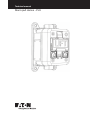
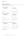
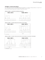
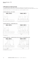
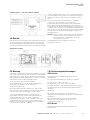
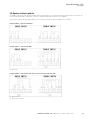
4.0 Standard wiring options
See below for the standard wiring options for the PH1. If a different wiring layout has been specified when ordering the
unit, please see the separate diagram supplied with the unit.
EOL resistors should only be fitted to the last unit in a system.
Standard wiring – switch only
Standard wiring – c/w EOL resistor
R1 – EOL resistor
Standard wiring – c/w series resistor or series & EOL resistors
R1 – Series resistor
R2 – EOL resistor (if fitted)

3ALARM PULL STATION - PH1 TM230 Issue F July 2019 www.eaton.com
Alarm pull station - PH1
English
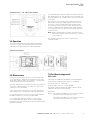
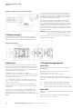
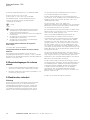
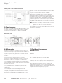
Standard wiring – c/w addressable module
5.0 Operation
The unit is operated by lifting the spring loaded flap
on the front of the unit, then pulling down the handle
underneath. The pull handle will rotate downwards
through 90 degrees. The pull handle will remain latched in
the operated position until manually reset. The lift flap can
be lowered back to its original position until the unit needs
to be reset.
The reset the unit, first raise the lift flap away from the
pull handle. The key (provided with the unit) is inserted
into the two holes located underneath the pull handle
in the front face until resistance is felt. Depress the key
further to release the pull handle which can be returned
to its original position. Finally, lower the lift flap back to its
original position.
ote:N When resetting the unit, please ensure the key is
depressed centrally with even pressure on each leg
of the reset key.
The operating voltage of the unit is stated on the
certification label.
General arrangement
6.0 Maintenance
During the working life of the unit, it should require little
or no maintenance. GRP will resist attack by most acids,
alkalis and chemicals and is as resistant to concentrated
acids and alkalis as most metal products.
However, if abnormal or unusual environmental conditions
occur due to plant damage or accident etc., then visual
inspection is recommended.
If the unit requires cleaning, then only clean the exterior
with a damp cloth to avoid electrostatic charge build up.
If a unit fault should occur, then the unit can be repaired
by MEDC. All parts of the unit are replaceable.
If you acquired a significant quantity of units, then it
is recommended that spares are also made available.
Please discuss your requirements with the Technical Sales
Engineers at MEDC.
7.0 Certification/approvals
lECEx units
Certified to IEC 60079-0, IEC 60079-1 and IEC 60079-31
Ex d unit (IEC certification No. IECEx ITS 11.0021X)
Ex d IIC T6 (-55°C to +70°C) Gb
Ex tb IIIC T85°C (-55°C to +70°C) Db IP66
The IECEx certificate and product label carry the IECEx
equipment protection level markings
Gb and Db
Where Gb signifies suitability for use in a Zone 1 surface
industries area in the presence of gas.
Db signifies suitability for use in a Zone 1 surface
industries area in the presence of dust.

4 ALARM PULL STATION - PH1 TM230 Issue F July 2019 www.eaton.com
Alarm pull station - PH1
English
ATEX units
Certified to EN 60079-0, EN 60079-1 and EN 60079-31
Ex d unit (ATEX certification No. ITS11ATEX17308X)
Ex d IIC T6 (-55°C to +70°C) Gb
Ex tb IIIC T85°C (-55°C to +7 0°C) Db IP66
The ATEX certificate and product label carry the ATEX
group and category marking:
II 2 GD
Where:
Signifies compliance with ATEX
II Signifies suitability for use in surface industries
2 Signifies suitability for use in a zone 1 area
G Signifies suitability for use in the presence of gases
D Signifies suitability for use in the presence of dust
These units also have the following approvals:
Ingress protection: IP67 to IEC60529
Temperature rating for units with addressable module:
These units have been certified as safe for use in an
ambient temperature range of (-55°C to +70°C) but
will be marked with the addressable module operating
temperature range (0°C to +49°C)
8.0 Special conditions for safe use
1. The threaded insert as supplied with the unit must
not be removed or replaced.
2. Potential electrostatic charging hazard – clean only
with a damp cloth.
9.0 Functional Safety
The PH1 double action pull handle call point has been
designed for use in flammable atmospheres and harsh
environmental conditions. The GRP enclosure is suitable
for use offshore or onshore where light weight combined
with a high level of corrosion resistance is required.
The function of the PH1 call point is to raise an alarm
manually once verification of a fire or emergency
conditions exists by operating the “LIFT” and “PULL”
handles.
The large “LIFT” and “PULL” GRP handles require double
action to raise the alarm, preventing accidental activation.
The safety function of the PH1 is to open a normally
closed contact (and close a normally open contact) upon
the “Pull” handle being pulled
Under no fault (normal) operating conditions when the
handle has not been pulled, the normally open contact
will be open circuit.
To activate the safety function, the “LIFT” flap will be
pulled upwards revealing the “PULL” handle, the “PULL”
handle can then be pulled downwards to activate the
internal switches. The “PULL” handle will be latched into
place to ensure that the switch stays actuated. The PH1
must then be reset manually by inserting a specific tool
into the two reset holes on the front of the device.
Under fault conditions the failure mode of the PH1 is
a failure to activate the internal switches resulting in a
failure to raise the alarm. For the failure rate associated
with this failure please refer to the table below
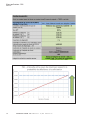
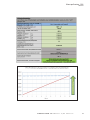
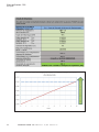
Assessment of Functional Safety
The PH1 Call Point is intended for use in a safety system
confirming to the requirements of IEC 61508. SIRA
has conducted a Failure Modes Effects and Diagnostic
Analysis (FMEDA) of the PH1 call point against the
requirements of IEC 61508-2 using a proof test interval of
8760 hours. The results are shown below and are based
on Route 1H
The PH1 is classed as a Type A device.

5ALARM PULL STATION - PH1 TM230 Issue F July 2019 www.eaton.com
Alarm pull station - PH1
English

6 ALARM PULL STATION - PH1 TM230 Issue F July 2019 www.eaton.com
Alarm pull station - PH1
English
Proof Testing
Proof testing is carried out by using the ‘LIFT’ and ‘PULL’
handles to activate the safety function as described above
and ensuring that the switch has been actuated. It should
also be checked that the switch has been returned to its
normal operating position after being manually reset as
described above.
Conditions of Safe Use
The following conditions apply to the installation,
operation and maintenance of the PH1 call point. Failure
to observe these may compromise the safety integrity of
the assessed equipment.
1. The user shall comply with the requirement
given in this Safety Manual and Technical Manual
regarding all relevant functional safety aspects such as
application of use, installation, operation, maintenance,
proof tests, maximum ratings, environmental conditions,
repair, etc.
2. Selection of this equipment for use in safety
functions and the installation, configuration, overall
validation, maintenance and repair shall only be
carried out by competent personnel, observing all the
manufacturer’s conditions and recommendations in the
user documentation
3. All information associated with any field
failures of this product should be collected under a
dependability management process (e.g. IEC 60300-3-
2) and reported to the manufacturer.
4. The unit should be tested at regular intervals to
identify any malfunctions; in accordance with this safety
manual

7ALARM PULL STATION - PH1 TM230 Issue F July 2019 www.eaton.com
Alarm pull station - PH1
Francais
Contents
1.0 INTRODUCTION ......................................................................8
2.0 MESSAGES ET AVERTISSEMENTS GÉNÉRAUX DE SÉCURITÉ . . . . . . . . . . . . . . . . . . . . . . . . . . . . . . .8
3.0 INSTALLATION .......................................................................8
Accès aux bornes ........................................................................... 8
4.0 OPTIONS STANDARD DE CÂBLAGE .....................................................9
5.0 FONCTIONNEMENT .................................................................10
6.0 ENTRETIEN ........................................................................10
7.0 CERTIFICATION/APPROBATIONS .......................................................10
Unités lECEx .............................................................................. 10
Unités ATEX ................................................................................11
8.0 CONDITIONS SPÉCIALES POUR UTILISATION SÉCURISÉE .................................11

8 ALARM PULL STATION - PH1 TM230 Issue F July 2019 www.eaton.com
Alarm pull station - PH1
Francais
1.0 Introduction
Ces dispositifs d’alarme-incendie manuels sont conçus
pour une utilisation en zones dangereuses et dans des
conditions environnementales sévères. Les boîtiers GRP
sont adaptés à une utilisation off-shore ou on-shore, où un
poids léger et un haut niveau de résistance à la corrosion
sont nécessaires.
2.0 Messages et avertissements
généraux de sécurité
Suivre toutes les instructions et messages de sécurité
contenus dans ce manuel pour permettre l’installation
sécurisée de l’appareil. L’appareil doit être exclusivement
installé et entretenu par du personnel/des installateurs sur
site proprement formés.
I. Pour réduire le risque d’incendie dans des
atmosphères dangereuses et de décharges, ne pas
mettre l’appareil sous tension avant d’avoir terminer
l’installation et avant de l’avoir parfaitement scellé
etsécurisé.
II. Pour réduire le risque d’incendie dans des
atmosphères dangereuses et de décharges, maintenir
l’appareil totalement fermé lors de la mise sous
tension du circuit.
III. Avant de retirer le couvercle pour toute opération
d’installation ou d’entretien, s’assurer que
l’alimentation de l’appareil est isolée.
IV. Une fois l’installation terminée, tester l’appareil pour
s’assurer de son bon fonctionnement.
V. Une fois l’installation terminée, s’assurer qu’une
copie de ce manuel est mise à la disposition de tous
les opérateurs.
VI. Lors de l’installation de l’appareil, se reporter
aux exigences de sélection, d’installation et de
fonctionnement : aux Réglementations de câblage de
l’IEE et au code national d’électricité américain (NEC)
pour l’Amérique du Nord, par exemple. Des exigences
nationales et/ou locales supplémentaires peuvent
également s’appliquer.
VII. Les terminaisons de câble doivent être conformes
aux exigences spécifiques de l’application requise.
MEDC recommande que tous les câbles et
conducteurs soient correctement identifiés. Merci
de se reporter au schéma de câblage fourni dans ce
manuel (ou au schéma spécifique fourni avec l’unité).
VIII. S’assurer de n’utiliser que les presses étoupes
spécifiées ou certifiées, et du bon revêtement et
mise à la terre de l’assemblage.
IX. S’assurer de n’utiliser que les bouchons obturateurs
spécifiés ou certifiés pour obturer les entrée de
presses étoupes non utilisées, et que les normes
NEMA/de protection IP de l’unité sont maintenues.
X. MEDC recommande l’utilisation d’une pâte
d’étanchéité telle que HYLOMAR PL32 sur tous
les filetages des presses étoupes et des bouchons
obturateurs, afin de maintenir les normes de
protection IP de l’unité.
XI. La borne de masse interne, si l’unité en est
équipée, doit être utilisée pour la mise à la terre
de l’équipement, et la borne externe, si disponible,
constitue une fixation supplémentaire à la borne
de terre lorsque les normes ou autoritées locales
permettent ou exigent une telle connexion.
XII. MEDC recommande l’utilisation d’éléments de
fixation en acier inoxydable lors de l’installation de
l’appareil. S’assurer que tous les écrous, les boulons
et les fixations sont sécurisés.
XIII. Le dispositif d’alarme ne doit pas être monté à moins
de 40 mm de tout objet solide n’appartenant pas
àl’unité.
XIV. Lors de l’installation ou de retrait des presse-étoupe
des entrées de câbles, les insertions d’entrée de
câble doivent être tenues à l’aide d’un outil adapté
pour éviter tout mouvement.
3.0 Installation
L’unité se monte via 4 trous de fixation de Ø6,5 mm
situés sur le socle du boîtier. L’unité a été conçue, et est
certifiée, pour fonctionner en tout mode.
Les trous de fixation de la plaque arrière ont été conçus
pour accueillir une vis ou un boulon M6.
Accès aux bornes
Dévisser les 4 vis non imperdables M6 (à l’aide d’une
clé hexagonale/à 6 pans de 5 mm) qui fixent le couvercle
au socle. Les vis ne se dégageront pas du couvercle,
ce qui facilite l’installation. Soulever doucement le
couvercle pour le dégager du socle du boîtier et accéder
à l’intérieur de la boîte.
Une fois l’opération de terminaison des câbles terminée,
remettre le couvercle en place sur le socle du le boîtier
en faisant attention à ne pas endommager les surfaces
de contact. S’assurer que le joint torique est bien
positionné dans son logement lors du remontage. Serrer
uniformément les 4 vis non imperdables M6 (à l’aide
d’une clé hexagonale/à 6 pans de 5 mm). S’assurer que
l’écart requis (0,10 mm max.) est maintenu entre le
couvercle et le socle.

9ALARM PULL STATION - PH1 TM230 Issue F July 2019 www.eaton.com
Alarm pull station - PH1
Francais
4.0 Options standard de câblage
Voir ci-dessous pour les options standard de câblage de l’unité PH1. Si un schéma de câblage différent a été spécifié lors
de la commande de l’unité, merci de se référer schéma séparé fourni avec l’unité.
Ne monter des résistances EOL que sur le dernier module d’un système.
Câblage standard – commutateur d’allumage uniquement
Câblage standard – résistances EOL (croissant dans le sens horaire)
R1 – résistance EOL
Câblage standard – résistance série (croissant dans le sens horaire) ou résistances série & EOL
R1 – résistance série
R2 – résistance EOL (si montée)

10 ALARM PULL STATION - PH1 TM230 Issue F July 2019 www.eaton.com
Alarm pull station - PH1
Francais
Câblage standard – avec module adressable
5.0 Fonctionnement
L’unité fonctionne en soulevant la anguette de levage à
ressort situé sur sa partie frontale, puis en abaissant la
poignée qui se trouve en-dessous. La poignée tourne
vers le bas sur 90 degrés. La poignée reste verrouillée
en position de fonctionnement jusqu’à ce qu’elle soit
réinitialisée manuellement. La languette de levage peut
être rabaissée en sa position d’origine jusqu’à ce que
l’unité ait besoin d’être réinitialisée.
Pour réinitialiser l’unité, soulever d’abord la languette
de levage et la dégager de la poignée. La clé (fournie
avec l’unité) doit être insérée dans les deux trous situés
sous la poignée sur le panneau frontal jusqu’à ce qu’une
résistance se fasse sentir. Enfoncer un peu plus la clé
pour libérer la poignée, qui peut ensuite être remise en
position initiale. Enfin, rabaisser la languette de levage en
sa position d’origine.
Remarque : lors de la réinitialisation de l’unité, s’assurer
que la clé est enfoncée centralement avec
une pression homogène sur chaque côté.
La tension de fonctionnement de l’unité est indiquée sur
l’étiquette d’homologation.
Disposition générale
6.0 Entretien
L’unité ne devrait nécessiter que peu ou pas d’entretien
au cours de sa durée de vie. GRP résiste à l’attaque de la
plupart des acides, des produits chimiques et des alcalis,
ainsi qu’aux acides et produits alcalins concentrés comme
la plupart des produits métalliques.
Cependant, dans l’éventualité de conditions
environnementales anormales ou inhabituelles dues à des
dommages d’usine ou à un accident, etc., une inspection
visuelle est recommandée.
Si l’unité doit être nettoyée, ne nettoyer que l’extérieur
avec un chiffon humide pour éviter l’accumulation d’une
charge électrostatique.
Dans l’éventualité d’une défaillance de l’unité, MEDC
peut la réparer. Toutes les pièces de l’unité peuvent être
remplacées.
Dans le cas de l’acquisition d’une quantité importante
d’unités, il est recommandé de prévoir également des
pièces détachées. Merci de discuter de vos besoins
spécifiques avec les ingénieurs technico-commerciaux de
MEDC.
7.0 Certification/approbations
Unités lECEx
Certifiée selon les normes IEC 60079-0, IEC 60079-1 et
IEC 60079-31
Unité Ex d (certification IEC n° IECEx ITS 11.0021X)
Ex d IIC T6 (-55 °C à +70 °C) Gb
Ex tb IIIC T85 °C (-55 °C à +70 °C) Db IP66
Le certificat et l’étiquette du produit IECEx portent le
niveau de marquage IECEx de protection de l’équipement
Gb et Db
Gb : pertinence à des fins d’utilisation en Zone 1 de
l’industrie des surfaces en présence de gaz.
Db : pertinence à des fins d’utilisation en Zone 1 de
l’industrie des surfaces en présence de poussières
Unités ATEX
Certifiée selon les normes EN 60079-0, EN 60079-1 et EN
60079-31
Unité Ex d (certification ATEX n° ITS11ATEX17308X)
Ex d IIC T6 (-55 °C à +70 °C) Gb

11ALARM PULL STATION - PH1 TM230 Issue F July 2019 www.eaton.com
Alarm pull station - PH1
Francais
Ex tb IIIC T85 °C (-55 °C à +70 °C) Db IP66
Le certificat et l’étiquette du produit ATEX portent le
marquage du groupe et de la catégorie ATEX :
II 2 GD
Où :
= conformité ATEX
II = Pertinence à des fins d’utilisation dans l’industrie
des surfaces
2 = Pertinence à des fins d’utilisation en Zone 1
G = Pertinence à des fins d’utilisation en présence de gaz
D = Pertinence à des fins d’utilisation en présence de
poussières
Ces unités bénéficient également des approbations
suivantes :
Norme IEC60529 sur l’homologation IP (IP67)
Classement de température des unitées avec module
adressable:
Les unitées ont été certifies sures pour l’utilisation dans
une gamme de températures ambiante de -55°C à +70°C
mais seront marquées avec la gamme de températures
du module adressable 0°C à +49°C
8.0 Conditions spéciales pour utilisation
sécurisée
1. Les inserts taraudés tels que fournis avec l’unité ne
doivent être ni retirés ni remplacés.
2. Danger potentiel de charge électrostatique – ne
nettoyer qu’avec un chiffon humide.
8.0 Sécurité fonctionnelle
Introduction
Le poste d’alarme incendie à double action PH1 est conçu
pour être utilisé dans des atmosphères inflammables et
des conditions environnementales difficiles. Le boîtier en
polyester renforcé à la fibre de verre peut être utilisé en
mer ou sur terre, dans les endroits où un poids léger et
une résistance à la corrosion élevée sont requis.
Le poste d’alarme incendie PH1 sert à déclencher
manuellement une alarme après vérification d’une
situation d’incendie ou d’urgence en actionnant les
poignées « SOULEVER » et « TIRER ».
Les grandes poignées « SOULEVER » et « TIRER » en
polyester renforcé à la fibre de verre nécessitent une
double action pour déclencher l’alarme, ce qui prévient
une activation accidentelle.
La fonction de sécurité du PH1 consiste à ouvrir un
contact repos (et de fermer un contact travail) lorsque la
poignée « TIRER » est tirée.
En l’absence d’un défaut de fonctionnement (c.-à-d. en
cas de fonctionnement normal) lorsque la poignée n’a pas
été tirée, le contact travail sera en circuit ouvert.
Pour activer la fonction de sécurité, le volet « SOULEVER
» doit être tiré vers le haut, ce qui fait apparaître la
poignée « TIRER ». Cette dernière peut alors être tirée
vers le bas pour activer les interrupteurs internes.
La poignée « TIRER » s’enclenche pour assurer que
l’interrupteur reste actionné. Il faut ensuite réinitialiser
manuellement le PH1 en insérant un outil spécifique dans
les deux trous de réinitialisation situés sur le devant de
l’appareil.
Dans des conditions de défaut, le mode de défaillance
du PH1 empêche l’activation des interrupteurs internes,
ce qui empêche de déclencher l’alarme. Pour connaître
le taux d’échec associé à une telle défaillance, veuillez
consulter le tableau plus loin.
Évaluation de la sécurité fonctionnelle
Le poste d’alarme incendie PH1 est destiné à être utilisé
dans un système de sécurité conforme aux exigences
de la norme IEC 61508. SIRA a mené une analyse des
modes de défaillances, de leurs effets et du diagnostic de
ce produit, conformément aux exigences de la norme IEC
61508-2, en utilisant un intervalle entre essais de sûreté
de 8760 h. Les résultats, qui apparaissent ci-dessous,
sont basés sur la Route 1H
Le PH1 est classé comme un dispositif de type A.

12 ALARM PULL STATION - PH1 TM230 Issue F July 2019 www.eaton.com
Alarm pull station - PH1
Francais

13ALARM PULL STATION - PH1 TM230 Issue F July 2019 www.eaton.com
Alarm pull station - PH1
Francais
Essais de sûreté
Les essais de sûreté sont réalisés en utilisant les poignées
« SOULEVER » et « TIRER » pour activer la fonction de
sécurité de la manière décrite plus haut, mais aussi pour
s’assurer que l’interrupteur a été actionné. Il faut égale-
ment vérier si l’interrupteur a bien été remis en position
de fonctionnement normal après sa réinitialisation manu-
elle (comme décrit ci-dessus).
Conditions pour une utilisation sécuritaire
Les conditions suivantes concernent l’installation, le fonc-
tionnement et l’entretien du poste d’alarme incendie PH1.
Le non-respect de ces consignes peut nuire à l’intégrité de
sûreté de l’équipement évalué.
1. L’utilisateur doit respecter les exigences du
présent manuel technique et de sécurité en ce qui
concerne tous les aspects pertinents de la sécurité fonc-
tionnelle (l’utilisation, l’installation, le fonctionnement, la
maintenance, les essais de sûreté, les valeurs nominales
maximales, les conditions environnementales, la répara-
tion, etc.).
2. Le choix de cet équipement pour l’utilisation de
ses fonctions de sécurité ainsi que son installation, sa con-
guration, sa vérication générale, sa maintenance et sa
réparation doivent être conés uniquement à du personnel
qualié, lequel doit respecter toutes les conditions et les
recommandations du fabricant dans les documents de
l’utilisateur.
3. Tous les renseignements liés aux défaillances
de ce produit survenues sur le terrain doivent être
recueillis dans le cadre d’un processus de gestion de la
abilité (comme celui de la norme IEC 60300-3-2), puis
transmis au fabricant.
4. L’appareil doit être mis à l’essai périodiquement
an d’en relever les éventuels dysfonctionnements, con-
formément à ce manuel de sécurité.

14
Alarm pull station - PH1
Deutsch
ALARM PULL STATION - PH1 TM230 Issue F July 2019 www.eaton.com
Contents
1.0 EINFÜHRUNG ......................................................................15
2.0 ALLGEMEINE SICHERHEITS- UND WARNHINWEISE . . . . . . . . . . . . . . . . . . . . . . . . . . . . . . . . . . . . . . .15
3.0 INSTALLATION ......................................................................15
Zugang zu den Anschlüssen .................................................................. 15
4.0 STANDARD-SCHALTPLANOPTIONEN ...................................................16
5.0 BETRIEB ...........................................................................17
6.0 WARTUNG .........................................................................17
7.0 ZERTIFIZIERUNGEN/ZULASSUNGEN ...................................................17
IECEx-Geräte .............................................................................. 17
ATEX-Geräte .............................................................................. 18
8.0 SONDERBEDINGUNGEN FÜR SICHEREN EINSATZ ........................................18
9.0 FUNKTIONALEN SICHERHEIT .........................................................18

15ALARM PULL STATION - PH1 TM230 Issue F July 2019 www.eaton.com
Alarm pull station - PH1
Deutsch
1.0 Einführung
Diese manuellen Feuermeldestationen wurden für
eine Verwendung in gefährlichen Umgebungen und
unter harschen Umweltbedingungen konstruiert. Die
Verschalungen aus glasfaserverstärktem Kunststoff
(GFK) sind für eine Verwendung zu Wasser und an Land
geeignet, die ein geringes Gewicht in Kombination mit
Korrosionsbeständigkeit erfordert.
2.0 Allgemeine sicherheits- und
warnhinweise
Damit eine sichere Installation des Geräts
gewährleisten werden kann, sind alle Anweisungen und
Sicherheitshinweise in dieser Bedienungsanleitung zu
befolgen. Das Gerät darf nur von entsprechend geschulten
Mitarbeitern/Installateuren installiert und gewartet werden.
I. Um Funkenschlag in gefährlichen Atmosphären und
Stromschläge zu vermeiden, darf das Gerät erst dann
an die Stromversorgung angeschlossen werden,
wenn die Installation abgeschlossen und das Gerät
vollständig abgedichtet und gesichert ist.
II. Um Funkenschlag in gefährlichen Atmosphären und
Stromschläge zu vermeiden, muss das Gerät bei
eingeschalteter Stromzufuhr fest verschlossen sein.
III. Stellen Sie sicher, dass die Stromversorgung zum
Gerät abgetrennt wurde, bevor Sie die Abdeckung zur
Installation oder Wartung entfernen.
IV. Prüfen Sie das Gerät nach der Installation auf
ordnungsgemäßen Betrieb.
V. Sorgen Sie dafür, dass nach der Installation alle
Mitarbeiter, die dieses Gerät bedienen, eine Ausgabe
dieser Bedienungsanleitung erhalten.
VI. Bei Installation des Geräts sind die Bestimmungen zur
Auswahl, Installation und zum Betrieb zu beachten,
wie z. B. IEE-Bestimmungen zur Verkabelung und
der ‘National Electrical Code’ in Nordamerika. Zudem
müssen mögliche zusätzliche nationale und/oder
örtliche Bestimmungen beachtet werden.
VII. Der Kabelabschluss muss gemäß den technischen
Daten, die für die vorgesehene Verwendung gelten,
durchgeführt werden. MEDC empfiehlt, alle Kabel
und Pole korrekt zu kennzeichnen. Siehe Schaltplan
in dieser Bedienungsanleitung (bzw. den dem Gerät
beigefügten, separaten Schaltplan).
VIII. Achten Sie darauf, dass nur die korrekten gelisteten
oder zugelassenen Kabeldurchführungen verwendet
werden und dass die Baugruppe ummantelt und
korrekt geerdet ist.
IX. Achten Sie darauf, ausschließlich die korrekten,
gelisteten oder zugelassenen Verschlussstopfen zur
Abdeckung nicht verwendeter Durchführungseingänge
zu verwenden und dass die NEMA/IP-Klasse des
Geräts beibehalten wird.
X. Zur Beibehaltung der IP-Klasse des Geräts empfiehlt
MEDC die Verwendung eines Dichtungsmittels wie z.
B. HYLOMAR PL32 auf allen Durchführungseingängen
und Verschlussstopfen.
XI. Der interne Erdanschluss, sofern vorhanden, muss
für die Erdung der Ausrüstung verwendet werden.
Der externe Anschluss, sofern verfügbar, dient als
zusätzlicher Verbindungsanschluss, wo laut lokaler
Bestimmungen oder Behörden eine solche Verbindung
erlaubt bzw. erforderlich ist.
XII. MEDC empfiehlt die Verwendung von
Edelstahlbefestigungen bei der Installation des Geräts.
Achten Sie auf den sicheren und festen Sitz aller
Muttern, Schrauben und Befestigungen.
XIII. Die Meldestation muss mindestens 40 mm von
festen Objekten entfernt befestigt werden, die nicht
Teil der Einheit sind.
XIV. Beim Einsetzen oder Entfernen von Kabeleinführungen
müssen die Kabeleinführungsbohrungen mit einem
passenden Werkzeug festgehalten werden, um ein
Verschieben zu vermeiden.
3.0 Installation
Das Gerät wird mit 4 stromlosen Befestigungsbohrungen
mit Ø 6,5 mm an der Unterseite der Verschalung befestigt.
Das Gerät ist so konzipiert und zertifiziert, dass es in jeder
Ausrichtung betriebsbereit ist.
Die Befestigungsbohrungen sind geeignet für
M6-Schrauben bzw. -Bolzen.
Zugang zu den Anschlüssen
Lösen Sie die 4 stromlosen M6-Schrauben
(Sechskantschraubenschlüssel mit 5,0 mm
Schraubenweite), mit der die Abdeckungsbaugruppe
an der Basis befestigt ist. Zur einfachen
Installation verbleiben die Abdeckungsschrauben
in der Abdeckungsbaugruppe. Heben Sie die
Abdeckungsbaugruppe vorsichtig von der Unterseite der
Verschalung, um auf den Innenraum zugreifen zu können.
Sobald der Anschlussvorgang abgeschlossen ist, setzen
Sie die Abdeckungsbaugruppe wieder vorsichtig auf die
Unterseite der Verschalung auf und achten Sie darauf, die
Passflächen nicht zu beschädigen. Achten Sie
beim Wiedereinbau darauf, dass die der O-Ring korrekt
in seiner Führungsrille liegt. Ziehen Sie die 4 stromlosen
M6-Schrauben (Innensechskantschlüssel mit 5,0 mm
Schraubenweite) gleichmäßig fest. Achten Sie darauf,
dass der vorgeschriebene Spalt (max. 0,10 mm) zwischen
Abdeckung und Basis beibehalten wird.

16 ALARM PULL STATION - PH1 TM230 Issue F July 2019 www.eaton.com
Alarm pull station - PH1
Deutsch
4.0 Standard-schaltplanoptionen
Die Standardschaltpläne für den PH1 sind nachfolgend abgebildet. Wurde bei Bestellung eine andere
Schaltplananordnung vereinbart, finden Sie diese auf dem separaten Schaltplan, der mit dem Gerät geliefert wurde.
EOL-Widerstände dürfen nur an das letzte Gerät eines Systems angebracht werden.
Standardverkabelung – Nur Schalter
Standardverkabelung – mit EOL-Widerstand
R1 – EOL-Widerstand
Standardverkabelung – mit Reihenwiderstand oder Reihen- und EOL-Widerständen
R1 – Reihenwiderstand
R2 – EOL-Widerstand (sofern vorhanden)
A página está carregando...
A página está carregando...
A página está carregando...
A página está carregando...
A página está carregando...
A página está carregando...
A página está carregando...
A página está carregando...
A página está carregando...
A página está carregando...
A página está carregando...
A página está carregando...
-
 1
1
-
 2
2
-
 3
3
-
 4
4
-
 5
5
-
 6
6
-
 7
7
-
 8
8
-
 9
9
-
 10
10
-
 11
11
-
 12
12
-
 13
13
-
 14
14
-
 15
15
-
 16
16
-
 17
17
-
 18
18
-
 19
19
-
 20
20
-
 21
21
-
 22
22
-
 23
23
-
 24
24
-
 25
25
-
 26
26
-
 27
27
-
 28
28
-
 29
29
-
 30
30
-
 31
31
-
 32
32


em outras línguas
- français: Eaton PH1 Le manuel du propriétaire
- English: Eaton PH1 Owner's manual
- Deutsch: Eaton PH1 Bedienungsanleitung