EPH Controls Gamma654LPG Instruções de operação
- Categoria
- Brinquedos
- Tipo
- Instruções de operação
Este manual também é adequado para

MadeMade
MadeMade
Made
inin
inin
in
ItalyItaly
ItalyItaly
Italy
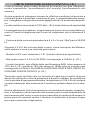
Questo documento si riferisce ai rivelatori: serie GAMMA mod. 654-O e serie GAMMA mod.656C marcati Geca.
La configurazione GAMMA mod. 654-O + GAMMA mod. 656C non è coperta da marchio IMQ.
I rivelatori GAMMA mod. 656C non sono provvisti di marchio IMQ, tuttavia rispettano appieno la normativa CEI UNI EN 50194-
1:2009.
This document refers to gas detectors: GAMMA mod. 654-O and GAMMA mod.656C series marked Geca.
GAMMA mod. 654-O + GAMMA mod. 656C configuration is not IMQ approved.
GAMMA mod. 656C gas detectors have not the IMQ certification, on the other hand they are in accordance with standards
CEI UNI EN 50194.
DESCRIZIONE GENERALE
Il sistema di rilevazione gas è composto dalla centralina serie GAMMA
modello 654-O/M o 654-O/G e dai seguenti rivelatori remoti:
-serie GAMMA mod. 656C/M per gas METANO.
-serie GAMMA mod. 656C/G per gas GPL.
I rivelatori gas modello 654-O/M e 654-O/G sono centraline di gas me-
tano o G.P.L. che avvisano, per mezzo di un segnale ottico ed acustico,
la presenza di gas in ambiente. Essi sono progettati in modo tale da
poter funzionare sia da centralina che da rivelatore remoto.
Modello
Model
GAMMA mod. 654-O/M
GAMMA mod. 654-O/G
GAMMA mod. 656C/M
GAMMA mod. 65C/G
Metano/Methane
GPL/L.P.G
Metano/Methane
GPL/L.P.G
Alimentazione
Power supply
230Vac 50/60Hz /
12Vdc
Gas Rilevato
Gas detected
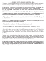
CENTRALINA FUGHE DI GAS PER USO DOMESTICO
GAS CENTRAL UNIT FOR DOMESTIC INSTALLATION
Serie/Series
GAMMA mod. 654-O/M
GAMMA mod. 654-O/G
RIVELATORE FUGHE DI GAS REMOTO
REMOTE GAS LEAK DETECTOR
Serie/Series
GAMMA mod. 656C/M
GAMMA mod. 656C/G
Italiano
English
MadeMade
MadeMade
Made
inin
inin
in
ItalyItaly
ItalyItaly
Italy

I rivelatori gas serie GAMMA mod. 656C/M, mod. 656C/G sono i remoti
da collegare alla centralina serie GAMMA mod. 654-O/M o 654-O/G.
I rivelatori della serie GAMMA sono tarati per rilevare una concentrazio-
ne di gas pari al 10% del L.I.E.(Limite Inferiore di Esplosività), tale so-
glia potrà variare in base alle condizioni ambientali ma non supererà
durante i primi 4 anni di esercizio il 15% del L.I.E. Dopo tale periodo
o in caso di accensione del LED “FAULT” l’apparecchio deve
essere messo fuori servizio o spedito alla casa costruttrice per
una sostituzione completa del dispositivo.
A questo scopo sul coperchio è presente una dicitura sulla quale
deve essere indicata la scadenza del periodo di corretto funziona-
mento (4 anni dalla data di installazione), tale dicitura dovrà essere
compilata dall’installatore del rivelatore al momento dell’installazione.
GENERAL DESCRIPTION
The gas detector system is compound of GAMMA mod. 654-O/M or
GAMMA mod. 654-O/G central unit and the follow remote detectors:
-for Methane: serie GAMMA mod. 656C/M.
-for LPG: serie GAMMA mod. 656C/G .
The detectors GAMMA mod. 654-O/M and GAMMA mod. 654-O/G
are central units of methane and LPG gas, that warns with an optical
and acoustic signal, the presence of gas in the environment
They are planed to be functioning as central unit and as remote unit.
The detectors are calibrated to detect gas up to 10% of the L.E.L.
(Low Explosion Limit), this threshold can change in base of the
environmental conditions but it will not gets over during the first 4
years working, the 15% LEL. After that period or in case of lighting of
the LED “FAULT”, the instrument have to be put out of order or re-send
to manufacturer.
With that aim, the package is provided with a printed label on which
have to be indicated the maturity of correct working period (4 years
from installing date); this printed label have to be filled by who
makes the installation.
SEGNALAZIONI LUMINOSE E ACUSTICHE
Questi rivelatori sono dotati, sulla parete frontale, di tre segnalazioni
luminose.
- LED VERDE (ON): Indica che l'apparecchio è alimentato.
- LED GIALLO (FAULT) : Indica che il sensore gas è guasto.
- LED ROSSO (ALARM): Indica che la concentrazione di gas
misurata nell'aria è superiore alla soglia d'allarme.
!

Nel caso il sensore gas si guasti il rivelatore è in grado di segnalare il
malfunzionamento attivando la suoneria con un intermittenza di due
secondi, accendendo in modo fisso il led giallo e l’uscita relè.
In caso di allarme il rivelatore accende il led rosso e dopo venti secondi
aziona la suoneria ed il relè.
LUMINOUS AND ACOUSTIC SIGNALISATIONS
This gas detectors are provided, on the front panel, by three luminous
signalisations.
In case of damage, the gas detector is able to signals the malfunction,
illuminating in fixed way the yellow led and activating a sound alarm with
two seconds’ of intermittence.
In case of alarm the detector illuminating the red led and after 20
seconds the buzzer emits a sound alarm and the relay activates.
-
GREEN LED (ON): indicates that the instruments is powered.
-YELLOW LED (FAULT): Indicates that the gas sensor is damaged.
- RED LED (ALARM): Indicates that the gas concentration
measured in the air exceeds the alarm threshold.
LIGHTING DELAYS
The catalytic sensor presents in the GAMMA series needs to be heated
for about one minute to working in a correct way and for that reason
when the detector is lighted on the green led will lighten to indicated
that the sensor is in the heating phase. During this time, all the detection
functions will be inhibited.
RITARDO ALL’ACCENSIONE
Il sensore catalitico presente nel rivelatore ha bisogno di essere riscal-
dato per circa un minuto prima di funzionare correttamente, per questo
motivo all’accensione del rivelatore il led verde lampeggerà ad indicare
che il sensore è nella fase di riscaldamento.
Durante tale periodo le funzioni di rivelazione saranno inibite.
INSTALLAZIONE
Attenzione: l’installazione e la messa fuori servizio dell’apparec-
chio devono essere eseguiti da personale tecnico specializzato.
L’installazione di gas e l’eventuale dispositivo di arresto devono essere
conformi alle prescrizioni di legge nazionali vigenti.
INSTALLATION
Attention: the installation and the out of service of the instrument
must be done by skilled personnel only.
The installation of gas and the possible stopping device must be in
according to the national and in force prescriptions law.
!

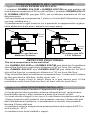
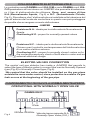
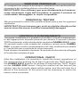
POSIZIONAMENTO DELL’APPARECCHIO
L’apparecchio DEVE ESSERE INSTALLATO:
-I rivelatori GAMMA 654-O/M e GAMMA 656C/M per gas metano ad
una distanza massima di 30 cm dal soffitto; i rivelatori GAMMA 654-O/
G, GAMMA 656C/G per gas G.P.L. ad un’altezza massima di 30 cm
dal pavimento.
-Ad una distanza compresa tra 1 metro e 4 metri dall’utilizzatore a gas
(cucina, caldaia ecc.).
-Possibilmente in ogni locale in cui è presente un apparecchio a gas e,
nelle abitazioni a più piani, almeno uno ogni piano.
DETECTOR POSITIONING
The instrument have to be installed:
-the GAMMA 654-O/M and GAMMA 656C/M gas detector for methane
should be fixed at a maximum distance of 30 cm from the ceiling;
-the GAMMA 654-O/G and GAMMA 656C/G gas detector for LPG
should be fixed at a maximum distance of 30 cm from the floor.
They should be fixed at a distance comprises from 1 meter and 4 meters
by the gas device (kitchen, boiler room, etc…)
Possibly in every room in which there is a gas device and, in the
residences with more that one floor, at least one for each floor.
30cm
max
1-4m
Rivelatore gas Metano
Methane Detector Rivelatore gas GPL
L.P.G. Detector
30cm
max
1-4m
L’apparecchio NON DEVE ESSERE INSTALLATO:
-Direttamente sopra il lavabo o l’apparecchio a gas.
-In locali piccoli dove possano essere utilizzati alcool, ammoniaca,
bombolette spray o altre sostanze a base di solventi volatili.
-In locali chiusi o angoli in cui non c’è una libera circolazione dell’aria.
-Vicino a pareti o altri ostacoli che possano ostruire il flusso del gas
dall’utilizzatore al rivelatore, o ad aspiratori e ventole che possano
deviare il flusso dell’aria.
-In ambienti dove la temperatura possa portarsi al di sopra di 40°C o
al di sotto di -10°C.
-In ambienti con forte umidità o vapori.

Avoid installing:
Directly over the sink or the gas device
In little locals where can be utilised alcohol, ammonia, spray bottles of
gas or other substances with flying solvents.
In low ventilated environments
Near to walls or obstacles that can stop the gas flow from the user to
the detector, or near to exhausters or fans that can divert the air flow
In environment in which the temperature can arrive over 40°C or under –10°C
In environment with a lot of humidity or vapours.
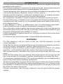
Con l’ausilio di un cacciavite svitare la vite posta sul lato destro dell’ap-
parecchio e sollevare il coperchio. (Fig.1).
Posizionare in modo corretto la base e fissarla sulla scatola ad in-
casso 3 moduli o sulla parete utilizzando viti e tasselli in dotazione.
Per il fissaggio dei tasselli forare la parete con una punta di diametro 5mm.
Fig.1
PROCEDURA PER L’INSTALLAZIONE
INSTALLATION PROCEDURES
By using an screwdriver unscrew on the right hand side the instrument
and uncover it (Fig.1).
Positioning in the correct way the base, on the board mounting 3 modules
boxes directly in the wall by using screws that are provided in the
box. For installing the dowels drilling the wall with a 5mm drill.
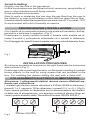
COLLEGAMENTO ELETTRICO: ALIMENTAZIONE
Attenzione: I collegamenti elettrici devono essere effettuati me-
diante cavi sottotraccia.
I rivelatori gas devono essere alimentati a 230Vac-50/60Hz attraverso i
morsetti 1 e 2, oppure a 12Vdc attraverso i morsetti 3 (+) e 4 (-), (Fig.2).
Deve essere previsto un dispositivo per la disconnessione del rivelato-
re dalla rete di alimentazione, con apertura contatti di almeno 3mm se-
condo quanto descritto dalla “Normativa Europea CEI EN 60335-1”.
Fig.2 12Vdc230Vac-50/60Hz
1234
+ +
+ +
+ -

ELECTRICAL CONNECTION: POWER SUPPLY
Attention: the electrical connection has to be done with an under
track cable.
GAMMA gas detector have to be powered at 230Vac 50/60Hz by the
terminals 1 and 2 or with 12Vdc across the clamp 3(+) and 4(-) (Fig. 2).
It has to be provided with an device, to be disowned from the detector
and the feeding net, with minimun 3 mm contact distance in
accordance wit has written in the European Standard EN 60335-1.
CHARACTERISTICS OF THE EXIT-SIGNAL
The central unit it’s provided with an external relay with free tension
contacts, capacity of connection 8A 250Vac / 30Vdc.
CARATTERISTICHE DEL SEGNALE D’USCITA
Le centraline GAMMA 654-O/M e GAMMA 654-O/G sono provviste di
un relè in uscita con i contatti liberi da tensione; portata contatti 8A
250Vac / 30Vdc.
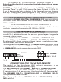
COLLEGAMENTO REMOTO
Le centraline GAMMA 654-O/M e GAMMA 654-O/G possiedono due
moretti (5-6), attivi in chiusura che servono per collegare il seguente
rivelatore remoto (Fig.3):
-per gas METANO: serie GAMMA mod. 656C/M o GAMMA 652-O/M.
-per gas GPL: serie GAMMA mod. 656C/G o GAMMA 652-O/G.
Se ai morsetti 5 e 6 non vengono collegati i remoti, questi devono rima-
nere inalterati, cioè sempre scollegati.
La configurazione GAMMA 654-O + GAMMA 654-O (utilizzato come
remoto) è coperta dal marchio IMQ. La configurazionie GAMMA 654-O
+ GAMMA 656C non è coperta dal marchio IMQ.
serie GAMMA:
mod.
656C / 652-O
CONNECTION FOR VALVE AND REMOTE
The central unit has two clamps (5-6), active in closeness, to be
connected with an remote sensor (Fig.3):
-For METHANE gas: mod.GAMMA 656C/M or GAMMA 652-O/M.
-For LPG gas: mod. GAMMA 656C/G or GAMMA 652-O/G.
If the connectors (5-6) are not used, they have to be left disconnected.
The GAMMA 654-O + (GAMMA 654-O or GAMMA 652-O)
configuration are IMQ certified.
The other configurations, (GAMMA 654-O + GAMMA 656C) is not
IMQ certified.
Fig.3
8
79
34 65
serie GAMMA:
mod.
654-O/M

ELECTRO-VALVES CONNECTION
The central unit gas detector has inside a JUMPER that permits to
select the type of electro-valve to connect that can be Normally Opened
type (Fig.4) or Normally Closed type (Fig.5).
We remind that the valve should be installed on the gas pipes
outside the room under control, since protection is useless if a gas
leak occurs at the beginning of the gas pipe.
Le centraline serie GAMMA mod. 654-O/M e serie GAMMA mod. 654-
O/G possiedono al loro interno un JUMPER che permette di seleziona-
re il tipo di elettrovalvola da utilizzare. Essa puo’ essere di tipo
N.A.(Normalmente Aperta, Fig.4) o N.C. (Normalmente Chiusa,
Fig.5). Ricordiamo che l’elettrovalvola va installata sulla tubazione del
gas all’esterno del locale da controllare in quanto non può proteggere
da perdite che avvengano a monte della stessa.
COLLEGAMENTO ELETTROVALVOLE
Posizione N.A.: ideale per le elettrovalvole Normalmente
Aperte.
Positioning N.O.: proper for normally opened valves
Posizione N.C.: ideale per le elettrovalvole Normalmente
Chiuse o per il controllo contemporaneo dell’elettrovalvola e
di un carico elettrico esterno.
Positioning N.C.: proper for normally closed valves or for
the contemporaneously check of both electro-valve and an
external electrical charge.
JUMPER
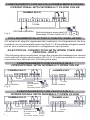
FUNZIONAMENTO CON VALVOLA NORMALMENTE APERTA
230Vac-50/60Hz
Fig.4
OPERATIONAL WITH NORMALLY OPEN VALVE
Valvola riarmo manuale N.A.
Normally Open Valve (N.O.)
GAMMA 654-O
12Vdc

FUNZIONAMENTO CON VALVOLA NORMALMENTE CHIUSA
Fig.5
OPERATIONAL WITH NORMALLY CLOSE VALVE
GAMMA 654-O
230Vac-50/60Hz Valvola riarmo manuale N.C.
Normally Close Valve (N.C.)
12Vdc
Gli schemi di seguito rappresentati mostrano il collegamento tra due
rivelatori con un’unica elettrovalvola (Fig.6-7). E’ possibile collegare anche
più di due rivelatori ripetendo i collegamenti qui riportati.
COLLEGAMENTO ELETTRICO CON PIU’ RIVELATORI:
ELECTRICAL CONNECTION WITH MORE THEN ONE
CENTRAL UNITS:
The following plans mentioned, shows the connection between two central
units with an single electrovalve (Pic.6-7). It’s also possible to connect
more than two central unit, following this plan.
FUNZIONAMENTO CON VALVOLA (N.A.)
OPERATIONAL WITH NORMALLY OPEN VALVE
230Vac-50/60Hz 230Vac-50/60Hz
12Vdc
GAMMA 656C
GAMMA 654-O
Valvola
Normalmente
Aperta
Normally Open Valve
12Vdc
Fig.6
Fig.7
230Vac-50/60Hz 230Vac-50/60Hz
12Vdc
12Vdc
Valvola
Normalmente
Chiusa
Normally Close Valve
GAMMA 654-O GAMMA 656C
FUNZIONAMENTO CON VALVOLA (N.C.)
OPERATIONAL WITH NORMALLY OPEN CLOSE

LIMITE INFERIORE DI ESPLOSIVITA’ (L.I.E.)
L’uso di sistemi diversi dalla bombola di taratura con gas campione,
rende impossibile l’accertamento del corretto funzionamento del
sensore.
Anche quando si volessero ricreare le effettive condizioni di pericolo a
tutela del quale è installato il sensore di gas, è inapplicabile per esem-
pio, l’erogazione di gas dai normali apparecchi di un ambiente domesti-
co.
I nostri rivelatori sono tarati al 10% del L.I.E.(Limite inferiore di esplosività)
La spiegazione è semplice: supponiamo di avere una cucina dalle mi-
sure di 3 metri di larghezza per 4 metri di lunghezza, ed un’altezza di 3
metri.
- Il volume della cucina è equivalente a 4 x 3 x 3 cioè 36m3
pari a 36.000
Lt.
Quando il 4,4% del volume della cucina, viene accupato da Metano,
nella stanza si crea una miscela pericolosa.
- Questo 4,4% vieni chiamato L.I.E. (Limite inferiore di esplosività)
- Nel nostro caso il 4,4% di 36.000Lt corrisponde a 1584Lt.(L.I.E.)
- I nostri rivelatori, per effetto della certificazione IMQ intervengono al
10% del L.I.E., quindi al 10% del valore di 1584Lt che in questo caso
corrisponde a 158,4Lt, QUINDI ALLA DECIMA PARTE DEL LIMITE IN-
FERIORE DI ESPLOSIVITA’ (L.I.E.)
Tenendo conto del fatto che un fornello di casa ha un ugello di pochi
decimi di millimetro e che la pressione è di pochi millibar, se ne deduce
che la portata di gas permetterebbe l’erogazione di 158,4 litri di metano
(quanto basta per fare intervenire il sensore) soltanto dopo ore di tem-
po.
Anche utilizzando fonti di erogazione con portata più ampia, la partico-
lare e fortissima odorizzazione del metano però rende impossibile la
permanenza dell’uomo e comunque trasmette la certezza di essere in
grave pericolo quando anche il metano in ambiente è ancora troppo
poco per consentire l’esplosione.

LOWER EXPLOSIVE LIMIT (L.E.L.)
The use of different systems from the calibration gas sample cylinder,
makes it impossible to verify the proper functioning of the sensor.
Even when you want to recreate the actual conditions of danger for
which protection the gas sensor is installed, this is inapplicable.
As an example, the supply of gas from the normal home kitchen
equipment.
Our detectors are calibrated at 10% LEL (Lower Explosive Limit)
The explanation is simple: lets suppose to have a kitchen measuring 3
meters. wide by 4 meters in length, and with height of 3 meters.
- The volume of the kitchen is equivalent to 4 x 3 x 3 that is 36 m3, equal
to 36,000 Lt.
When 4,4% of the volume of the kitchen, is filled of natural gas, in the
room a dangerous mixture is created.
- This 4,4% is called L.E.L (Lower Explosive Limit)
- In our case a 4,4% of 36.000Lt correspond to 1584Lt. (L.E.L.)
- Our detectors, according to the IMQ approvals operate at 10% of the
LEL, then 10% of the value of 1584Lt, that in this case is 158,4LT,
THEREFORE ONE THENTH OF THE LOWER EXPLOSIVE LIMIT
(L.E.L.)
Taking into consideration the fact that the house cooker has a gas
nozzle of a few tenths of a millimetre and that the gas pressure is of a
few millibars, the gas flow would allow the delivery of 158,4 litres of gas
(sufficient to make the sensor react) only after hours.
Even with broader gas supply sources, the peculiar and strong smell of
natural gas, makes impossible the human presence and it make evident
the serious danger situation even when the natural gas saturation is
still too little to allow the explosion.

VERIFICHE PERIODICHE
Si consiglia di far eseguire dal proprio installatore una verifica del fun-
zionamento del rivelatore almeno una volta l’anno.
IMPORTANTE: Non utilizzare gas puro direttamente sul sensore,
come ad esempio il gas dell’accendino, in quanto il sensore ne
risulterebbe danneggiato in modo irreparabile.
PERIODICAL TESTING
We recommend to contact the installer at least once a year for a general
verification
IMPORTANT: Do not use pure gas, such as a lighter, directly on the
sensor since the sensor could be irremediably damaged.
CONTROLLO FUNZIONAMENTO
Terminata l’installazione è possibile controllare il corretto funzionamen-
to dell’apparecchio tenendo premuto per almeno 2 secondi il tastino
TESTposizionato sulla scheda della centralina GAMMA 654-O, o per
30 secondi quello sulla scheda del rivelatore remoto serie GAMMA
656C, in questo modo si accenderanno tutti i led, si attiverà la suoneria
e l’uscita relè per un periodo di cinque secondi.
Sarà dunque necessario riarmare l’eventuale elettrovalvola collegata
all’uscita del rivelatore di gas.
OPERATIONAL CHECK
After the installation it is possible to check the correct operational of
the instrument by pushing for at least 2 seconds the TEST button on
the GAMMA 654-O board or for at least 30 seconds the “TEST” button
on the GAMMA 656C board. Using this method all the leds will be
lighted, also the acoustic alarm will be active, and the exit relay for a
period of five seconds. At this point it will be necessary to rearm the
electro valve connected.

AVVERTENZE
Per la pulizia dell’apparecchio utilizzare un panno per togliere la polvere
posatasi sull’involucro.
Non tentare di aprire o smontare il rivelatore di gas, tale operazione può
causare scossa elettrica oltre a danneggiare il prodotto.
Tenere presente che il sensore ha una buona resistenza a prodotti d’uso
comune quali spray, detersivi, alcool, colle o vernici.
Questi prodotti possono contenere sostanze che, in qualità elevate,
interferiscono con il sensore provocando falsi allarmi.
Si consiglia di ventilare il locale quando si utilizzano questi prodotti.
Si rammenta che il rivelatore non è in grado di rilevare perdite che av-
vengano fuori dal locale in cui è installato oppure all’interno dei muri o
sotto al pavimento.
Il gas (Metano o GPL), è addizionato con un odorizzante particolar-
mente fastidioso per renderlo identificabile mediante l’olfatto.
Se un fornello rimane aperto anche per parecchi minuti non genera la
quantità di gas fuoriuscito tale da provocare l’allarme del rivelatore (pur
essendo chiaramente percettibile a “naso”).
Infatti la quantità di gas presente nel locale può essere al di sotto della
soglia d’allarme.
Il rivelatore non può funzionare in assenza di alimentazione.
WARNING
For the cleaning, use an cloth on the top. Not be opened, it could
cause damage.
Note that the sensor employed has a good resistance towards products
such as sprays, detergents, alcohol, glues and paints.
However, these products could contain substances which, if in great
quantity, could interfere with the sensor and cause false alarms.
We recommend to ventilate the room should products like these be
used.
Note that the detector is not able to detect gas leaks occurring outside
the room where it is installed, neither inside walls nor under the floor.
To make gas (methane and LPG) nose identifiable, gas is added with a
particularly disturbing smelling substance.
Small gas quantities coming out from left open cookers for some minutes
do not cause the gas detector alarm signalling even if it is clearly nose
perceptible; in fact the quantity of gas presents in the environment can
be under the alarm threshold.
Please remember that the gas detector cannot work without power
supply.

WARNING!! In case of alarm:
1) Extinguish all naked flames.
2) Turn off the gas supply at the gas emergency control and/or, with
a LPG supply, the storage tank.
3) Do not switch on or off any electrical lights. Do not activate any
electrically powered devices.
4) Open both doors and windows to increase room ventilation.
If the alarm stops, it is necessary to identify the alarm reason and
act accordingly.
If the alarm condition continues and the cause of the leak is not
apparent and/or cannot be corrected, vacate the premises and
immediately notify the gas emergency service.
ATTENZIONE! In caso d'allarme:
1) Spegnere tutte le fiamme libere.
2) Chiudere il rubinetto del contatore del gas o della bombola GPL.
3) Non accendere o spegnere luci; non azionare apparecchi o
dispositivi alimentati elettricamente.
4) Aprire porte e finestre per aumentare la ventilazione dell'ambiente.
Se l'allarme cessa è necessario individuare la causa che l'ha
provocato e provvedere di conseguenza.
Se l'allarme continua e la causa di presenza gas non è individuabile
o eliminabile abbandonare l'immobile e, dall'esterno, avvisare il
servizio d'emergenza.
DA COMPILARSI A CURA DELL’INSTALLATORE:
Data di installazione ____________________________________
Data sostituzione rivelatore_______________________________
Locale di installazione ___________________________________
Numero di serie apparecchio ______________________________
(Da leggere sulla parte interna dell’involucro in plastica)
Timbro
Firma ______________________________________________

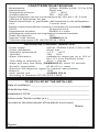
TECHNICAL CHARACTERISTICS
- Power supply: 230Vac, 50/60Hz 4,6VA / 12Vcc 2,5W
- Power dissiaption: 20mA max
- Operation temperature: -10°C…. +40°C
- Humidity: 30%…. 90%
- Alarm intervention calibrated to detect gas up to 10% of
the L.E.L.(Low Explosion Limit).
- Time delay at switching on about 1 minutes
- Alarm and relay time delay (GAMMA654-O): about 20 seconds
- Acoustic signalisation: 85 dB (A) in 1 meter
- Electrical self-diagnosis signal for eventual abnormalities
- Rated to: IP42
- Input remote unit: (GAMMA 654-O)
- According to Standard CEI EN 5029-1:2009
CARATTERISTICHE TECNICHE
- Alimentazione: 230Vac, 50/60Hz 4,6VA / 12 Vcc 2,5W
- Assorbimento: 20mA max
- Temperatura di lavoro: -10°C ... +40°C
- Umidità relativa: 30% ... 90% UR
- Soglia d'intervento ad una concentrazione del 10% del L.I.E. (Limite
Inferiore di Esplosività) del gas.
- Ritardo intenzionale di preriscaldo dall'inserzione in rete dell'apparec-
chio: 1 minuto circa
- Ritardo intenzionale allarme acustico e comando relè centralina GAMMA
654-O : 20 secondi circa.
- Segnalazione acustica: 85dB(A) a 1 metro
- Autodiagnosi elettronica con segnalatore eventuali anomalie
- Grado di protezione: IP42
- Ingresso unità remota: (GAMMA 654-O)
- Conforme alla norma CEI UNI EN 50194-1:2009
TO BE FILLED BY THE INSTALLER:
Date of installation _____________________________________
Substitution date_______________________________________
Installation LOCAL _____________________________________
Instruments’ Serial number (s.n.) __________________________
(to read on the internal part of the plastic involucres)
Stamp
Signed ________________________________________

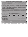
CERTIFICATO DI GARANZIA
DA COMPILARE E SPEDIRE IN CASO DI GUASTO
APPARECCHIO: 654-O/M 654-O/G 656C/M 656C/G
Numero di serie (s.n.)___________________________________
RIVENDITORE
Timbro: Data di acquisto:
_____/_____/_____
UTILIZZATORE
Cognome e nome _______________________________________
Via_______________________________________n°___________
C.A.P.______________Città________________________________
Telefono________________________________________________
CONDIZIONI GENERALI DI GARANZIA
IL PRESENTE CERTIFICATO E' L' UNICO DOCUMENTO CHE DA'
DIRITTO ALLA RIPARAZIONE DEL PRODOTTO IN GARANZIA
- Il prodotto é GARANTITO per un periodo di 24 mesi dalla data di
acquisto.
- Non sono coperti da GARANZIA eventuali danni derivati da
manomissioni, uso ed installazione errati o impropri.
- La GARANZIA è valida solo se debitamente compilata.
- In caso di difetti coperti da GARANZIA, il produttore riparerà o
sostituirà il prodotto gratuitamente.
PRESTAZIONI FUORI GARANZIA:
Trascorsi i termini o la durata della GARANZIA le eventuali riparazioni
verranno addebitate in funzione alle parti sostituite e al costo della
manodopera.

GENERAL GUARANTEE CONDITIONS
THIS CERTIFICATE IS THE ONLY DOCUMENT THAT GIVES THE
RIGHT FOR THE REPAIR OF THE PRODUCT UNDER
GUARANTEE.
- The product is GUARANTEED for a period of 24 months from the
purchase date.
- Damage caused by tampering, incorrect or improper use and
installation is not covered by the GUARANTEE.
- The GUARANTEE is valid only if it is duly compiled.
- In the event of defects covered by the GUARANTEE, the
manufacturer will repair or substitute the product free of charge.
SERVICING AFTER THE GUARANTEE PERIOD
Any repairs after the period of the GUARANTEE will be charged on
the basis of the parts substituted and the labour costs.
WARRANTY CERTIFICATE
TO COMPILE AND SEND IN CASE OF DAMAGE
DEVICE: 654-O/M 654-O/G 656C/M 656C/G
Serial number(s.n.)______________________________________
DEALER
Stamp: Date of purchase:
_____/_____/_____
USER
Surname and name______________________________________
Address _________________________________n°___________
City __________________________________________________
Telephone___________________________________________________
La ditta costruttrice si riserva il diritto di apportare qualsiasi modifica, estetica o
funzionale, senza preavviso alcuno ed in qualsiasi momento.
The manufacturer firm reserves the right to make any aesthetic or functional
modificationswithout notice and at any moment.
GECA Srl
via E.Fermi, n°98
25064 Gussago (BS) Italy
Tel. +39 030 3730218
www.gecasrl.it
Tecnocontrol Srl
via Miglioli, n°47
20090 Segrate (MI) Italy
Tel. +39 02 26922890
www.tecnocontrol.it
Dis.0134179 PROV Cod.2.710.1509 Made in ItalyMade in Italy
Made in ItalyMade in Italy
Made in Italy
-
 1
1
-
 2
2
-
 3
3
-
 4
4
-
 5
5
-
 6
6
-
 7
7
-
 8
8
-
 9
9
-
 10
10
-
 11
11
-
 12
12
-
 13
13
-
 14
14
-
 15
15
-
 16
16


EPH Controls Gamma654LPG Instruções de operação
- Categoria
- Brinquedos
- Tipo
- Instruções de operação
- Este manual também é adequado para
em outras línguas
Artigos relacionados


Outros documentos
-
BALTUR BTG 15 P 50-60Hz Use and Maintenance Manual
-
Risco iWISE QUAD AM Grade 3 Manual do usuário
-
-
Chacon 34148 Manual do usuário
-
 RISCO Group WatchOUT Guia de instalação
-
-
Risco Industrial LuNAR RK200DTG3 Guia de instalação
-
Chacon 34151 Manual do usuário
