Risco Industrial LuNAR RK200DTG3 Guia de instalação
- Categoria
- Detectores de movimento
- Tipo
- Guia de instalação

D
D
D
T
T
A
A
A
M
M
G
G
G
r
r
r
a
a
a
d
d
d
e
e
3
3
H
i
g
h
C
e
i
l
i
n
g
M
o
u
n
t
D
e
t
e
c
t
o
r
r
I
n
s
t
a
l
l
a
t
i
o
n
G
u
i
d
e
M
o
d
e
l
:
R
R
K
K
2
0
0
D
T
G
3

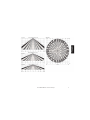
DT AM Grade 3
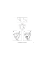
Model: RK200DTG3
High Ceiling Mount Detector Installation Guide
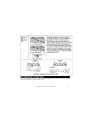
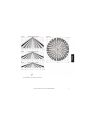
General Description
The Industrial LuNAR DT AM Grade 3 (RK200DTG3) is a dual technology ceiling detector with a mounting height of
up to 8.6m (28ft) that incorporates RISCO Group’s Anti-Cloak™ Technology (ACT™). The detector has an Intelligent
Digital Signal Processing method that automatically adjusts the alarm threshold and pulse count verification
according to actual intruder crossing speed and environmental factors, providing superior detection and false
alarm immunity.
The Ind. LuNAR RK200DTG3 can operate as a regular relay detector connected to any control panel, or as an
addressable BUS detector when connected to RISCO Group’s ProSYS control panel via the RS485 BUS.

2 Ind. LuNAR RK200DTG3 Installation Guide
Ind. LuNAR RK200DTG3 Features
♦
PD6662, EN50131-1, EN50131-2-4 Grade 3
♦
Addressable Dual Technology detector with Anti-Cloak™ Technology
♦
Up to 8.6 m (28ft) mounting height
♦
360
0
by 18m (60ft) diameter coverage pattern
♦
3 independent PIR channels for customized coverage
♦
Intelligent Digital Signal Processing – alarm verification and decision thresholds adjusted according to
actual intruder crossing speed
♦
Built-in Triple EOL resistors, jumper selectable
♦
Active IR for Anti-Masking meeting EN50131 requirements
♦
Ceiling and cover tampers
♦
"Green Line" setting – for disabling the MW when the premises are occupied
♦
Opto–relays for low current consumption and long life
♦
Remote and Local Self Test
♦
Remote SET input
♦
Remote RC control input
♦
PIR coverage optimization by sliding the lenses
♦
Microwave Range Adjustment manually (analog trimmer) and remotely (digital setting)
♦
Trouble Indication (by LEDs or via communication)
♦
3 Triple color LEDs for easy walk testing
♦
Advanced Remote control and diagnostics
♦
Reduced Power Consumption when connected to RISCO Group’s ProSYS

Ind. LuNAR RK200DTG3 Installation Guide 3
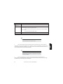
Remote Control and Diagnostic Features
*
*Via the optional Bi-Directional Infrared Remote Control, or the ProSYS Upload/Download Software and
Keypad.
Detection Method
The Ind. LuNAR RK200DTG3 detection is based on:
♦ PIR (Passive Infra-Red) - which responds to changes in the IR radiation caused when an intruder crosses
the protected area.
♦ MW (Microwave) - which transmits signals and analyzes the frequency changes of the reflected echo
from an intruder using Doppler Effect.
ALARM is initiated only when both technologies trigger simultaneously (except for certain situations in the ACT
mode-see page 4 – “How ACT™ Works”), thus greatly reducing the possibility of false alarms.
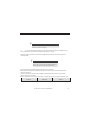
How ACT™ Works
Anti-Cloak™ Technology (ACT™) provides the benefits of DT (Dual Technology) while avoiding its
drawbacks. This patent pending innovation has created a new standard for detectors. Dual Technology, a
combination of PIR +MW, was an important development for the security industry...but, it has 2 major
weaknesses:
IR emission blocking cloaks employed by intruders enable avoidance of detection.
PIR sensitivity is reduced when the protected area’s ambient temperature approaches body temperature.
Responding to requests from its customer base to solve these pressing problems, RISCO Group developed
ACT™ -a revolutionary anti-cloak solution.
♦
Remote microwave adjustment enables one-man walk test.
♦
Diagnostic tools include detector input voltage reading and status of each PIR channel and MW
channel (signal voltage and noise levels), AM channel (signal voltage), SW version verification.
♦
Remote display and control of detector settings: MW adjustment, ACT on/off, LEDs on/off.
♦
Remote trouble indication (Pass/Fail) for the PIR, MW and power supply input
♦
Control of MW bypass (during MW trouble) and MW disable during Disarm ("Green Line") when
connected to ProSYS.

4 Ind. LuNAR RK200DTG3 Installation Guide
ACT™ prevents the alarm system from being bypassed, by neutralizing attempts to camouflage IR radiation.
Using unique pattern recognition algorithms, ACT™ distinguishes between the weak IR signal of a moving
intruder and the background noise and thermal interferences that may cause false alarms.
Once the presence of an intruder is recognized, ACT™ switches the system automatically from dual channel
PIR/MW mode to single channel MW mode for a predetermined period of time, in order to trigger an alarm
utilizing the MW channel, and then returns to dual channel mode.
In the second case, when the ambient temperature approaches body temperature, the ACT™ switches to
microwave-only detection.
Offering significantly higher detection capabilities as well as immunity from false alarms, ACT™ thwarts even
the most sophisticated burglars.
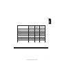
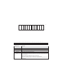
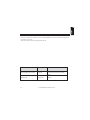
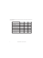
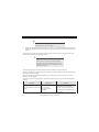
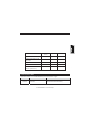
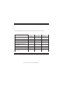
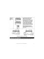
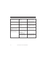
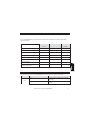
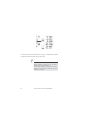
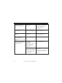
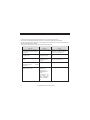
Ind. LuNAR RK200DTG3 Configuration Options
The Ind. LuNAR RK200DTG3 can be configured and/or diagnosed remotely via one of the options:

Ind. LuNAR RK200DTG3 Installation Guide 5
Manual
configuration
Remote
Control
Device
ProSYS Bus
Control
ACT Mode
LEDs
MW Sensitivity
(by trimmer)
Diagnostics
-
Status/Trouble/Info Reports
-
AM Diagnostics
-
-
MW Bypass
-
-
MW Disable on Disarm ("Green
Line")
-
-
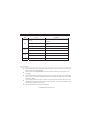
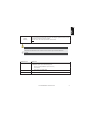
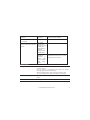
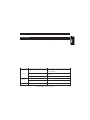
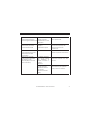
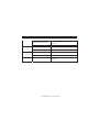
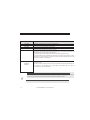
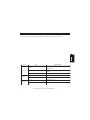
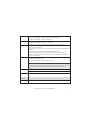
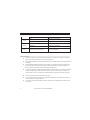
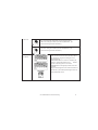
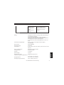
LED Display
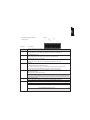
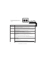
The three Tri color LEDs in the Ind. LuNAR RK200DTG3, operate as herein described:

6 Ind. LuNAR RK200DTG3 Installation Guide
LED
STATE
MEANING
Red
Steady
Detector alarm (simultaneous PIR and MW
detection)
Flashing with low frequency
Indicates malfunctioned communication with
ProSYS
Flashing with high frequency
AM detection
Green
Steady
Microwave detection
Flashing
Trouble in the MW channel
Orange
Steady
PIR detection
Flashing
Trouble in the PIR channel
All LEDs
Flashing with change of color
Upon power up
INSTALLATION
Preliminary steps:
♦
Before installation, study the space to be protected carefully in order to choose the exact location of
the unit for the best possible coverage.
♦
Never install the Ind. LuNAR RK200DTG3 in an environment that causes an alarm condition in one
technology.
♦
Avoid installations where rotating machines (e.g. fans) are normally in operation within the coverage
pattern. Point the unit away from glass exposed to the outdoors and objects that may change
temperature rapidly.
♦
Do not mount the detector in direct sunlight or near any heat sources. Detection sectors should be
pointed either towards a wall, floor but not towards windows or curtains. The installation surface
should be solid, smooth and vibration free
♦
Eliminate interference from nearby outside sources.

Ind. LuNAR RK200DTG3 Installation Guide 7
♦
For optimum detection, select a location likely to intercept an intruder moving across the coverage
pattern.
♦
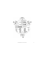
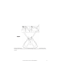
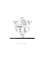
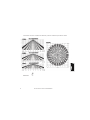
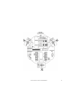
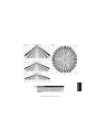
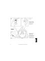
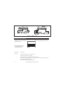
Recommended mounting heights that allow 18m (60ft) detection, are from 3.7m to 8.6m.
♦
The detector must be mounted on the ceiling, preferably in the center of the room.
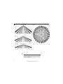
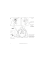
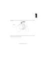
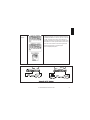
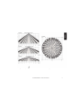
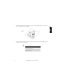
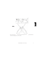
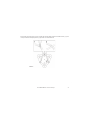
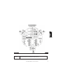
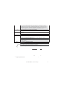
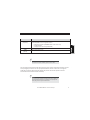
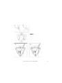
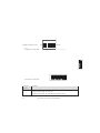
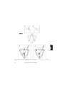
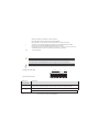
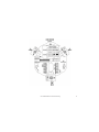
Typical Ind. LuNAR RK200DTG3 detection coverage and installation height, are illustrated below:

8 Ind. LuNAR RK200DTG3 Installation Guide
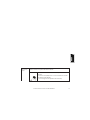
NOTE:
When installing the Ind. LuNAR RK200DTG3 detector in a
room occupied with high volume interfering elements, MW
detection may be affected.

Ind. LuNAR RK200DTG3 Installation Guide 9

10 Ind. LuNAR RK200DTG3 Installation Guide
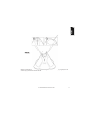
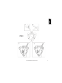
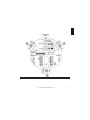
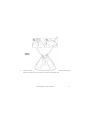
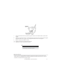
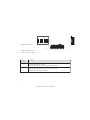
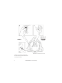
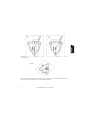
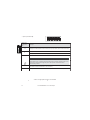
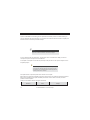
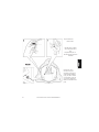
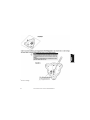
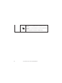
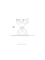
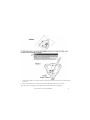
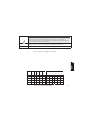
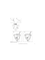
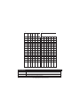
Installation Process:
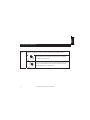
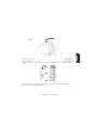
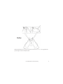
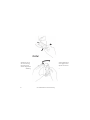
To open the detector (Figure 1), remove the cover by inserting a screwdriver (1) in the recess between the
detector’s protection cap and the cover. The cover will remain attached to the base of the detector.
Using a Philips screwdriver, release the upper cover screw (2) and gently pull upward the detector’s upper
cover.

Ind. LuNAR RK200DTG3 Installation Guide 11
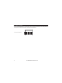
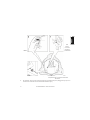
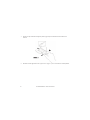
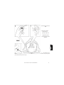
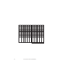
Release the PCB holding screw (Figure 2) located on the right hand side of the PCB (1), pull gently the two
release clips (2) outward and remove the PCB.
(1
1
1
2
2

12 Ind. LuNAR RK200DTG3 Installation Guide
Do not touch the PIR
sensors!
Do not remove
the white filters from
their
position! They are
essential for
correct operation
of the detector.
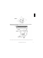
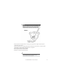
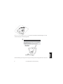
If required, open (Figure
3) the wiring channels
knockout using a cutter
(1, 2) and knockout holes
in the rear cover (3, 4)
using a screwdriver.

Ind. LuNAR RK200DTG3 Installation Guide 13

14 Ind. LuNAR RK200DTG3 Installation Guide
Insert the cable via the cable opening (Figure 4) and connect the desired wires as described in “Step 4-
Wiring”.

Ind. LuNAR RK200DTG3 Installation Guide 15
Return the PCB to its previous location and verify that it is well secured by the holding clips and the screw.

16 Ind. LuNAR RK200DTG3 Installation Guide
Perform lens adjustment and DIP switch settings as described in “Lens Adjustment” on page 12 and on page
15.
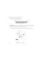
Mount the top cover on the detector’s base.
Tighten the top cover’s central screw.
Replace the detector’s protection cap.
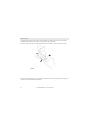
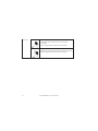
NOTE:
For a ceiling tamper, affix the back tamper screw as
shown in Figure 5.
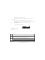
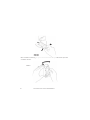
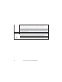
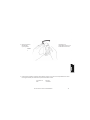
Lens Adjustment:
The Ind. LuNAR RK200DTG3 has three - Fresnel lenses attached to the cover, located in sensor protective
sleeves. Adjust the position of the lenses based on the ceiling mounting height as follows:
Press the 2 clips attaching the sleeve (Figure 6) to the detector’s cover, and gently pull out the sleeve.
FIGURE 6

Ind. LuNAR RK200DTG3 Installation Guide 17
Remove the lens from the sleeve (Figure 7) by gently lifting it from the holding pins that secure it to the sides
of the sleeve.
FIGURE 7
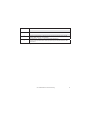
Place the two pins, which are located on both sides of the sleeve into the matching slots on the lens. Use the
following table to select the desired lens position.

18 Ind. LuNAR RK200DTG3 Installation Guide
Return the protective sleeve back into place on the detector front cover.
Repeat steps 1 to 5 for the remaining 2 lenses.
NOTES:
Below 3.7m mounting height, the coverage diameter starts
decreasing, and at 2.7m height coverage diameter is 15m (50ft). For
customized coverage, it is possible to set the position of each lens to a
different height, according to the installation conditions.

Ind. LuNAR RK200DTG3 Installation Guide 19
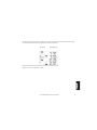
Selectors and Jumpers
A página está carregando...
A página está carregando...
A página está carregando...
A página está carregando...
A página está carregando...
A página está carregando...
A página está carregando...
A página está carregando...
A página está carregando...
A página está carregando...
A página está carregando...
A página está carregando...
A página está carregando...
A página está carregando...
A página está carregando...
A página está carregando...
A página está carregando...
A página está carregando...
A página está carregando...
A página está carregando...
A página está carregando...
A página está carregando...
A página está carregando...
A página está carregando...
A página está carregando...
A página está carregando...
A página está carregando...
A página está carregando...
A página está carregando...
A página está carregando...
A página está carregando...
A página está carregando...
A página está carregando...
A página está carregando...
A página está carregando...
A página está carregando...
A página está carregando...
A página está carregando...
A página está carregando...
A página está carregando...
A página está carregando...
A página está carregando...
A página está carregando...
A página está carregando...
A página está carregando...
A página está carregando...
A página está carregando...
A página está carregando...
A página está carregando...
A página está carregando...
A página está carregando...
A página está carregando...
A página está carregando...
A página está carregando...
A página está carregando...
A página está carregando...
A página está carregando...
A página está carregando...
A página está carregando...
A página está carregando...
A página está carregando...
A página está carregando...
A página está carregando...
A página está carregando...
A página está carregando...
A página está carregando...
A página está carregando...
A página está carregando...
A página está carregando...
A página está carregando...
A página está carregando...
A página está carregando...
A página está carregando...
A página está carregando...
A página está carregando...
A página está carregando...
A página está carregando...
A página está carregando...
A página está carregando...
A página está carregando...
A página está carregando...
A página está carregando...
A página está carregando...
A página está carregando...
A página está carregando...
A página está carregando...
A página está carregando...
A página está carregando...
A página está carregando...
A página está carregando...
A página está carregando...
A página está carregando...
A página está carregando...
A página está carregando...
A página está carregando...
A página está carregando...
A página está carregando...
A página está carregando...
A página está carregando...
A página está carregando...
A página está carregando...
A página está carregando...
A página está carregando...
A página está carregando...
A página está carregando...
A página está carregando...
A página está carregando...
A página está carregando...
A página está carregando...
A página está carregando...
A página está carregando...
A página está carregando...
A página está carregando...
A página está carregando...
A página está carregando...
A página está carregando...
A página está carregando...
A página está carregando...
A página está carregando...
A página está carregando...
A página está carregando...
A página está carregando...
A página está carregando...
A página está carregando...
A página está carregando...
A página está carregando...
A página está carregando...
A página está carregando...
A página está carregando...
A página está carregando...
A página está carregando...
A página está carregando...
A página está carregando...
A página está carregando...
A página está carregando...
A página está carregando...
A página está carregando...
A página está carregando...
A página está carregando...
A página está carregando...
A página está carregando...
A página está carregando...
A página está carregando...
A página está carregando...
A página está carregando...
A página está carregando...
A página está carregando...
A página está carregando...
A página está carregando...
A página está carregando...
A página está carregando...
A página está carregando...
A página está carregando...
A página está carregando...
A página está carregando...
A página está carregando...
A página está carregando...
A página está carregando...
A página está carregando...
A página está carregando...
A página está carregando...
A página está carregando...
A página está carregando...
A página está carregando...
A página está carregando...
A página está carregando...
A página está carregando...
A página está carregando...
A página está carregando...
A página está carregando...
A página está carregando...
A página está carregando...
A página está carregando...
A página está carregando...
A página está carregando...
A página está carregando...
A página está carregando...
A página está carregando...
A página está carregando...
A página está carregando...
A página está carregando...
A página está carregando...
A página está carregando...
A página está carregando...
A página está carregando...
A página está carregando...
A página está carregando...
A página está carregando...
A página está carregando...
A página está carregando...
-
 1
1
-
 2
2
-
 3
3
-
 4
4
-
 5
5
-
 6
6
-
 7
7
-
 8
8
-
 9
9
-
 10
10
-
 11
11
-
 12
12
-
 13
13
-
 14
14
-
 15
15
-
 16
16
-
 17
17
-
 18
18
-
 19
19
-
 20
20
-
 21
21
-
 22
22
-
 23
23
-
 24
24
-
 25
25
-
 26
26
-
 27
27
-
 28
28
-
 29
29
-
 30
30
-
 31
31
-
 32
32
-
 33
33
-
 34
34
-
 35
35
-
 36
36
-
 37
37
-
 38
38
-
 39
39
-
 40
40
-
 41
41
-
 42
42
-
 43
43
-
 44
44
-
 45
45
-
 46
46
-
 47
47
-
 48
48
-
 49
49
-
 50
50
-
 51
51
-
 52
52
-
 53
53
-
 54
54
-
 55
55
-
 56
56
-
 57
57
-
 58
58
-
 59
59
-
 60
60
-
 61
61
-
 62
62
-
 63
63
-
 64
64
-
 65
65
-
 66
66
-
 67
67
-
 68
68
-
 69
69
-
 70
70
-
 71
71
-
 72
72
-
 73
73
-
 74
74
-
 75
75
-
 76
76
-
 77
77
-
 78
78
-
 79
79
-
 80
80
-
 81
81
-
 82
82
-
 83
83
-
 84
84
-
 85
85
-
 86
86
-
 87
87
-
 88
88
-
 89
89
-
 90
90
-
 91
91
-
 92
92
-
 93
93
-
 94
94
-
 95
95
-
 96
96
-
 97
97
-
 98
98
-
 99
99
-
 100
100
-
 101
101
-
 102
102
-
 103
103
-
 104
104
-
 105
105
-
 106
106
-
 107
107
-
 108
108
-
 109
109
-
 110
110
-
 111
111
-
 112
112
-
 113
113
-
 114
114
-
 115
115
-
 116
116
-
 117
117
-
 118
118
-
 119
119
-
 120
120
-
 121
121
-
 122
122
-
 123
123
-
 124
124
-
 125
125
-
 126
126
-
 127
127
-
 128
128
-
 129
129
-
 130
130
-
 131
131
-
 132
132
-
 133
133
-
 134
134
-
 135
135
-
 136
136
-
 137
137
-
 138
138
-
 139
139
-
 140
140
-
 141
141
-
 142
142
-
 143
143
-
 144
144
-
 145
145
-
 146
146
-
 147
147
-
 148
148
-
 149
149
-
 150
150
-
 151
151
-
 152
152
-
 153
153
-
 154
154
-
 155
155
-
 156
156
-
 157
157
-
 158
158
-
 159
159
-
 160
160
-
 161
161
-
 162
162
-
 163
163
-
 164
164
-
 165
165
-
 166
166
-
 167
167
-
 168
168
-
 169
169
-
 170
170
-
 171
171
-
 172
172
-
 173
173
-
 174
174
-
 175
175
-
 176
176
-
 177
177
-
 178
178
-
 179
179
-
 180
180
-
 181
181
-
 182
182
-
 183
183
-
 184
184
-
 185
185
-
 186
186
-
 187
187
-
 188
188
-
 189
189
-
 190
190
-
 191
191
-
 192
192
-
 193
193
-
 194
194
-
 195
195
-
 196
196
-
 197
197
-
 198
198
-
 199
199
-
 200
200
-
 201
201
-
 202
202
-
 203
203
-
 204
204
-
 205
205
-
 206
206
-
 207
207
-
 208
208
-
 209
209
-
 210
210


Risco Industrial LuNAR RK200DTG3 Guia de instalação
- Categoria
- Detectores de movimento
- Tipo
- Guia de instalação
em outras línguas
- español: Risco Industrial LuNAR RK200DTG3 Guía de instalación
- français: Risco Industrial LuNAR RK200DTG3 Guide d'installation
- italiano: Risco Industrial LuNAR RK200DTG3 Guida d'installazione
- English: Risco Industrial LuNAR RK200DTG3 Installation guide
- Nederlands: Risco Industrial LuNAR RK200DTG3 Installatie gids
Artigos relacionados
-
Risco WL T312 Installation Instructions Manual
-
 RISCO Group WatchOUT Guia de instalação
-
-
-
-
-
-
-
Risco RWX34S Installation Instructions Manual
-

Outros documentos
-
Minelab Minelab F3Ci Countermine Detector Guia de usuario
-
CAME SDT325 Guia de instalação
-
-
 Elkron IRA 14 Guia de instalação
-
DSC LC-181 Manual do usuário
-
 Elkron IRA 15P Guia de instalação
-
-
-
CAME PROXINET Guia de instalação
-

