A página está carregando...

D
D
T
T
A
A
M
M
G
G
r
r
a
a
d
d
e
e
3
3
H
H
i
i
g
g
h
h
C
C
e
e
i
i
l
l
i
i
n
n
g
g
M
M
o
o
u
u
n
n
t
t
D
D
e
e
t
t
e
e
c
c
t
t
o
o
r
r
I
I
n
n
s
s
t
t
a
a
l
l
l
l
a
a
t
t
i
i
o
o
n
n
G
G
u
u
i
i
d
d
e
e
English Italiano
Português
Françias Español
Nederlands


D
D
T
T
A
A
M
M
G
G
r
r
a
a
d
d
e
e
3
3
M
M
o
o
d
d
e
e
l
l
:
:
I
I
n
n
d
d
.
.
L
L
u
u
N
N
A
A
R
R
2
2
0
0
0
0
D
D
T
T
G
G
3
3
H
H
i
i
g
g
h
h
C
C
e
e
i
i
l
l
i
i
n
n
g
g
M
M
o
o
u
u
n
n
t
t
D
D
e
e
t
t
e
e
c
c
t
t
o
o
r
r
I
I
n
n
s
s
t
t
a
a
l
l
l
l
a
a
t
t
i
i
o
o
n
n
G
G
u
u
i
i
d
d
e
e
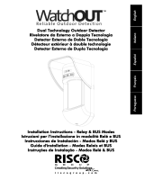
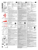
English

Ind. LuNAR 200DTG3 Installation Guide 2
General Description
The Industrial LuNAR DT AM Grade 3 (Ind. LuNAR 200DTG3) is a dual technology ceiling detector with
a mounting height of up to 8.6m (28ft) that incorporates RISCO Group’s Anti-Cloak™ Technology
(ACT™). The detector has an Intelligent Digital Signal Processing method that automatically adjusts the
alarm threshold and pulse count verification according to actual intruder crossing speed and
environmental factors, providing superior detection and false alarm immunity.
The Ind. LuNAR 200DTG3 can operate as a regular relay detector connected to any control panel, or as
an addressable BUS detector when connected to RISCO Group’s ProSYS control panel via the RS485
BUS.
Ind. LuNAR 200DTG3 Features
♦ PD6662, EN50131-1, TS50131-2-4 Grade 3
♦ Addressable Dual Technology detector with Anti-Cloak™ Technology
♦ Up to 8.6 m (28ft) mounting height
♦ 360
0
by 18m (60ft) diameter coverage pattern
♦ 3 independent PIR channels for customized coverage
♦ Intelligent Digital Signal Processing – alarm verification and decision thresholds adjusted
according to actual intruder crossing speed
♦ Built-in Triple EOL resistors, jumper selectable
♦ Active IR for Anti-Masking meeting TS50131 requirements
♦ Ceiling and cover tampers
♦ "Green Line" setting – for disabling the MW when the premises are occupied
♦ Opto–relays for low current consumption and long life
♦ Remote and Local Self Test
♦ Remote SET input
♦ Remote RC control input
♦ PIR coverage optimization by sliding the lenses
♦ Microwave Range Adjustment manually (analog trimmer) and remotely (digital setting)
♦ Trouble Indication (by LEDs or via communication)
♦ 3 Triple color LEDs for easy walk testing
♦ Advanced Remote control and diagnostics
♦ Reduced Power Consumption when connected to RISCO Group’s ProSYS

Ind. LuNAR 200DTG3 Installation
Guide 3
Remote Control and Diagnostic Features*
♦ Remote microwave adjustment enables one-man walk test.
♦ Diagnostic tools include detector input voltage reading and status of each PIR channel and
MW channel (signal voltage and noise levels), AM channel (signal voltage), SW version
verification.
♦ Remote display and control of detector settings: MW adjustment, ACT on/off, LEDs on/off.
♦ Remote trouble indication (Pass/Fail) for the PIR, MW and power supply input
♦ Control of MW bypass (during MW trouble) and MW disable during Disarm ("Green Line")
when connected to ProSYS.
*Via the optional Bi-Directional Infrared Remote Control, or the ProSYS Upload/Download
Software and Keypad.
Detection Method
The Ind. LuNAR 200DTG3 detection is based on:
♦ PIR (Passive Infra-Red) - which responds to changes in the IR radiation caused when an
intruder crosses the protected area.
♦ MW (Microwave) - which transmits signals and analyzes the frequency changes of the
reflected echo from an intruder using Doppler Effect.
ALARM is initiated only when both technologies trigger simultaneously (except for certain situations in
the ACT mode-see page 4 – “How ACT™ Works”), thus greatly reducing the possibility of false alarms.
English

Ind. LuNAR 200DTG3 Installation Guide
4
How ACT™ Works
Anti-Cloak™ Technology (ACT™) provides the benefits of DT (Dual Technology) while avoiding its
drawbacks. This patent pending innovation has created a new standard for detectors.
Dual Technology, a combination of PIR +MW, was an important development for the security
industry...but, it has 2 major weaknesses:
IR emission blocking cloaks employed by intruders enable avoidance of detection.
PIR sensitivity is reduced when the protected area’s ambient temperature approaches body
temperature.
Responding to requests from its customer base to solve these pressing problems, RISCO Group
developed ACT™ -a revolutionary anti-cloak solution.
ACT™ prevents the alarm system from being bypassed, by neutralizing attempts to camouflage IR
radiation. Using unique pattern recognition algorithms, ACT™ distinguishes between the weak IR
signal of a moving intruder and the background noise and thermal interferences that may cause
false alarms.
Once the presence of an intruder is recognized, ACT™ switches the system automatically from dual
channel PIR/MW mode to single channel MW mode for a predetermined period of time, in order to
trigger an alarm utilizing the MW channel, and then returns to dual channel mode.
In the second case, when the ambient temperature approaches body temperature, the ACT™
switches to microwave-only detection.
Offering significantly higher detection capabilities as well as immunity from false alarms, ACT™
thwarts even the most sophisticated burglars.

Ind. LuNAR 200DTG3 Installation
Guide 5
Ind. LuNAR 200DTG3 Configuration Options
The Ind. LuNAR 200DTG3 can be configured and/or diagnosed remotely via one of the options:
Manual
configuration
Remote
Control
Device
ProSYS Bus
Control
ACT Mode
9 9 9
LEDs
9 9 9
MW Sensitivity
9
(by trimmer) 9 9
Diagnostics
-
9 9
Status/Trouble/Info Reports
-
9 9
AM Diagnostics
- -
9
MW Bypass
- -
9
MW Disable on Disarm
("Green Line")
- -
9
LED Display
The three Tri color LEDs in the Ind. LuNAR 200DTG3, operate as herein described:
LED STATE MEANING
Steady
Detector alarm (simultaneous PIR and MW
detection)
Flashing with low frequency
Indicates malfunctioned communication
with ProSYS
Red
Flashing with high frequency AM detection
Steady Microwave detection
Green
Flashing Trouble in the MW channel
Steady PIR detection
Orange
Flashing Trouble in the PIR channel
All LEDs
Flashing with change of color Upon power up
English

Ind. LuNAR 200DTG3 Installation Guide 6
INSTALLATION
Preliminary steps:
♦ Before installation, study the space to be protected carefully in order to choose the exact
location of the unit for the best possible coverage.
♦ Never install the Ind. LuNAR 200DTG3 in an environment that causes an alarm condition in
one technology.
♦ Avoid installations where rotating machines (e.g. fans) are normally in operation within the
coverage pattern. Point the unit away from glass exposed to the outdoors and objects that
may change temperature rapidly.
♦ Do not mount the detector in direct sunlight or near any heat sources. Detection sectors
should be pointed either towards a wall, floor but not towards windows or curtains. The
installation surface should be solid, smooth and vibration free
♦ Eliminate interference from nearby outside sources.
♦ For optimum detection, select a location likely to intercept an intruder moving across the
coverage pattern.
♦ Recommended mounting heights that allow 18m (60ft) detection, are from 3.7m to 8.6m.
♦ The detector must be mounted on the ceiling, preferably in the center of the room.

Ind. LuNAR 200DTG3 Installation
Guide 7
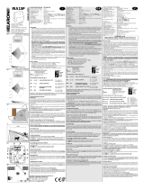
Typical Ind. LuNAR 200DTG3 detection coverage and installation height, are illustrated below:
Side View
1
2
3
4
5
6
7
8
02468998 6 4 2
0 7 13 20 26 3030 26 20 13 7
8.6m/28ft Installation height
m
ft
m
Top View
02468998642
0 7 13 20 26 3030 26 20 13 7
18m/60"
m
ft
NOTE:
When installing the Ind. LuNAR 200DTG3 detector in a
room occupied with high volume interfering elements,
MW detection may be affected.
English

Ind. LuNAR 200DTG3 Installation Guide 8
Installation Process:
To open the detector (Figure 1), remove the cover by inserting a screwdriver (1) in the recess
between the detector’s protection cap and the cover. The cover will remain attached to the base of
the detector.
Using a Philips screwdriver, release the upper cover screw (2) and gently pull upward the detector’s
upper cover.
FIGURE 1
1
2

Ind. LuNAR 200DTG3 Installation
Guide 9
Release the PCB holding screw (Figure 2) located on the right hand side of the PCB (1), pull gently
the two release clips (2) outward and remove the PCB.
Do not touch
the PIR
sensors!
FIGURE 2
English

Ind. LuNAR 200DTG3 Installation Guide 10
If required, open (Figure 3) the wiring channels knockout using a cutter (1, 2) and knockout holes in
the rear cover (3, 4) using a screwdriver.
FIGURE 3
3 4

Ind. LuNAR 200DTG3 Installation
Guide 11
Insert the cable via the cable opening (Figure 4) and connect the desired wires as described in
“Step 4- Wiring”.
Mount the rear cover in its final location (Figure 5) using the 3 mounting screws and seal the
remaining open holes with sealant.
NOTE:
When a single gang box is used, use 2 additional
screws to mount the base to the single gang box.
The back tamper cannot be used in this case!
Return the PCB to its previous location and verify that it is well secured by the holding clips and the
screw.
FIGURE 4
Back
Tamper
Hole
FIGURE 5
English

Ind. LuNAR 200DTG3 Installation Guide 12
Perform lens adjustment and DIP switch settings as described in “Lens Adjustment” on page 12
and on page 15.
Mount the top cover on the detector’s base.
Tighten the top cover’s central screw.
Replace the detector’s protection cap.
NOTE:
If ceiling tamper is desired, break and open the ceiling
tamper hole at the detector’s base!
Lens Adjustment:
The Ind. LuNAR 200DTG3 has three - Fresnel lenses attached to the cover, located in sensor
protective sleeves. Adjust the position of the lenses based on the ceiling mounting height as follows:
Press the 2 clips attaching the sleeve (Figure 6) to the detector’s cover, and gently pull out the
sleeve.
Remove the lens from the sleeve (Figure 7) by gently lifting it from the holding pins that secure it to
the sides of the sleeve.
FIGURE 6

Ind. LuNAR 200DTG3 Installation
Guide 13
Place the two pins, which are located on both sides of the sleeve into the matching slots on the lens.
Use the following table to select the desired lens position.
Return the protective sleeve back into place on the detector front cover.
Repeat steps 1 to 5 for the remaining 2 lenses.
FIGURE 7
English

Ind. LuNAR 200DTG3 Installation Guide 14
NOTES:
Below 3.7m mounting height, the coverage diameter
starts decreasing, and at 2.7m height coverage
diameter is 15m (50ft).
For customized coverage, it is possible to set the
position of each lens to a different height, according to
the installation conditions.
TAMPER EOL
J3
1K
2.2K
4.7K
6.8K
5.6K
J3
ALARM
EOL
AM EOL
RC/SET INPUT
0V
12V
MIN MAX
ON
12345678
9
MW
Potentiometer
PIR
DO NOT TOUCH PIR
SENSORS
1234567
N/A
BUS
MODE
BUS ADDRESS
1
2
34567
ACT LED
Green
Line
Self
Test
AM
RELAY
MODE
REMOTE
CONTROL
DIPswitch Settings
Relay Mode
Configuration
BUS Mode
Configuration
8
9
8
9
N/A N/A
TAMPER

Ind. LuNAR 200DTG3 Installation
Guide 15
Selectors and Jumpers
Used to determine the polarity of the external inputs.
12V: 12v has to be connected in order activate the function.
GND or N.C. has no influence on the RC/SET status.
(see Relay mode DIP switches configuration)
RC/SET
INPUT
0V: The GND has to be connected in order to activate the function.
12v or N.C. has no influence on the RC/SET status.
(see Relay mode DIP switches configuration)
English

Ind. LuNAR 200DTG3 Installation Guide 16
EOL
RESISTORS
JUMPERS
FAULT/AM EOL
JUMPERS
12K
No
Resistor
(Default)
The jumpers are used when connecting the
detector to a DEOL or TEOL Zone. The jumpers
allow the selection of TAMPER, ALARM E.O.L
resistors (1K, 2.2K, 4.7K, 5.6K or 6.8K), according
to the control panel settings. An additional double
jumper allows the connection of 12K FAULT/AM
E.O.L resistor (see EOL Resistors Schematic).
Follow the terminal block connection diagram
when connecting the detector to a Double/Triple
End Of Line (DEOL/TEOL) Zone.
Schematic of EOL Resistors
DIP Switch Settings
The Ind. LuNAR 200DTG3 has a 9 position DIP switch that changes functionality for use in Relay
mode or in BUS operation mode. Set the DIP switch according to the tables below:
Factory Default Settings:
123456789
ON

Ind. LuNAR 200DTG3 Installation
Guide 17
Relay Mode Configuration (DIP
switch 6=OFF)
:
DIP switch
Number
Description
1
Used to determine the operation of the ACT
DIP switch ON: ACT is enabled
DIP switch OFF: ACT is disabled (default factory)
2
Used to determine the operation of the detector’s LEDs
Dip switch ON: LEDs are enabled (default factory)
DIP switch OFF: LEDs are disabled
3
Used to determine the operation of the "Green Line" (See Note below)
DIP switch ON: "Green Line" is enabled
DIP switch OFF: "Green Line" is disabled (default factory)
4
Used to determine the type of Self Test (See Note below)
DIP switch ON: Local Self Test:
In case the local self test fails, the FAULT/AM Relay is activated for a period of 2.5 secs.
DIP switch OFF: Remote Self Test (default factory):
In case the remote self test passes, the Alarm Relays are activated for a period of 5 secs.
In case the test fails, FAULT/AM Relay is activated for a period of 2.5 seconds.
5
Used to determine whether Active IR Anti-Masking is active. (See Note below)
DIP switch ON: Enable
DIP switch OFF: Disable (default factory)
IMPORTANT:
If the AM is enabled via DIP Switch 5, the cover must be fitted within 1 minute from applying the
power. If the detector is already powered up and DIP Switch 5 is turned on, the unit must be
down powered to reset the AM calibration.
Used to determine the detector’s connection mode
6
DIP switch OFF: Relay mode
Used to determine if the Remote Control communication is enabled or disabled.
DIP switch ON: RC communication is always enabled.
7
DIP switch OFF: RC communication depends on the voltage applied to the terminal block
“RC”
(default factory)
When an activation signal is applied to the RC input of the terminal block, RC is enabled.
IMPORTANT:
Turn dipswitch 7 “OFF” after installation and when leaving the site for security reasons. This
will prevent unauthorized use of a remote control unit that may be used to disable the detector.
8-9 DIP switches OFF
NOTE:
See Set Terminal Blocks for activation details.
English

Ind. LuNAR 200DTG3 Installation Guide 18
BUS Mode Configuration (DIP
switch 6=ON):
12
3
4
5
6
7
N/A
BUS
MODE
BUS ADDRESS
8
9
TAMPER
ON
DIP
switch
Number
Description
1-5
Used to set the detector ID number. (See Table 1)
Set the ID number in the same way as for any other ProSYS accessory.
Used to determine the detector’s connection mode.
6
DIP switch ON: ProSYS connection – BUS configuration
NOTE:
Upon power up or normal operation, the Ind. LuNAR 200DTG3 waits 10 seconds for ProSYS
communication. Communication problem may occur due to bad wiring, wrong address, or ProSYS
not configured properly; RED LEDs will continuously flash until the problem is solved.
7
Not applicable (RC communication is automatically enabled when entering Walk Test mode in
the ProSYS and disabled otherwise).
8-9
DIP Switch ON: in order to enable the detector to report the tamper status to ProSYS.
Table 1: ID Settings for BUS connection
ID 1 2 3 4 5 ID 1 2 3 4 5
01
OFF OFF OFF OFF OFF
17
OFF OFF OFF OFF ON
02
ON OFF OFF OFF OFF
18
ON OFF OFF OFF ON
03
OFF ON OFF OFF OFF
19
OFF ON OFF OFF ON
04
ON ON OFF OFF OFF
20
ON ON OFF OFF ON
05
OFF OFF ON OFF OFF
21
OFF OFF ON OFF ON
06
ON OFF ON OFF OFF
22
ON OFF ON OFF ON
07
OFF ON ON OFF OFF
23
OFF ON ON OFF ON
08
ON ON ON OFF OFF
24
ON ON ON OFF ON
09
OFF OFF OFF ON OFF
25
OFF OFF OFF ON ON
10
ON OFF OFF ON OFF
26
ON OFF OFF ON ON
11
OFF ON OFF ON OFF
27
OFF ON OFF ON ON
12
ON ON OFF ON OFF
28
ON ON OFF ON ON
13
OFF OFF ON ON OFF
29
OFF OFF ON ON ON
14
ON OFF ON ON OFF
30
ON OFF ON ON ON
15
OFF ON ON ON OFF
31
OFF ON ON ON ON
16
ON ON ON ON OFF
32
ON ON ON ON ON
1/144