
Underoor heating system
INSTRUCTION & INSTALLATION GUIDE
Instructions in English
Instrucciones en Español
Instructions en Français
Instruções em Português
3
15
27
39
ERKO foil

2

3
IMPORTANT
Read this manual before attempting to install your heating mat. Incorrect installation
could damage the heating mat and will invalidate your warranty.
Contents
1.
Technical information.................................................................................................................................................................4
2.
Recommendations......................................................................................................................................................................5
3.
Materials needed for installation............................................................................................................................................6
4.
Compatible wood laminates.....................................................................................................................................................6
5.
Compatible insulation materials..............................................................................................................................................6
6.
How to select the correct size...................................................................................................................................................6
7.
Testing the heating mat.............................................................................................................................................................7
8.
Electrical safety considerations...............................................................................................................................................7
9.
How to modify the mat.............................................................................................................................................................8
10.
Installation Examples..................................................................................................................................................................8
11.
Installing the mat........................................................................................................................................................................9
12.
Warranty......................................................................................................................................................................................11
13.
Control card.................................................................................................................................................................................12
14.
Documentation of ownership, installation and electrical connection.............................................................................13
Underoor heating system
WARNING
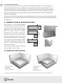
The oor heating mat has been designed so that installation is quick and straight forward, but as
with all electrical systems, certain procedures must be strictly followed. Please ensure that you
have the correct heating mat(s) for the area you wish to heat. The manufacturer of the heating mat,
accepts no liability, expressed or implied, for any loss or consequential damage suered as a result
of installations which in any way contravene the instructions that follow.
It is important that before, during and after installation that all requirements are met and understood.
If the instructions are followed, you should have no problems. If you do require help at any stage,
please contact our helpline:
T (UK): 0203 321 5929 T (IE): 015 530 526
EN
ERKO foil

4
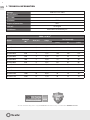
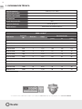
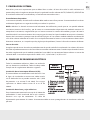
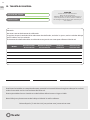
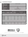
1. TECHNICAL INFORMATION
Voltage 230V AC ±15% 50Hz
Mat thickness 1mm
Mat width 50cm
Insulation ETFE
Degree of protection IPX7
Cold tail 3m length
Certicates Declaration of conformity CE
ERKO 140 W/m
2
Model
Wattage
(W)
Area (m
2
) Amps
Resistance (Ω)
(-5%) Ω (+5%)
MSIWFH010 140 1 0,61 359 378 397
MSIWFH015 210 1,5 0,91 239 252 265
MSIWFH020 280 2 1,22 180 189 198
MSIWFH030 420 3 1,83 120 126 132
MSIWFH040 560 4 2,43 89 94 99
MSIWFH050 700 5 3,04 72 76 80
MSIWFH060 840 6 3,65 60 63 66
MSIWFH070 980 7 4,26 51 54 57
MSIWFH080 1.120 8 4,87 45 47 49
MSIWFH090 1.260 9 5,48 40 42 44
MSIWFH100 1.400 10 6,09 36 38 40
MSIWFH120 1.680 12 7,30 30 32 34
*The Rointe underfllor heating systems comply with ECODESIGN standards when they are installed with the ROINTE thermostats.
*
EN

5
EN
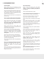
2. RECOMMENDATIONS
Recommended Not recommended
Always check with the manufacturer of the
ooring that their products are compatible with
electric oor heating systems.
Always operate the heating foil with a thermostat
in oor sensor mode, to ensure the oor does
not exceed the maximum temperature of the
wood laminate (usually 27°C).
Always ensure all earth leads are connected to
the earth ring.
Always connect all cold wire leads from the foil
mats in parallel inside an electrical junction box.
Always zone each room with a foil heating
system with its own thermostat controller,
allowing each room to be controlled individually
and saving energy. Each thermostat has a
maximum capacity of 16A.
Always ensure that no sharp edges (e.g.
metaledged laminate locking systems) come in
contact with the heating foil.
Always install a soft insulation below the foils
to prevent damage when the weight of the oor
furniture is added. Make sure unavoidable
wooden oor movements will not harm the
heating foils.
Always ensure that a heat loss calculation has
been carried out and heating requirements
have been met if you are installing the system as
a primary source of heating.
Always ensure that the systems are protected by
a 30mA RCD.
Always ensure that the control card at the end of
the manual is completed and xed at the main
consumer unit along with any plans and
electrical test records, as per the current
regulations.
Always use the foil strips provided to bridge any
gaps when cutting and turning the foil mats, to
keep the earth intact.
Don’t use the foil heating mats with glued
locking systems or laminates that have an
underpad or cushion material pre-attached to
its underside.
Don’t install the foil heater up steps.
Don’t install over oors that are uneven or have
traces of moisture, carpets or parquet oor.
Don’t leave insulating materials such as bean
bags, linen or towels on the oor surface.
Don’t overlap, fold or wrinkle the foil heating
mats.
Don’t place heavy/sharp tools (or any other
potentially damaging object) on top of the foils.
Don’t walk unnecessarily over the foil mats.
Don’t install foil heating mats when the room
temperature is below -5ºC.
Don’t install foil heating mats anywhere except
inside buildings.
Don’t install foil mats under walls or partitions,
or in areas under heavy cabinets, closets, or
xtures (toilets, sinks, tubs, etc.).
Don’t install foil mats within approximately
50mm of any heat conductive building part,
such as cold water pipes.
Don’t install foil mats within 20mm of one
another, 50mm of any wall or 100mm of a
replace or hot water pipe.
Don’t install foil heating mats under any oor
covering other than wood or laminate or
wooden oors thicker than 18mm.
Don’t place items on the oor surface which will
stop the air ow or not allow heat to rise into the
room.
Don’t install electrical cables or pipes under the
oor with the foil heating mats.
Don’t install the heating foils in direct contact
with a cement or concrete slab.

6
3. MATERIALES NECESARIOS
Components included in your Rointe heating foil kit:
• ERKO foil.
• Installation manual.
Before installing the foil heating system, be sure that you have the following additional parts:
• Customized installation plan (or layout).
• Thermostat.
• Digital ohm meter (multi-meter).
• 30mA RCD.
• Electrical junction box.
• Electrical conduit.
• Insulation material.
• Duct tape (optional).
4. COMPATIBLE WOOD LAMINATES
Please ensure that the laminate ooring is suitable for use with electric underoor heating.
Most wood / laminate oors are compatible with the foil mats but we do not recommend using any wood
ooring thicker than 18mm.
Wood ooring with metallic strips as part of their locking systems are NOT compatible as these metallic
strips may damage the foil mats.
Any wood oor with a pad already attached must not be used with the foil mats.
For wooden oors or similar the thermal resistance should not exceed 0.15m2K/W.
5. COMPATIBLE INSULATION MATERIALS
The foil heaters MUST NOT be installed in thinset cement or in direct contact with a cement or concrete
suboor. The heater MUST be installed on top of a suitable soft insulation material. This is necessary to
prevent the heater from being damaged when the weight of the oor furniture and people are added.
The insulation material should be at least 6mm thick and suitable for use with electric underoor heating.
It is important that you take into account the insulation properties, the better R value the shorter the heat
up time.
If using the insulation board or similar, a soft underlay must be used to ensure the heater is not in contact
with the cement facing of the board.
NOTE: Underlayment papers are not compatible with the foil heating mats.
6. HOW TO SELECT THE CORRECT SIZE
Calculate the area of the oor to be heated. This is the total oor area minus any permanent xtures.
area = length x width = m
2
Select the heating foil or combination of foils closest in size to the area you want to heat. See page 4 for
the full range of sizes. Remember:
• Heaters cannot overlap
• Heaters must be connected in parallel
• A single thermostat can control up to handle loads up to 16 Amps
EN

7
6. TESTING THE HEATING MAT
The heating mats must be tested before, during and after tiling. We recommend the use of a digital multimeter
set to a range of 0-2 KΩ for testing. The resistance (Ω) of each mat should be measured. You should carry out
the following tests and should expect the results detailed below:
• Live to neutral should show the resistance value listed in the table on page 4. A ± 5% Ohm reading
tolerance is allowed under manufacturing guidelines. Record the readings on the control card at the
back of the manual.
• Live to earth and neutral to earth should show innity.
NOTE: Due to the high resistance of the heating element, it may not be possible to get a continuity reading
from the mat and as such, continuity testers are not recommended. When checking resistance, make sure
your hands do not touch the meter’s probes as the measurement will include your internal body resistance
and render the measurement inaccurate. If you do not get the expected results or at any time you believe
there may be a problem, please contact our helpline for guidance.
Floor Sensor
Ensure that the oor sensor is tested before the nal oor nish has been laid. The oor sensor values can
be found in the thermostat instructions. When testing the oor sensor ensure that the meter can read up
to 20kΩ. Rointe thermostats use a 10kΩ oor sensor. The expected resistance is: 10kΩ at 25°C, 12.1kΩ at 20°C,
14.7kΩ at 15°C.
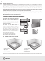
7. ELECTRICAL SAFETY CONSIDERATIONS
All electrical connections must be undertaken by a certied electrician. All work must conform to current
Electrical Regulations. The electric oor heating
System must be controlled via a room thermostat at
all times.
Installing a Residual Current Device (RCD)
The Heating Mats must be wired via an 30mA RCD.
A dedicated RCD must be installed if one is not already
present. No more than 7.5kW of heating may be
connected to a single 30mA RCD.
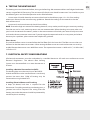
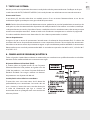
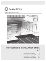
Installing Electrical Boxes and Trunking
A deep (35-40mm) back box is required for the
thermostat. If installing more than two heating mats, a
junction box will be required. The wiring from the
heating mat to the thermostat should be protected by
conduit or plastic trunking.
A
B
C
D
E
EN

8
Connecting the Thermostat
The thermostat should be installed within the room to be heated. In most bathroom installations the
thermostat cannot be located within the bathroom itself as the thermostat could be IP20 rated and must
be located outside of Zone 2. In such cases the thermostat must be tted to the outside of an internal wall
of the bathroom, as close to the installation as possible. Rointe thermostats are rated up to 16A. For larger
installations exceeding 16A multiple thermostats or a suitable contactor will be required. For further advice
contact Rointe.
Once the electrical connections have been made and the system has been tested, the electrician must
complete the control card at the end of this installation manual. This information must be displayed at or
near the consumer unit.
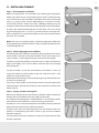
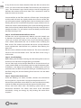
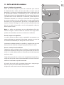
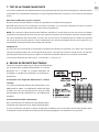
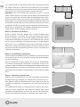
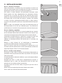
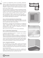
8. HOW TO MODIFY THE MAT
In some instances, you may need to cut
turn and ip the mat to suit the room.
It is essential that you do not cut, twist
or kink the heating wire. To make a cut
separate the foil sheets at the long edge
of the heater to expose the heating cable
loops. Lift the cable out of the way when
cutting. Once aluminium foil has been cut
and the mat has been repositioned, use
the aluminium foil strips provided to cover
the exposed cable and link the pieces of
the mat. If required, use duct tape to hold
mats in position.
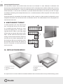
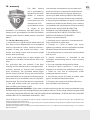
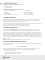
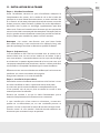
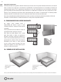
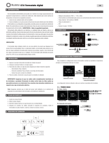
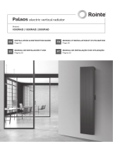
10. INSTALLATION EXAMPLES
If a vapour barrier is to be installed it should be laid below the insulation and not on top of the heating system.
EN
1. Wood/laminate ooring.
2. Foil heater.
3. Soft insulation material.
4. Suboor.
1. Wood/laminate ooring.
2. Foil heater.
3. Underlay.
4. Insulation board.
5. Suboor.

9
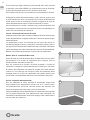
11. INSTALLING THE MAT
Step 1 - Planning the installation
Before installing, draw an installation plan showing the placement
of the mats, oor sensor, and junction box or boxes. The foil heating
mats should cover at least 80-90% of the oor area of the room to be
used as a primary heat source (depending on insulation, air-ow
and overall heat-loss within the room, additional heating may be
required). Choose the combination of heating foils that best enables
to cover the recommended 80-90% of the room. Plan to use the
larger foil heating mats as much as possible and to use smaller foils
only as gap llers. It is important to keep an accurate record of where
the mats are installed.
Note: The mats are supplied with a 3 metre long electrical cold lead.
If you need longer connection leads, these may be extended consult
a qualied electrician.
Step 2 - Check and prepare the suboor
The heating foil MUST NOT be installed in thinset cement, or in direct
contact with a cement or concrete suboor. There must always be a
soft insulation / underlay beneath the aluminium heating foils.
Carefully inspect the suboor and make sure it is clean, free of sharp
edges, protruding nails and any other materials that may damage
the heating foil.
Lay the insulation as per the manufacturer instructions. If you are
using the Rointe insulation board you will need to install a soft
underlay on top of the boards.
Remove the foil heating mat from the packaging and check the mats
visually for any damage.
Test using a multi-meter and verify the correct resistance against the
table on page 4. Record the readings on the control card at the back
of the manual.
Step 3 - Laying out the heating foils
Roll out the heating foil on top of the insulation material. Keep the
heating foil at least 50mm from the edges of the room.
Ensure that the heating foil is completely at. Care should be taken
not to fold or crease the foils at any time during installation.
Position it in such a way that the power cord will be able to reach the
point where the thermostat will be connected.
If tting more than one heating foil ensure that the foil does not
overlap, as overheating will result. Leave a gap of at least 20mm
between each foil.
Secure the foil mat to the underlay using tabs of duct tape to hold
the foil in position.
EN
2
3

10
If any of the wire has been detached from the foil mat (when the
mat is cut and turned) the wire MUST be covered by the aluminium
strips. The aluminium strips should also be used to bridge the gap
between the sections of the mat. Note: This is essential in order to
keep the earth circuit intact.
Secure the foils to the oor with tabs of duct tape. Since the joint
and the cold tail leads are slightly thicker than the rest of the foil,
you will need to create a slight groove in the insulation to ensure the
heating foil lays at. Do not allow the power supply cable to cross or
come into contact with the heating foil. Once the heating foil have
been laid mark each coldtail lead coming from the same foil with a
numbered sticker. This will make it easier to identify each foil once
the oor covering is laid.
Step 4 - Install the thermostat oor sensor
Position the sensor approximately 300mm into the heated area
in-between the heating wires runs on the foil. Do not allow the
sensor tip to come into contact with any of the heating element
wires. Rointe recommend the use of conduit when installing the
oor sensor. The conduit will protect the sensor and will allow for
easier replacement should there be a problem after ooring has
been laid.
Run the sensor cable back to the thermostat. The sensor wire MUST
not cross over the foil heater wires. Test the oor sensor using a
multi-meter.
Step 5 - Install the oor
Before tting the nal oor covering test the heating foils to ensure
that they have not been damaged during installation.
You are now ready to lay the nal oor nish. Do not drive nails or
screws into the oor or cut the oor panels on top of the heating foil.
If the oor is not being laid immediately, all heating foils must be
protected with cardboard to prevent damage. Immediately prior to
the oor being laid, test the heating foil to ensure it has not been
damaged.
Step 6 - Connect the thermostat
Once the ooring has been installed, connect the thermostat
ensuring that it is set to reach a maximum temperature of 27°C.
A thermostat with a oor sensor MUST be used in order to accurately
monitor the oor temperature and the required comfort level.
Always zone each room with a foil heating system with its own
thermostat controller. This allows each room to be controlled
individually saving you energy by only heating the zone when
required.
EN
4
5

11
10. warranty
The oor heating
mat is guaranteed by
Rointe to be free from
defects in materials
and workmanship
under normal use and
maintenance, and is
guaranteed to remain
so subject to the
limitations and conditions described below. The
heating mat is guaranteed for 10 YEARS for the oor
covering under which it is tted, except as provided
below.
This 10 Years Warranty applies:
1. only if the unit is registered with Rointe within 30
days after purchase. Registration can be completed
online. In the event of a claim, proof of purchase is
required, so keep your invoice and receipt - such
invoice and receipt should state the exact model
that has been purchased;
2. only if the heating mat has been earthed and
protected by a Residual Current Device (RCD) at all
times.
This guarantee does not continue if the oor
covering over the heating mat(s) is damaged, lifted,
replaced, repaired or covered with subsequent
layers of ooring. The guarantee period begins
on the date of purchase. During the period of the
guarantee Rointe will arrange for the heating mat to
be repaired or (at its discretion) have parts replaced
free of charge. The cost of the repair or replacement
is your only remedy under this guarantee which
does not aect your statutory rights.
Such cost does not extend to any cost other than
direct cost of repair or replacement by Rointe and
does not extend to costs of relaying, replacing or
repairing any oor covering or oor. If the heating
mat fails due to damage caused during installation
or tiling, this guarantee does not apply. It is therefore
important to check that the heating mat is working
(as specied in the installation manual) prior to tiling.
ROINTE SHALL IN NO EVENT BE LIABLE FOR
INCIDENTAL OR CONSEQUENTIAL DAMAGES,
INCLUDING BUT NOT LIMITED TO EXTRA UTILITY
EXPENSES OR DAMAGES TO PROPERTY.
Rointe is not responsible for:
1. Damage or repairs required as a consequence of
faulty installation or application.
2. Damage as a result of oods, res, winds,
lightening, accidents, corrosive atmosphere or other
conditions beyond the control of Rointe.
3. Use of components or accessories not compatible
with this unit.
4. Normal maintenance as described in the
installation and operating manual, such as cleaning
thermostat.
5. Parts not supplied or designated by Rointe.
6. Damage or repairs required as a result of any
improper use, maintenance, operation or servicing.
7. Failure to start due to interruption and/or
inadequate electrical service.
8. Any damage caused by frozen or broken water
pipes in the event of equipment failure.
9. Changes in the appearance of the product that
does not aect its performance.
Replacement Warranty Guidelines: If you make a mistake and damage the new heating mat before laying
the oor covering, return the damaged heating mat to Rointe within in 30 days along with your original dated
sales receipt. Rointe WILL REPLACE ANY PRETILED HEATING MAT (MAXIMUM 1 HEATING MAT) WITH ANOTHER
HEATING MAT OF THE SAME MAKE AND MODEL - FREE.
(i) Repaired heating mats carry a 5 year warranty only. Under no circumstances is Rointe responsible for the repair or replacement of any tiles / oor covering which may be
removed or damaged in order to aect the repair.
(ii) The Replacement Guarantee does not cover any other type of damage, misuse or improper installation due to improper adhesive or suboor conditions. Limit of one free
replacement heating mat per customer or installer.
(iii) Damage to the heating mat that occurs after tiling, such as lifting a damaged tile once it has set, or suboor movement causing oor damage, is not covered by the
Replacement Guarantee.
EN

12
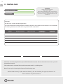
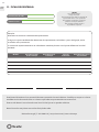
11. CONTROL CARD
Date Signed Name or company stamp
Attention:
Do not cut or shorten the heating element.
Ensure that the entire heating elements including the joints are installed under the tiles in the installation.
The heating element must be used in conjunction with a 30mA RCD.
Model Resistance before Resistance after
Insulation
resistance pass
Floor sensor
resistance
CAUTION
Electric oor heating systems.
Risk of electric shock.
Electric wiring and heating panels contained below
the oor. Do not penetrate with nails, screws, or similar
devices. Do not restrict the thermal emission of the
heated oor.
This form must be completed as part of the Rointe Guarantee. Ensure that the values are as per the
instruction manual.
This card must be situated close to the consumer unit in a visible place.
Note: Draw a plan showing the layout of the heating mat.
Rointe UK & Ireland | T (UK): 0203 321 5929 | T (IE): 015 530 526 | E: support@rointe.co.uk
www.rointe.co.uk | www.rointe.ie
Heating mat location
Total wattage
EN

13
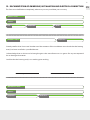
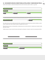
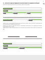
12.
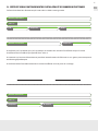
DOCUMENTATION OF OWNERSHIP, INSTALLATION AND ELECTRICAL CONNECTION
This form must be lled out completely, otherwise you may invalidate your warranty.
I hereby conrm that I have read & understand the contents of the installation manual and that the heating
mat(s) has been installed as specied therein.
I acknowledge that no claim can be brought against the manufacturer or its agents for any consequential
loss or damage whatsoever.
I conrm that the heating mat(s) was working prior to tiling.
Owner’s name
Electrician’s name
Installer’s name
Address
Address
P.C.
Telephone
Telephone
License nº
Telephone
Email
Installer’s signature Date
EN

14

15
IMPORTANTE
Lea cuidadosamente este manual antes de instalar la malla radiante. Una instalación incorrecta
podría dañar el calefactor e invalidará la garantía.
Contenido
1.
Información técnica ..................................................................................................................................................................16
2.
Recomendaciones.....................................................................................................................................................................17
3.
Materiales necesarios................................................................................................................................................................18
4.
Suelos compatibles...................................................................................................................................................................18
5.
Aislantes compatibles...............................................................................................................................................................18
6.
Elegir el tamaño correcto de la malla.........................................................................................................................................18
7.
Pruebas del sistema...................................................................................................................................................................19
8.
Consejos de seguridad eléctrica............................................................................................................................................19
9.
Modicar la malla radiante......................................................................................................................................................20
10.
Ejemplo de instalación.............................................................................................................................................................20
11.
Instalación de malla radiante..................................................................................................................................................21
12.
Garantía.......................................................................................................................................................................................23
13.
Tarjeta de control.......................................................................................................................................................................24
14.
Documentación del propietario............................................................................................................................................25
Sistema de calefacción por suelo radiante
ERKO foil
ATENCIÓN
El fabricante de la malla radiante no acepta responsabilidad alguna, expresa ni implícita, por cualquier
pérdida o daño derivado sufrido a raíz de instalaciones que de cualquier forma contravengan lo
expuesto en las siguientes instrucciones.
Si se siguen estas instrucciones, no tendrán ningún tipo de problema. Sin embargo, si necestia ayuda
llame a nuestra línea de asistencia:
902 130 134
ES

16
1. INFORMACIÓN TÉCNICA
Tensión nominal 230V AC ±15% 50Hz
Espesor de la malla 1mm
Anchura de la malla 50cm
Aislamiento ETFE
Grado de protección IPX7
Cola fría (Cold tail) 3m de longitud
Aprobaciones Declaración de conformidad CE
ERKO 140 W/m
2
Referencia
Potencia
(W)
Área (m
2
) Amps
Resistencia (Ω)
(-5%) Ω (+5%)
MSNWFH010 140 1 0,61 359 378 397
MSNWFH015 210 1,5 0,91 239 252 265
MSNWFH020 280 2 1,22 180 189 198
MSNWFH030 420 3 1,83 120 126 132
MSNWFH040 560 4 2,43 89 94 99
MSNWFH050 700 5 3,04 72 76 80
MSNWFH060 840 6 3,65 60 63 66
MSNWFH070 980 7 4,26 51 54 57
MSNWFH080 1.120 8 4,87 45 47 49
MSNWFH090 1.260 9 5,48 40 42 44
MSNWFH100 1.400 10 6,09 36 38 40
MSNWFH120 1.680 12 7,30 30 32 34
*Los sistemas de suelo radiante Rointe cumplen con la normativa de ECODISEÑO siempre que sean instalados con los termostatos ROINTE.
*
ES

17
2. RECOMENDACIONES
Se recomienda No se recomienda
Asegúrese de que todas las conexiones a tierra
son correctamente realizadas.
Asegúrese de que el circuito eléctrico que
proporciona energía al sistema de calefacción
de mallas radiantes para suelos laminados
está equipado con un dispositivo de corriente
residual de 30mA.
Se recomienda conectar siempre todas las
conexiones frías de las mallas radiantes para
suelos laminados en paralelo dentro de una o
varias cajas de derivación.
Asegúrese de que el total de corriente requerida
para todas las mallas conectadas en paralelo
no supera el 80% de la capacidad de amperaje
indicada para la caja eléctrica de derivación,
su línea de suministro eléctrico y su disyuntor.
(Para más información, póngase en contacto
con un instalador o proveedor profesional).
Se recomienda instalar una caja eléctrica de
derivación y un termostato de control para cada
una de las habitaciones. Cada termostato Rointe
tiene una capacidad máxima de 16 amperios. Si
el total de amperios en una sola habitación es
superior a 16A, reparta el amperaje entre varios
termostatos (Para calcular el total de amperios,
consulte la tabla de la página 16).
Se recomienda utilizar siempre planchas termo
aislantes debajo del sistema de calefacción para
reducir costes de funcionamiento y el tiempo de
calentamiento.
Asegúrese siempre de que ningún objeto alado
(por ejemplo sistemas de encaje metálicos del
suelo otante) se queda en contacto con el
sistema de calefacción.
No superponga las mallas radiantes.
No doble o retuerza las mallas radiantes para
suelos laminados.
No coloque herramientas pesadas o aladas (o
cualquier otro objeto potencialmente peligroso)
sobre las mallas radiantes.
No camine sobre las mallas radiantes a no ser
que sea estrictamente necesario.
No instale cables eléctricos o tuberías bajo el
suelo junto a las mallas radiantes.
No utilice un aislante de celulosa.
No instale las mallas cuando la temperatura de
la habitación sea inferior a - 5º C.
No instale las mallas radiantes en espacios al aire
libre.
No instale mallas bajo paredes y tabiques o en
áreas que soporten el peso de muebles, armarios
o sanitarios (inodoros, lavabos, bañeras, etc.).
No instale mallas a menos de 30mm de
cualquier elemento conductor de calor, por
ejemplo, tuberías de agua caliente.
No instale mallas a menos de 10mm de otra
malla, a menos de 50mm de una pared ni a
menos de 150mm de una chimenea o una
tubería de agua caliente.
No conecte ningún aparato eléctrico en la
misma línea en derivación con fusible ni en
el mismo interruptor del circuito de fallos de
conexión a tierra.
No instale mallas bajo suelo de madera si éste
tiene un grosor superior a 18mm.
No coloque material de aislamiento acústico
entre las mallas radiantes y el suelo de madera
cuando proceda a la instalación de suelos de
madera.
ES

18
3. MATERIALES NECESARIOS
Componentes que incluye su kit de malla radiante:
• Malla radiante ERKO.
• Manual de instalación.
Componentes que NO incluye su kit de malla radiante:
• Planta de distribución de la malla.
• Termostato.
• Multímetro digital.
• Disyuntor diferencial residual de 30 mA.
• Caja(s) eléctrica(s).
• Conducto(s) eléctricos(s).
• Material de aislamiento.
• Cinta adhesiva (opcional).
4. SUELOS COMPATIBLES
Asegúrese de que el suelo laminado elegido es adecuado para su uso con calefacción de suelo radiante
eléctrico. La mayoría de los suelos laminados o de madera son compatibles con este sistema, pero se
recomienda no utilizar ningún parquet más grueso que 18 mm.
Suelos de madera que contienen piezas de metal como parte del sistema de encaje no son compatibles, ya
que estas piezas de metal están en alto riesgo y pueden dañar el sistema.
Asegúrese de que la resistencia térmica de la planta no exceda 0.15m2K/W.
5. AISLANTES COMPATIBLES
Las mallas radiantes NO DEBEN instalarse en el cemento o en contacto directo con un substrato de
cemento o hormigón. La malla DEBE instalarse encima de un material de aislamiento suave adecuado.
Esto es necesario para evitar que la malla se dañe con el peso de los muebles en el suelo y de las personas.
El material aislante debe ser de al menos 6 mm de espesor y adecuado para su uso con calefacción eléctrica
por suelo radiante. Es importante que tenga en cuenta las propiedades de aislamiento, cuanto mejor sea
el valor R, más corto será el tiempo de calentamiento. Si se utiliza plancha aislante o similar, debe utilizarse
una manta aislante blanda para asegurar que la malla radiante no esté en contacto con el recubrimiento de
cemento de la placa.
NOTA: Los underlays de papel no son compatibles con las mallas radiantes.
6. ELEGIR EL TAMAÑO CORRECTO DE LA MALLA
Calcular el área a calentar. El área a ser calentada es el área total menos el espacio ocupado por objetos jos
tales como armarios, etc.
area = largo x ancho = m
2
Elija el tamaño de la malla que mejor coincida con el área a ser calentada (consejo: calcule para el 90%
del área). Vea la tabla de la página 16 para una gama completa de tamaños. Recuerde:
• Las mallas no se pueden cruzar
• Las mallas deben estar conectadas en paralelo
• Cada termostato puede controlar hasta 16A
ES

19
7. PRUEBAS DEL SISTEMA
Uno de los pasos más importantes que se deben llevar a cabo a la hora de instalar la malla radiante es el
proceso de prueba. Asegúrese siempre de que ha probado la malla radiante ANTES, DURANTE y DESPUÉS de
la instalación utilizando un multímetro y un enchufe con conexión a tierra.
Procedimiento de pruebas
La resistencia (ohmios) de cada malla radiante debe medirse entre fase y neutro. Se recomienda el uso de un
multímetro digital con un rango de 0 a 2kΩ para realizar las pruebas.
NOTA: debido a la elevada resistencia del elemento de calefacción, puede que no sea posible obtener
una lectura continua de la malla y, por lo tanto, no se recomiendan dispositivos de medición continua. Al
comprobar la resistencia, asegúrese de que sus manos no tocan las sondas del medidor, ya que si lo hace la
medida incluirá la resistencia interna de su cuerpo y, por lo tanto, hará que la medida no sea precisa. Anote las
lecturas de la resistencia y compare con la tabla de la página 16. Los valores medidos deben estar dentro del
±5% de los valores indicados en la tabla. Si en cualquier momento las lecturas no se encuentran dentro de las
directrices anteriores, o si sospecha que hay algún tipo de problema, llame a la línea de asistencia de Rointe.
Sensor de suelo
Asegúrese que el sensor de suelo sea probado antes de que el suelo nal sea colocado. Los valores del sensor
de suelo se pueden encontrar en el manual de instrucciones del termostato. Cuando este probando el sensor
de suelo asegúrese de que el medidor puede leer hasta 20kΩ. Los termostatos Rointe utilizan un sensor de
suelo de 10kΩ. La resistencia esperada es: 10kΩ a 25ºC, 12,1kΩ a 20°C, 14,7kΩ a 15ºC.
8. CONSEJOS DE SEGURIDAD ELÉCTRICA
Todas las conexiones eléctricas deben ser realizadas
por un electricista cualicado. Todo el trabajo debe
cumplir con las regulaciones eléctricas vigentes.
Instalación de un interruptor diferencial (ID)
El sistema debe estar conectado a través de un ID. Si en
el lugar de instalación no existe uno, debe instalar
un ID dedicado. No se pueden conectar más 7,5KW
de potencia a un mismo ID de 30mA. Para cargas
superiores se deben utilizar varios ID o un ID de
100mA.
Instalación de enlaces y cajas eléctricas
Para el termostato necesitará una caja de 35-40mm de
profundidad. Si está instalando dos o más sistemas,
ecesitará una caja de conexiones. El cable de
alimentación que conecta el sistema al termostato debe ser estar protegido con un conducto o tubo de
plástico.
A
B
C
D
E
ES

20
Conexión del termostato
El termostato debe ser conectado a la red de alimentación a través de un ID, de acuerdo con las normas
vigentes, por un electricista calicado. El termostato debe instalarse dentro de la habitación o área que
desea calefactar; sin embargo, en el caso de instalaciones en baños, se recomienda que el termostato se
coloque en el exterior de una pared interna del baño, lo más cerca posible del sistema de suelo radiante. Los
termostatos Rointe están diseñados para cargas hasta 16A. Para instalaciones que excedan 16A, se requieren
múltiples termostatos o un contactor. Para más consejos contacte con Rointe.
Una vez que se han realizado las conexiones eléctricas y el sistema ha sido probado, el electricista debe
completar la tarjeta de control ubicada en la parte posterior de este manual de instalación. Esta información
debe disponerse cerca de la unidad de consumo.
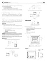
9. MODIFICACIÓN DE LA MALLA RADIANTE
En algunos casos podrá tener necesidad
de cortar y girar la malla radiante para
adecuarla al espacio a calentar. Es vital que
no corte o torsione el cable de calefacción
en ninguna situación.
Para hacer un corte deberá darle la
vuelta a la malla por donde las vueltas se
encuentran expuestas. Levante el cable
para realizar el corte. Una vez cortada y
reposicionada la malla, utilice las tiras de
aluminio para cubrir el cable expuesto y
unir las dos partes de la malla.
Si es necesario, use cinta adhesiva
para sujetar las mallas en posición.
10. EJEMPLO DE INSTALACIÓN
En caso de que sea instalada una barrera de vapor, se debe instalar debajo del aislamiento y no por encima de la malla radiante.
ES
1. Suelo nal / laminado.
2. Malla radiante.
3. Aislamiento.
4. Suelo base (hormigón).
1. Suelo nal / laminado.
2. Malla radiante.
3. Underlay.
4. Aislamiento.
5. Suelo base (madera).
A página está carregando...
A página está carregando...
A página está carregando...
A página está carregando...
A página está carregando...
A página está carregando...
A página está carregando...
A página está carregando...
A página está carregando...
A página está carregando...
A página está carregando...
A página está carregando...
A página está carregando...
A página está carregando...
A página está carregando...
A página está carregando...
A página está carregando...
A página está carregando...
A página está carregando...
A página está carregando...
A página está carregando...
A página está carregando...
A página está carregando...
A página está carregando...
A página está carregando...
A página está carregando...
A página está carregando...
A página está carregando...
A página está carregando...
A página está carregando...
A página está carregando...
A página está carregando...
-
 1
1
-
 2
2
-
 3
3
-
 4
4
-
 5
5
-
 6
6
-
 7
7
-
 8
8
-
 9
9
-
 10
10
-
 11
11
-
 12
12
-
 13
13
-
 14
14
-
 15
15
-
 16
16
-
 17
17
-
 18
18
-
 19
19
-
 20
20
-
 21
21
-
 22
22
-
 23
23
-
 24
24
-
 25
25
-
 26
26
-
 27
27
-
 28
28
-
 29
29
-
 30
30
-
 31
31
-
 32
32
-
 33
33
-
 34
34
-
 35
35
-
 36
36
-
 37
37
-
 38
38
-
 39
39
-
 40
40
-
 41
41
-
 42
42
-
 43
43
-
 44
44
-
 45
45
-
 46
46
-
 47
47
-
 48
48
-
 49
49
-
 50
50
-
 51
51
-
 52
52


Rointe Erko Manual do proprietário
- Tipo
- Manual do proprietário
- Este manual também é adequado para
em outras línguas
- español: Rointe Erko El manual del propietario
- français: Rointe Erko Le manuel du propriétaire
- English: Rointe Erko Owner's manual
Artigos relacionados
-
 Rointe Atria Manual do proprietário
-
 Rointe ST.0 analogue thermostat Manual do proprietário
-
 Rointe Bekia Manual do proprietário
-
Rointe CT.2 Manual do proprietário
-
-
 Rointe CT.0 Manual do proprietário
-
 Rointe ST. 2 Manual do proprietário
-
Rointe Termo A.Q.S. Galilea Manual do proprietário
-
 Rointe Palaos radiador elétrico vertical digital 2022 Manual do proprietário


