
Industrial Heat-Tracing
Aquecimento Industrial
Rastreo de calor industrial
Installation and Maintenance Manual for
Series Resistance Heating Cable Systems for Pipes
Manual De Instalação E Manutenção De
Aquecimento Industrial Para Os Sistemas
De Cabo Aquecedor Series Resistance Para Tubos
Manual De Instalación Y Mantenimiento Para
Sistemas De Cable Calefactor De Resistencia
En Serie Para Tuberías

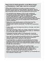
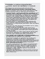
Important Safeguards and Warnings
WARNING: FIRE AND SHOCK HAZARD.
nVent RAYCHEM heat-tracing systems must be
installed correctly to ensure proper operation and to
prevent shock and fire. Read these important warnings
and carefully follow all the installation instructions.
• To minimize the danger of fire from sustained
electrical arcing if the heating cable is damaged
or improperly installed, and to comply with
nVent requirements, agency certifications, and
national electrical codes, ground-fault equipment
protection must be used on each heating cable branch
circuit. Arcing may not be stopped by conventional
circuit breakers.
• Approvals and performance of the heat-tracing
systems are based on the use of approved
components and accessories. Do not use substitute
parts.
• Cable ends must be kept dry before, during, and after
installation.
• Damaged heating cable can cause electrical arcing or
fire. Use only nVent-approved glass tape or cable ties
to secure the cable to the pipe.
• Damaged heating cable or components must be
repaired or replaced. Contact nVent for assistance.
• Use only fire-resistant insulation which is compatible
with the application and the maximum exposure
temperature of the system to be traced.
• To prevent fire or explosion in hazardous locations,
verify that the maximum sheath temperature of the
heating cable is below the autoignition temperature of
the gases in the area. For further information, see the
design documentation.
• Heating cables are capable of reaching high
temperatures during operation and can cause burns
when touched. Avoid contact when cables are
powered. Insulate the pipe before energizing the
cable. Use only properly trained personnel.
• Material Safety Data Sheets (MSDSs) are available on
our website: nVent.com.

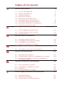
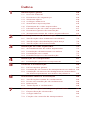
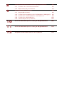
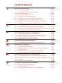
Table of Contents
1
General Information 5
1.1 Use of the Manual 5
1.2 Safety Guidelines 6
1.3 Typical System 6
1.4 Electrical Codes 7
1.5 Warranty and Approvals 7
1.6 Heating Cable Construction 8
1.7 Heating Cable Identification 9
1.8 General Installation Guidelines 10
1.9 Heating Cable Storage 11
2
Heating Cable Verification and Selection 12
2.1 Check Materials Received 12
2.2 Check Piping to be Traced 12
2.3 Check Tools 12
3
Heating Cable Installation 13
3.1 Heating Cable Payout 13
3.2 Installation Directly on Pipes 18
3.3 Installation in Channel 19
3.4 Typical Installation Details 20
4
Heating Cable Components 23
4.1 General Component Installation 23
5
Control and Monitoring 25
5.1 General Information 25
5.2 Temperature Sensor Installation on Pipes 26
5.3 High Temperature Cut-Out Installation
on Plastic Pipes 27
6
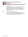
Thermal Insulation and Marking 28
6.1 Pre-Insulation Checks 28
6.2 Insulation Installation Hints 28
6.3 Marking 30
6.4 Post-Insulation Testing 30
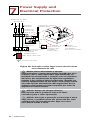
7
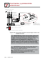
Power Supply and Electrical Protection 31
7.1 Voltage Rating 31
7.2 Electrical Loading 31
7.3 Temperature Control Wiring 33

8
Commissioning and Preventive Maintenance 34
8.1 Commissioning Tests 34
8.2 Preventive Maintenance 35
9
Test Procedures 37
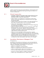
9.1 Visual Inspection 37
9.2 Insulation Resistance (Megger) Test 37
9.3 Resistance and Continuity Test 41
9.4 Capacitance Test 42
9.5 Power Check 44
10
Test Procedures 46
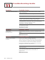
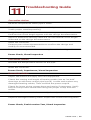
11
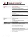
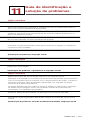
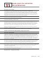
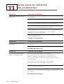
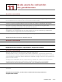
Troubleshooting Guide 52
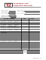
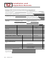
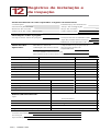
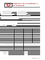
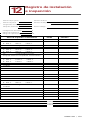
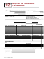
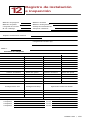
12
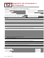
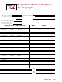
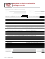
Installation and Inspection Records 56

nVent.com | 5
1
General Information
nVent RAYCHEM Series Resistance SC heat-tracing
systems are for use on thermally insulated metal
and plastic pipes. These systems must be installed
in compliance with requirements established in the
design documentation that nVent provides for each
project.
We manage the heat you need at nVent by offering
complete integrated service from original design, to
product specification, to installation of the complete
system. We also provide future maintenance of the
installation, if required.
1.1 Use of the Manual
This manual covers the basics of installation and
maintenance for nVent RAYCHEM Series Resistance
(SC) heat-tracing systems. Use this manual in
conjunction with the design documentation
provided by nVent as well as the following:
• SC, SC/H, SC/F Data Sheets (H57027, H57961)
• SC, SC/H, SC/F Components and Accessories
Data Sheets (H57780, H57943A)
For technical support, or information regarding SC
heat-tracing systems cable, please contact your
nVent representative or nVent directly.
nVent
7433 Harwin Drive
Houston, TX 77036
USA
Tel: +1.800.545.6258
Tel: +1.650.216.1526
Fax: +1.800.527.5703
Fax: +1.650.474.7711
thermal.info@nVent.com
nVent.com
Important: For the nVent warranty and agency
approvals to apply, the instructions that are included in
this manual and product packages must be followed.

6 | nVent.com
1
General Information
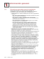
1.2 Safety Guidelines
The safety and reliability of any heat-tracing system
depends on proper design, installation, and
maintenance. Incorrect design, handling,
installation, or maintenance of any of the system
components can cause underheating or overheating
of the pipe, or damage to the heating cable system,
and may result in system failure, electric shock, or
fire. The guidelines and instructions contained in
this guide are important. Follow them carefully to
minimize these risks and to ensure that the SC
system performs reliably.
Pay special attention to the following:
• Important instructions are marked
Important
• Warnings are marked
WARNING
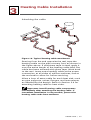
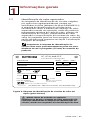
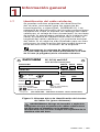
1.3 Typical System
Power
Connection
SC-JBP-S
SC-JBP-L
Splice
SC-JBS-S
SC-JBS-L
End Seal
SC-JBE-S
SC-JBE-L
Above-insulation
Below-insulation
Power
Connection
SC-4, 6, 8, 12PT
Splice
SC-SSC
SC-LSC
End Seal
SC-STC
SC-LTC
Line
sensor
Junction box
(not supplied)
Over limit
sensor
(plastic pipes
only)
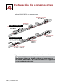
Figure 1: Typical SC heating cable system

nVent.com | 7
1
Important: nVent RAYCHEM SC heating cables
are engineered products. All applications require
design by nVent.
1.4 Electrical Codes
Sections 427 (pipelines and vessels) and 500
(classified locations) of the National Electrical Code
(NEC), and Part 1 of the Canadian Electrical Code,
Sections 18 (hazardous locations) and 62 (Fixed
Electric Space and Surface Heating), govern the
installation of electrical heat-tracing systems.
All heat-tracing-system installations must be in
compliance with these and any other applicable
national or local codes.
1.5 Warranty and Approvals
nVent RAYCHEM SC heating cables and
components are approved for use in hazardous
and nonhazardous locations. Refer to specific
product data sheets for details.
nVent’s limited standard warranty applies to nVent
RAYCHEM SC products. You can access the
complete warranty on nVent.com.
To qualify for an extended 10-year warranty, register
online within 30 days of installation at
nVent.com.
General Information

8 | nVent.com
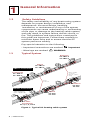
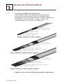
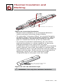
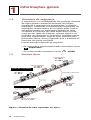
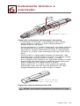
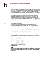
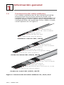
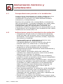
1.6 Heating Cable Construction
nVent RAYCHEM SC heating cables provide
electrical freeze protection and temperature
maintenance for long pipelines. These cables are
available in single, dual, or triple conductor
configurations as shown in Figure 2.
Triple conductor (3SC, 3SC/H, 3SC/F)
Plated copper conductor
Fiberglass braid (pnly for SC, SC/H)
Inner jacket
Conductor Insulation
Tinned-copper braid
Outer jacket
Plated copper conductor
Fiberglass braid (only for SC, SC/H)
Conductor Insulation
Dual conductor (2SC, 2SC/H, 2SC/F)
Inner jacket
Tinned-copper braid
Outer jacket
Plated copper conductor
Fiberglass braid
Inner jacket
Tinned-copper braid
Outer jacket
Single conductor (1SC, 1SC/H)
Figure 2: SC, SC/H, SC/F heating cable construction
General Information
1

nVent.com | 9
1
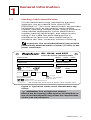
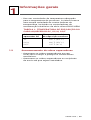
1.7 Heating Cable Identification
Circuit identification tags, required by approval
agencies, can be ordered from nVent (P/N
P000000311). The circuit identification tag provides
information such as the heating cable catalog
number, operating voltage, power output, maximum
cable-sheath temperature, circuit identification
number, heating cable length, and cable current
rating. If the cable has been designed for a
hazardous location, the area classification is
printed in the ‘Haz. Locations’ section of the tag.
Important: The circuit identification tag must be
permanently attached within 3 inches (75 mm) of the
power connection.
CATALOG NO.
CIRCUIT NO. CIRCUIT LENGTH
MAX. SHEATH
TEMP.
USAGE
CODE
W ºC
WATTS VOLTS AMPS
SC, SC/H, and SC/F
Series-Resistance Heating Cable
Baseefa06ATEX0189X
IECEx BAS 06.0049X
(1)
Except 1SC
(SEE OTHER SIDE - VOIR AUSSI AU VERSO - VEJA O OUTRO LADO)
09-IEx-0008X
BR-Ex e II T* (See Observation b)
II 2 GD
Ex e II T* (see schedule)
Ex tD A21 IP66
Hazardous Locations
CLASS DIV GROUP
Ex e ll
-W
Figure 3: Typical SC cable circuit identification tag
(front)
WARNING: Fire or Explosion Hazard.
Ensure the SC heating cable system as identified on
the circuit identification tag meets the requirements
of the area classification.
General Information

10 | nVent.com
1
1.8 General Installation Guidelines
These guidelines are provided to assist the installer
throughout the installation process and should be
reviewed before the installation begins.
• Avoid damage to the SC heating cable as follows:
–Do not use metal pipe straps/banding to secure
cable to pipe.
–Do not install heating cable lengths other
than those listed on the system design
documentation.
–Do not energize before installation is complete.
–Do not cross, group, or overlap cables closely
together. This can cause localized overheating
and a risk of fire or cable failure.
–Keep welding torches clear of cable and protect
against slag falling on cables below.
• Ensure all pipes have been released by the client
for tracing prior to heating cable installation.
• Install cable in a manner that permits removal of
serviceable equipment such as valves, pumps,
and filters, with minimum disruption to the
surrounding heating cable.
• Avoid bending cable to a bend radius less than 1
inch, particularly when installing on valves, pumps,
and other irregularly shaped surfaces. On small
flanges and joints where it is impractical to bend
the cables tightly, metal foil or metal bridging
pieces can be used to fill gaps between the
heating cable and the surface to be heated.
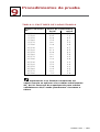
• Ensure heating cable is suitable for the
continuous exposure temperature shown in Table 1.
• Apply thermal insulation as soon as possible after
heat-tracing to prevent mechanical damage to the
heating cables. Waterproof cladding must be
installed immediately after insulation is applied to
prevent the insulation from becoming wet.
• Make all connections to supply cables in above
grade junction boxes and keep covers on junction
boxes when not working on them.
• The minimum installation temperature is –40°F
(–40°C).
General Information

nVent.com | 11
1
• Use a temperature controller suitable for the
process temperature. nVent supplies a wide
range of temperature controllers including the
nVent RAYCHEM series electronic monitoring
controllers.
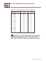
TABLE 1: SC, SC/H, SC/F HEATING CABLE
EXPOSURE TEMPERATURE
SC 400˚F (204˚C)
SC/H
SC/F
480˚F (250˚C)
195˚F (90˚C)
Maximum continuous
exposure temperature
SC heating
cable
1.9 Heating Cable Storage
• Store heating cables in a clean dry location and
protect them from mechanical damage.
• Store heating cables in their shipping container
until they are installed.
General Information

12 | nVent.com
2.1 Check Materials Received
Review the heating cable design documentation
and compare the list of materials to the catalog
numbers of heating cables and components
received to confirm that proper materials are on
site. The heating cable voltage, wattage, and length
for each circuit are printed on the circuit
identification tag.
• Ensure that the heating cable voltage rating is
suitable for the source voltage available.
• Inspect the heating cable and components for
in-transit damage.
• Perform continuity and insulation resistance
testing (minimum 100 MΩ) on each cable as
detailed in Section 9 and record the results on the
Heating Cable Installation Record in Section 12.
• Verify that the conditional sheath temperature
(T-Rating) on the circuit identification tag satisfies
your area requirement and pipe material.
2.2 Check Piping to be Traced
• Make sure all mechanical pipe testing
(i.e. hydrostatic testing/purging) is complete and
the system has been cleared by the client for
tracing.
• Walk the system and plan the routing of the
heating cable on the pipe.
• Verify that the actual pipe length, routes, and
location of pipe fittings such as valves, pipe
supports, hangers, and other components match
the design drawings.
• Inspect the piping and channels for burrs, rough
surfaces, or sharp edges that may damage the
heating cable. Remove if necessary.
• Verify that any surface coatings are dry to the
touch.
2.3 Check Tools
The following tools are needed for installing SC
heat-tracing systems. Additional tools are listed
in the Installation Instructions for each specific
component.
• Proper crimp tool
• Propane or mapp gas torch
• Proper test meters as described in Section 9 of
this manual.
2
Pre-Installation Checks

nVent.com | 13
3
Heating Cable Installation
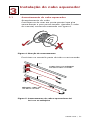
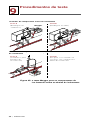
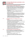
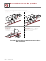
3.1 Heating Cable Payout
Paying out the cable
Make sure to use a reel holder that rotates
smoothly with little tension. Pay out the cable from
the reel as shown in Figure 4.
Figure 4: Payout direction
Position the reels next to the pipe to be traced.
Pipe
Pipe
Single or multiple cables
from one or two reels
Multiple cables
from a single reel
Figure 5: Paying out single and multiple SC heating
cables

14 | nVent.com
3
Heating Cable Installation
Paying out the cable
String the cable along the length of the pipe
following the design. Ensure that the appropriate
amount of heating cable is designated for
component installation, service loops, and pipe
fixtures.
heating cable paying out tips:
• Use a reel holder that pays out smoothly with
little tension. If heating cable snags, stop pulling.
• Pull heating cable by hand. No mechanized
pulling.
• Keep the heating cable strung loosely but close
to the pipe being traced to avoid interference with
supports and equipment.
• Meter marks on the heating cable can be used to
determine heater length.
• Protect all heating cable ends from moisture,
contamination, and mechanical damage.
WARNING: Fire and Shock Hazard. Do not
install damaged cable. Components and cable ends
must be kept dry before and during installation.
when paying out the heating cable, AVOID:
• Sharp edges
• Excessive pulling force or jerking
• Kinking and crushing
• Walking on it, or running over it with equipment
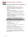
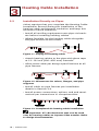
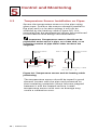
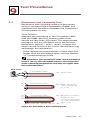
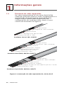
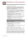
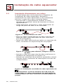
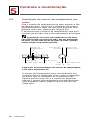
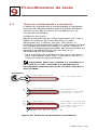
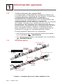
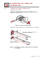
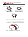
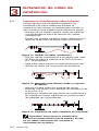
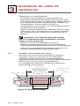
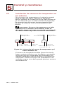
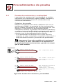
Positioning heating cables
Install cables around the bottom section of pipe,
avoiding bottom dead center (Figure 6).
For two cable runs, install between 30° and 45° on
either side of bottom dead center (Figure 6).
For three cable runs, install bottom cable about 10°
to one side of bottom dead center (Figure 6). On a
vertical pipe, space cables evenly around circum
-
ference of pipe.

nVent.com | 15
3
Heating Cable Installation
Weatherproof
cladding
Insulation
(typ)
Cable ‘A’
Pipe
One heating cable
Three heating cables
Cable ‘C’
Cable ‘B’Cable ‘A’
Cable ‘A’
Two heating cables
Cable ‘B’
Temperature
sensor
Temperature
sensor
Temperature
sensor
Figure 6: SC heating cable positioning (typical cross
section)
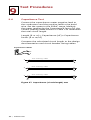
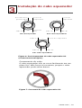
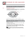
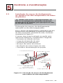
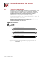
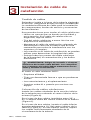
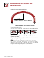
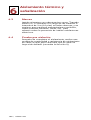
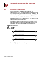
Bending the cable
The heating cable does not bend easily in the flat
plane. Do not force such a bend, as the heating
cable may be damaged.
Figure 7: Bending the SC heating cable

16 | nVent.com
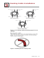
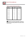
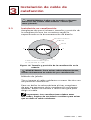
Minimum bend radius
Minimum bend radius 1 inch
1 inch
Figure 8: Minimum bend radius
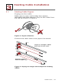
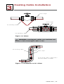
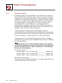
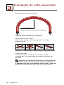
Crossing the cable
Do not cross, overlap, or group the heating cables.
Figure 9: Crossing, overlapping, and grouping
Cutting the cable
Before cutting, confirm that the as-built pipe
matches design specifications.
Important: Any change to designed circuit length
will change power output and design must be
reconfirmed. Do not cut the cable to any length other
than the design length.
3
Heating Cable Installation

nVent.com | 17
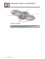
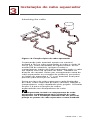
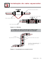
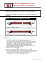
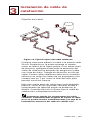
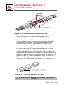
Attaching the cable
Figure 10: Typical heating cable attachment
Starting from the end opposite the reel, tape the
heating cable on the pipe at every foot, as shown in
the figure above. If aluminum tape is used, apply it
over the entire length of the heating cable after the
cable has been secured with glass tape. Work back
to the reel. Leave extra heating cable at the power
connection, at all sides of splices and tees, and at
the end seal to allow for future servicing.
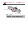
Allow a loop of extra cable for each heat sink, such
as pipe supports, valves, flanges, and instruments,
as detailed by the design. Refer to Section3.4 for
attaching heating cable to heat sinks.
Important: Install heating cable components
immediately after attaching the heating cable. If
immediate installation is not possible, protect the
heating cable ends from moisture.
3
Heating Cable Installation

18 | nVent.com
3
Heating Cable Installation
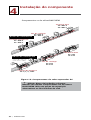
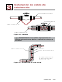
3.2 Installation Directly on Pipes
nVent requires that you complete the Heating Cable
Installation Record during the installation of the
heating cable and thermal insulation and keep this
record for future reference.
• Install all ancillary equipment onto pipe via brack
-
ets before installing heating cables.
• Where feasible, lay the heating cable alongside
the pipe section to be traced.
Figure 11: Paying out heating cable
• Attach heating cables to the pipe with glass tape
at 12–18 inch (300–450 mm) intervals.
• Allow extra cable per design specifications at all
pipe fixtures.
Figure 12: Allowances for valves, flanges, and pipe
supports
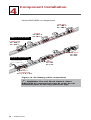
• Install cable on pipe fixtures per installation
details in Section3.4.
• Install power connections, splices, and end termi
-
nations per instructions in component kits.
Figure 13: Completed SC heating cable installation
Important: AT-180 aluminum tape can be used
over SC heating cables to improve heat transfer. Refer
to design documentation.

nVent.com | 19
3
Heating Cable Installation
WARNING: Fire and Shock Hazard. Do not install
damaged cable. It must be replaced.
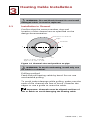
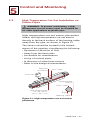
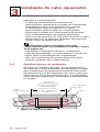
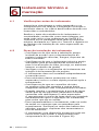
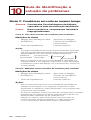
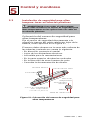
3.3 Installation in Channel
Confirm that the correct number, size and
location of the channel are as specified on the
design documentation.
9 3
Thermal insulation
Pipe
Semicircular channel
Typical: w: 3/4" h: 7/8"
5
Channel
Figure 14: Channel size and position on pipe
WARNING: To avoid overheating, install only one
SC cable in a channel.
Pulling method
Feed and pull heating cable by hand. Do not use
mechanized pulling.
To avoid jacket damage while pulling, make sure the
ends of the channel are free of burrs. Chamfer the
edges or use a guide to route the cable.
Important: Channels must be aligned and free of
dirt or debris to avoid damaging the heating cable.

20 | nVent.com
3
Heating Cable Installation
Splicing and components
• The number of splices and spacing interval
depends on the engineered system design and
reel lengths. The insulation must be opened and
channel interrupted to install the components.
Select and install the components in accordance
with the design documentation provided.
• Use AT-180 Aluminum tape to attach SC heating
cable to the pipe in any areas outside of the chan
-
nel, such as pipe joints.
Important: Buried pipes must use below-
insulation components. See Figure 19 on page<?>.
• Replace the thermal insulation, to the design
thickness, and the waterproof cladding after
component installation.
• Use oversized insulation after installing below-
insulation components.
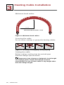
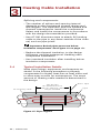
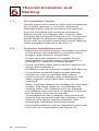
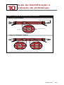
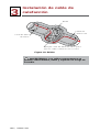
3.4 Typical Installation Details
Wrap pipe fittings, equipment, and supports as
shown in the following examples to properly
compensate for higher heat-loss at heat sinks and
to allow easy access for maintenance. The exact
amount of heating cable needed is determined in
the design.
See design
documentation for
specific heating cable
length needed
SC heating cable
Pipe
Glass tape
Figure 15: Pipe support
A página está carregando...
A página está carregando...
A página está carregando...
A página está carregando...
A página está carregando...
A página está carregando...
A página está carregando...
A página está carregando...
A página está carregando...
A página está carregando...
A página está carregando...
A página está carregando...
A página está carregando...
A página está carregando...
A página está carregando...
A página está carregando...
A página está carregando...
A página está carregando...
A página está carregando...
A página está carregando...
A página está carregando...
A página está carregando...
A página está carregando...
A página está carregando...
A página está carregando...
A página está carregando...
A página está carregando...
A página está carregando...
A página está carregando...
A página está carregando...
A página está carregando...
A página está carregando...
A página está carregando...
A página está carregando...
A página está carregando...
A página está carregando...
A página está carregando...
A página está carregando...
A página está carregando...
A página está carregando...
A página está carregando...
A página está carregando...
A página está carregando...
A página está carregando...
A página está carregando...
A página está carregando...
A página está carregando...
A página está carregando...
A página está carregando...
A página está carregando...
A página está carregando...
A página está carregando...
A página está carregando...
A página está carregando...
A página está carregando...
A página está carregando...
A página está carregando...
A página está carregando...
A página está carregando...
A página está carregando...
A página está carregando...
A página está carregando...
A página está carregando...
A página está carregando...
A página está carregando...
A página está carregando...
A página está carregando...
A página está carregando...
A página está carregando...
A página está carregando...
A página está carregando...
A página está carregando...
A página está carregando...
A página está carregando...
A página está carregando...
A página está carregando...
A página está carregando...
A página está carregando...
A página está carregando...
A página está carregando...
A página está carregando...
A página está carregando...
A página está carregando...
A página está carregando...
A página está carregando...
A página está carregando...
A página está carregando...
A página está carregando...
A página está carregando...
A página está carregando...
A página está carregando...
A página está carregando...
A página está carregando...
A página está carregando...
A página está carregando...
A página está carregando...
A página está carregando...
A página está carregando...
A página está carregando...
A página está carregando...
A página está carregando...
A página está carregando...
A página está carregando...
A página está carregando...
A página está carregando...
A página está carregando...
A página está carregando...
A página está carregando...
A página está carregando...
A página está carregando...
A página está carregando...
A página está carregando...
A página está carregando...
A página está carregando...
A página está carregando...
A página está carregando...
A página está carregando...
A página está carregando...
A página está carregando...
A página está carregando...
A página está carregando...
A página está carregando...
A página está carregando...
A página está carregando...
A página está carregando...
A página está carregando...
A página está carregando...
A página está carregando...
A página está carregando...
A página está carregando...
A página está carregando...
A página está carregando...
A página está carregando...
A página está carregando...
A página está carregando...
A página está carregando...
A página está carregando...
A página está carregando...
A página está carregando...
A página está carregando...
A página está carregando...
A página está carregando...
A página está carregando...
A página está carregando...
A página está carregando...
A página está carregando...
A página está carregando...
A página está carregando...
A página está carregando...
A página está carregando...
A página está carregando...
A página está carregando...
A página está carregando...
A página está carregando...
A página está carregando...
A página está carregando...
-
 1
1
-
 2
2
-
 3
3
-
 4
4
-
 5
5
-
 6
6
-
 7
7
-
 8
8
-
 9
9
-
 10
10
-
 11
11
-
 12
12
-
 13
13
-
 14
14
-
 15
15
-
 16
16
-
 17
17
-
 18
18
-
 19
19
-
 20
20
-
 21
21
-
 22
22
-
 23
23
-
 24
24
-
 25
25
-
 26
26
-
 27
27
-
 28
28
-
 29
29
-
 30
30
-
 31
31
-
 32
32
-
 33
33
-
 34
34
-
 35
35
-
 36
36
-
 37
37
-
 38
38
-
 39
39
-
 40
40
-
 41
41
-
 42
42
-
 43
43
-
 44
44
-
 45
45
-
 46
46
-
 47
47
-
 48
48
-
 49
49
-
 50
50
-
 51
51
-
 52
52
-
 53
53
-
 54
54
-
 55
55
-
 56
56
-
 57
57
-
 58
58
-
 59
59
-
 60
60
-
 61
61
-
 62
62
-
 63
63
-
 64
64
-
 65
65
-
 66
66
-
 67
67
-
 68
68
-
 69
69
-
 70
70
-
 71
71
-
 72
72
-
 73
73
-
 74
74
-
 75
75
-
 76
76
-
 77
77
-
 78
78
-
 79
79
-
 80
80
-
 81
81
-
 82
82
-
 83
83
-
 84
84
-
 85
85
-
 86
86
-
 87
87
-
 88
88
-
 89
89
-
 90
90
-
 91
91
-
 92
92
-
 93
93
-
 94
94
-
 95
95
-
 96
96
-
 97
97
-
 98
98
-
 99
99
-
 100
100
-
 101
101
-
 102
102
-
 103
103
-
 104
104
-
 105
105
-
 106
106
-
 107
107
-
 108
108
-
 109
109
-
 110
110
-
 111
111
-
 112
112
-
 113
113
-
 114
114
-
 115
115
-
 116
116
-
 117
117
-
 118
118
-
 119
119
-
 120
120
-
 121
121
-
 122
122
-
 123
123
-
 124
124
-
 125
125
-
 126
126
-
 127
127
-
 128
128
-
 129
129
-
 130
130
-
 131
131
-
 132
132
-
 133
133
-
 134
134
-
 135
135
-
 136
136
-
 137
137
-
 138
138
-
 139
139
-
 140
140
-
 141
141
-
 142
142
-
 143
143
-
 144
144
-
 145
145
-
 146
146
-
 147
147
-
 148
148
-
 149
149
-
 150
150
-
 151
151
-
 152
152
-
 153
153
-
 154
154
-
 155
155
-
 156
156
-
 157
157
-
 158
158
-
 159
159
-
 160
160
-
 161
161
-
 162
162
-
 163
163
-
 164
164
-
 165
165
-
 166
166
-
 167
167
-
 168
168
-
 169
169
-
 170
170
-
 171
171
-
 172
172
-
 173
173
-
 174
174
-
 175
175
-
 176
176


Raychem Series Resistance Heating Cable Guia de instalação
- Tipo
- Guia de instalação
- Este manual também é adequado para
em outras línguas
Artigos relacionados
Outros documentos
-
Megger MIT400/2 Series Manual do usuário
-
-
-
 nVent RAYCHEM E-100-A High-Profile End Seal Kit Manual do usuário
-
 nVent RAYCHEM RAYSTAT-EX-02 Mechanical Thermostat Guia de instalação
-
koban KCL-01 Manual do usuário
-
Hubbell Wiring Device-Kellems PD2816 Guia de instalação
-
Tyco DigiTrace RAYSTAT-EX-02 Installation Instructions Manual
-
Rointe Erko Manual do proprietário
-
Sime Murelle Equipe 220 660 ErP Manual do proprietário

