
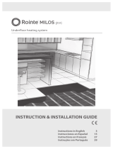
Underoor heating system
BEKIA
INSTRUCTION & INSTALLATION GUIDE
Instructions in English
Instrucciones en Español
Instructions en Français
Instruções em Português
3
15
27
39

2

3
IMPORTANT
Read this manual before attempting to install your BEKIA underoor system. Incorrect installation
could damage the heating wire and will invalidate your warranty.
Contents
1.
Technical information.................................................................................................................................................................4
2.
Recommendations......................................................................................................................................................................5
3.
Floor coverings............................................................................................................................................................................6
4.
Materials needed for installation............................................................................................................................................6
5.
Preparing the suboor................................................................................................................................................................6
6.
Testing the radiant wire.............................................................................................................................................................7
7.
Electrical safety considerations...............................................................................................................................................7
8.
How to modify the radiant wire..............................................................................................................................................8
9.
Installing the radiant wire..........................................................................................................................................................9
10.
Guarantee....................................................................................................................................................................................11
11.
Control card.................................................................................................................................................................................12
12.
Documentation of ownership, installation and electrical connection.............................................................................13
Underoor heating system
BEKIA
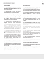
WARNING
The BEKIA underoor system has been designed so that installation is quick and easy, but as
with all electrical systems, certain procedures must be strictly followed. Please ensure that you
have the correct radiant wire(s) for the area you wish to heat. The manufacturer of the radiant wire,
accepts no liability, expressed or implied, for any loss or consequential damage suered as a result
of installations which in any way contravene the instructions that follow.
It is important that before, during and after installation, all requirements are met and understood.
If the instructions are followed, you should have no problems. If you do require help at any stage,
please contact our Technical Support helpline:
T (UK): 0203 321 5929 T (IE): 015 530 526
EN

4
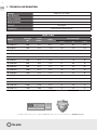
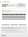
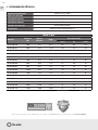
1. TECHNICAL INFORMATION
Voltage 230V AC ±15% 50Hz
Wire thickness 3.6mm
Inner insulation ETFE
Outer insulation PVC
Cold tail 3m length
Certicates CE Declaration of conformity
BEKIA 16 W/m
Model
Wattage
(W)
Lineal
meters
Amps
Resistance (Ω)
(-5%) Ω (+5%)
MSIWBE010 200 12.5 0.87 252 265 278
MSIWBE015 300 18.8 1.30 167 176 185
MSIWBE020 400 25.0 1.74 125 132 139
MSIWBE025 500 31.3 2.17 101 106 111
MSIWBE030 600 37.5 2.61 84 88 92
MSIWBE035 700 43.8 3.04 72 76 80
MSIWBE040 800 50.0 3.48 63 66 70
MSIWBE045 900 56.3 3.91 56 59 62
MSIWBE050 1.000 62.5 4.35 50 53 56
MSIWBE060 1.200 75.0 5.22 42 44 46
MSIWBE070 1.400 87.5 6.09 36 38 40
MSIWBE080 1.600 100.0 6.96 31 33 35
MSIWBE090 1.800 112.5 7.83 28 29 30
MSIWBE100 2.000 125.0 8.70 25 26 27
MSIWBE110 2.400 150.0 10.43 21 22 23
*The BEKIA underfllor heating systems comply with ECODESIGN standards when they are installed with one of ROINTE thermostats.
*
EN

5
EN
2. RECOMMENDATIONS
Recommended Not recommended
It is recommended to read this installation
manual carefully before starting. Consult our
helpline or a competent professional if you are
unsure how to proceed.
It is recommended to ensure the system is
tested before, during and after installation.
It is recommended to plan your wire layout and
installation so that any drilling after tiling (e.g.
for sanitary ware) will not damage the wiring.
It is recommended to maintain a minimum
gap of 80mm between wire runs and from
conductive parts such as water pipes.
It is recommended to check that the wire is
working, immediately before commencing
tiling.
It is recommended to take particular care when
tiling not to dislodge or damage the heating
wire. Ensure that during the course of the
installation that no damage is caused by (but
not limited to) falling objects, sharp objects etc.
It is recommended to ensure the end cap and
manufactured joint are under a full adhesive
bed or levelling compound and covered with a
tile.
It is recommended to ensure that a heat loss
calculation has been carried out and heating
requirements have been met, if you are using
the BEKIA underoor heating system as a
primary source of heating.
It is recommended ensure that the radiant wires
are separated from other heat sources such as
chimneys etc.
It is recommended to ensure that the maximum
thermal resistance of the oor does not exceed
0.15 [m²K / W].
It is recommended to ensure that the control
card at the back of this manual is completed and
xed at the main consumer unit along with any
plans and electrical test records.
It is not recommended to cut or shorten the
radiant wire/heating element at any time.
It is not recommended to commence installation
on a concrete oor that has not been fully cured.
It is not recommended to leave surplus matting
rolled up under units or xtures - USE THE
CORRECT SIZE WIRE.
It is not recommended to install the wire on
irregular surfaces such as stairs or up walls.
It is not recommended to use staples to secure
the radiant wire/heating element to the
suboor.
It is not recommended to run the oor sensor
wire or power lead, over or under the heating
element or close to other heat sources such as
hot water pipes.
It is not recommended to connect two radiant
wires in series, only connect radiant wires in
parallel.
It is not recommended to commence tiling
before testing the wire.
It is not recommended to switch on the installed
wire until 8 days after tting to allow the tile
adhesive to dry completely.
It is not recommended to install the wire in
temperatures less than +5°C.
It is not recommended to bend the radiant wire
under a 25mm radius.
It is not recommended to use the heating system
to dry out levelling compound or adhesive.
It is not recommended to tape over the end cap
or manufactured joint.
It is not recommended to attempt a DIY repair if
you damage the radiant wire/heating element.

6
3. FLOOR COVERINGS
This manual gives instruction for installation of the BEKIA underoor heating system under ceramic,
quarry or natural stone tiles. The maximum thermal resistance of the oor must not exceed 0,15 [m²K / W].
It is possible to install this system under oor nishes such as wood or vinyl, by applying a self
levelling compound over the radiant wire. You must ensure that all heating cables are completely covered
with a minimum of 10mm self levelling compound. It is important that the levelling compound is suitable
for use with underoor heating.
NOTE: Delicate oor nishes such as wood or vinyl have a maximum oor surface temperature of 27°C.
This temperature must NOT be exceeded. Please contact Rointe for further advice if you wish to install the
heating wire under any oor nishes other than ceramic, quarry or natural stone tiles.
4. MATERIALS NEEDED FOR INSTALLATION
Components included in your Rointe BEKIA underoor kit:
• BEKIA radiant wire.
• Installation manual.
Additional components needed as part of your Rointe BEKIA underoor installation:
• A thermostat with oor sensor.
• 30mA Residual Current Device (RCD), required
as part of all installations.
• Digital multi-meter required for testing the
resistance of the wire and oor sensor.
• Electrical housing, back boxes and junction
boxes.
(Back box must be at least 35mm deep)
• Electrical trunking/conduit for housing the
power leads.
• Duct tape (to secure the oor sensor and loose
wires).
• Gloves.
5. SUBFLOOR PREPARATION
Wooden suboors:
• Ensure adequate oor ventilation.
• Existing oorboards need to be securely xed and if necessary pre-levelled with a latex/cement self
levelling compound to give a ush t for the subsequently applied WBP plywood (18mm) or an insulated
tile backer board (10mm).
• A rigid base is essential - xing WBP plywood or Insulation Board to joists will not provide a suitable
oor nish for accepting tiles.
Concrete suboors:
• Ensure you use an extruded polystyrene building or tile backer board (Insulation Board) if installing your
radiant wire onto a cement-based oor.
• Fixing the board should be as per the manufacturer’s instructions.
EN

7
6. TESTING THE HEATING WIRE
The radiant wire must be tested before, during and after tiling. We recommend the use of a digital multimeter
set to a range of 0-2 KΩ for testing. The resistance (Ω) of each wire should be measured. You should carry out
the following tests and should expect the results detailed below:
• Live to neutral should show the resistance value listed in the table on page 4. A ± 5% Ohm reading
tolerance is allowed under manufacturing guidelines. Record the readings on the control card at the
back of the manual.
• Live to earth and neutral to earth should show innity.
NOTE: Due to the high resistance of the heating element, it may not be possible to get a continuity reading
from the wire and as such, continuity testers are not recommended. When checking resistance, make sure
your hands do not touch the meter’s probes as the measurement will include your internal body resistance
and render the measurement inaccurate. If you do not get the expected results, or at any time you believe
there may be a problem, please contact our helpline for guidance.
Floor Sensor
Ensure that the oor sensor is tested before the nal oor nish has been laid. The oor sensor values can
be found in the thermostat instructions. When testing the oor sensor ensure that the meter can read up
to 20kΩ. Rointe thermostats use a 10kΩ oor sensor. The expected resistance is: 10kΩ at 25°C, 12.1kΩ at 20°C,
14.7kΩ at 15°C.
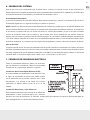
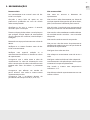
7. ELECTRICAL SAFETY CONSIDERATIONS
All electrical connections must be undertaken by a certied electrician. All work must conform to current
Electrical Regulations. The BEKIA electric underoor
heating system must be controlled via a room
thermostat at all times.
Installing a Residual Current Device (RCD)
The radiant wire must be wired via an 30mA RCD.
A dedicated RCD must be installed if one is not already
present. No more than 7.5kW of heating may be
connected to a single 30mA RCD.
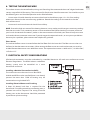
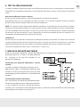
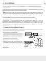
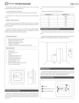
Installing Electrical Boxes and Trunking
A deep (35-40mm) back box is required for the
thermostat. If installing more than two heating mats, a
junction box will be required. The wiring from the
heating wire to the thermostat should be protected
by conduit or plastic trunking.
EN
A
B
D
E
C

8
Connecting the Thermostat
The thermostat should be installed within the room to be heated. In most bathroom installations the
thermostat cannot be located within the bathroom itself as the thermostat could be IP20 rated and must
be located outside of Zone 2. In such cases the thermostat must be tted to the outside of an internal wall
of the bathroom, as close to the installation as possible. Rointe thermostats are rated up to 16A. For larger
installations exceeding 16A multiple thermostats or a suitable contactor will be required. For further advice
contact our helpline.
Once the electrical connections have been made and the system has been tested, the electrician must
complete the control card at the end of this installation manual. This information must be displayed at or
near the consumer unit.
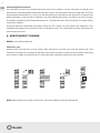
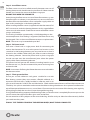
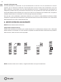
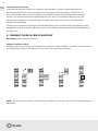
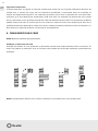
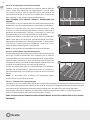
8. HOW TO MODIFY THE WIRE
NEVER cut the heating element.
Check wire size
Double-check that the plan has the proper room dimensions and that you have the correct size. They
shouldn’t run backwards and forwards between walls and obstructions as shown in the examples. Depending
on insulation, airow and overall heat-loss within the room, additional heating may be required.
NOTE: When laying two or more radiant wires, ensure the cold tails reach the thermostat.
EN

9
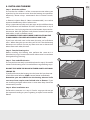
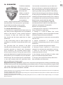
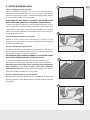
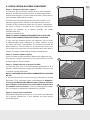
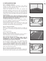
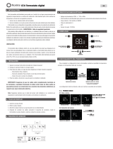
9. INSTALLING THE WIRE
Step 1 - Mark the suboor
Ensure that the suboor is of the same construction where you
intend to lay the wire to ensure that the heating wire performs
eectively. Rointe always recommend that insulation boards,
such
as Rointe Insulation Boards (10mm recommended), are used to
improve the eciency of the radiant wires.
Using a permanent marker, mark out areas on the suboor where
units and xtures will be tted. DO NOT install the wire in any of
these areas. Start by laying the wire in the location closest to the
thermostat. Mark the positions and planned route of the power
lead cables as well as the oor sensor.
ALL MANUFACTURED JOINTS NEED TO BE PLACED ON THE
FLOOR UNDER A FULL BED OF ADHESIVE AND TILES.
If you have awkward areas in the room, the wire can be t these
areas. When doing this ensure that you DO NOT let the heating
element cross or touch. Ensure any loose wires are no closer than
80mm from each other, the wall.
Step 2 - Test the Heating wire
Before installing the heating wire perform the same test as
described on page 7 to ensure that the radiant wire has not been
damaged during planning.
Step 3 - Turn and ax the wire
Ensure you have correctly inserted the thread in step 2. Be careful
not to cut the heating wire. Fix it to the oor using the xing strips.
DO NOT TAPE OVER THE MANUFACTURED JOINTS OR FLOOR
SENSOR TIP.
If you nd that once the heating wire has been laid you have too
much of the wire left over STOP, contact Rointe immediately.
Remember you must NEVER cut the heating element to t
an area or leave surplus mats behind units or xtures. If you
are installing multiple radiant wires in one room they should be
connected in parallel.
Step 4 - After installation test
Perform the same test as in step 2. If at this stage you do not get
the expected reading or you are getting an open circuit contact
Rointe.
EN
1
2
2
2
2
2
4
3

10
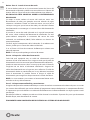
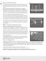
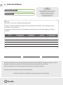
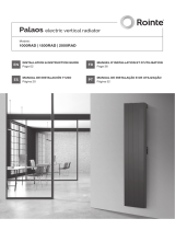
Step 5 - Install oor sensor
The oor sensor must be installed centrally between two runs of
heating element and should extend a mInimum of 150mm into the
heated area. Secure the sensor to the oor using tape.
DO NOT TAPE OVER THE SENSOR TIP.
Avoid placing the oor sensor in areas of heat uctuations e.g. near
hot water pipes or radiators. It may be necessary to cut a channel in
the oor to ensure that the oor sensor and power supply cable are
kept at the same height as the heating element.
When installing the oor sensor (supplied with the thermostat) DO
NOT cross over or under the heating element. At this stage the oor
sensor must also be tested. Check the resistance of the oor sensor
using a multi-meter.
The reading should be approximately 9-23KΩ depending on the
room temperature. If no reading is registered, the oor sensor may
be damaged. If this is the case call Rointe to request a replacement.
NOTE: The sensor may be extended up to 50m.
Step 6 - Fit Power Leads
Each wire is tted with a single power lead for connecting the
wire to the thermostat. To ensure the power lead remains at the
same level as the heating element, you may need to cut or chisel a
channel in the suboor. When doing this take care not to damage
the heating element. Secure the power lead in place using tape
but do not tape over the manufactured joint where the power
supply cable meets the heating element.
The power lead will go into the electrical trunking/conduit up to
the thermostat. It is possible to extend the power lead using twin
and earth cable.
NOTE: Instructions for tting the Rointe thermostat are included in
the thermostat box.
Step 7 - Tile & grout the oor
Ensure you use tile adhesives and grouts suitable for use with
oor heating systems (they must contain a exible additive). It is
important that each tile is solidly bedded in adhesive, with no air
gaps or voids beneath. DO NOT dot and dab the tiles. Check with the manufacturers of the adhesive to ensure
suitability. Use a plastic notched trowel to move the adhesive along the element. Use a piece of cardboard on
top of the exposed element to use as a crawl board. Ensure to test the resistance of the heating wire regularly
during tiling to check the wire hasn’t been damaged during tiling.
If using exible levelling compound before tiling make sure that the wire is completely at, extra tape can be
used to secure the edges of the bre glass mesh to the oor.
Do not store tiles or heavy objects on the wire while tiling. Wait for 8 days to allow the adhesive to dry before
you switch on the system.
FINALLY TEST THE RESISTANCE OF THE HEATING WIRE(S) ONCE TILING IS COMPLETE.
EN
55
6
7

11
10. GUARANTEE
The BEKIA underoor
heating system is
guaranteed by Rointe
to be free from
defects in materials
and workmanship
under normal use and
maintenance, and is
guaranteed to
remain, subject to the limitations and conditions
described below. The heating wire is guaranteed
for 10 YEARS for the oor covering under
which it is tted, except as provided below.
This 10 Years Guarantee applies:
1. only if the unit is registered with Rointe within 30
days after purchase. Registration can be completed
online. In the event of a claim, proof of purchase
is required, so keep your invoice and receipt -
they should state the exact model that has been
purchased;
2. only if the heating wire has been earthed and
protected by a Residual Current Device (RCD) at all
times.
This guarantee does not continue if the oor
covering over the heating wire(s) is damaged, lifted,
replaced, repaired or covered with subsequent
layers of ooring. The guarantee period begins
on the date of purchase. During the period of the
guarantee, Rointe will arrange for the heating wire to
be repaired or (at its discretion) have parts replaced
free of charge. The cost of the repair or replacement
is your only remedy under this guarantee which
does not aect your statutory rights.
Such cost does not extend to any cost other than
direct cost of repair or replacement by Rointe and
does not extend to costs of relaying, replacing or
repairing any oor covering or oor. If the heating
wire fails due to damage caused during installation
or tiling, this guarantee does not apply. It is therefore
important to check that the heating wire is working
(as specied in the installation manual) prior to tiling.
ROINTE SHALL IN NO EVENT BE LIABLE FOR
INCIDENTAL OR CONSEQUENTIAL DAMAGES,
INCLUDING BUT NOT LIMITED TO EXTRA UTILITY
EXPENSES OR DAMAGES TO PROPERTY.
Rointe is not responsible for:
1. Damage or repairs required as a consequence of
faulty installation or application.
2. Damage as a result of oods, res, winds,
lightening, accidents, corrosive atmosphere or other
conditions beyond the control of Rointe.
3. Use of components or accessories not compatible
with this unit.
4. Normal maintenance as described in the
installation and operating manual, such as cleaning
thermostat.
5. Parts not supplied or designated by Rointe.
6. Damage or repairs required as a result of any
improper use, maintenance, operation or servicing.
7. Failure to start due to interruption and/or
inadequate electrical service.
8. Any damage caused by frozen or broken water
pipes in the event of equipment failure.
9. Changes in the appearance of the product that
does not aect its performance.
Replacement Warranty Guidelines: If you make a mistake and damage the new heating wire before laying
the oor covering, return the damaged heating wire to Rointe within in 30 days along with your original dated
sales receipt. Rointe WILL REPLACE ANY PRETILED RADIANT WIRE (MAXIMUM 1) WITH ANOTHER RADIANT
WIRE OF THE SAME MAKE AND MODEL FOR FREE.
(i) Repaired radiant wires carry a 5 year guarantee only. Under no circumstances is Rointe responsible for the repair or replacement of any tiles / oor covering which may
be removed or damaged in order to aect the repair.
(ii) The Replacement Guarantee does not cover any other type of damage, misuse or improper installation due to improper adhesive or suboor conditions. Limit of one free
replacement heating wire per customer or installer.
(iii) Damage to the heating wire that occurs after tiling, such as lifting a damaged tile once it has set, or suboor movement causing oor damage, is not covered by the
Replacement Guarantee.
EN

12
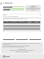
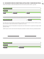
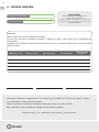
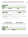
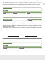
11. CONTROL CARD
Date Signed Name or company stamp
Attention:
Do not cut or shorten the heating element.
Ensure that the entire heating elements, including the joints, are installed under the tiles in the installation.
The heating element must be used in conjunction with a 30mA RCD.
Model Resistance before Resistance after
Insulation
resistance pass
Floor sensor
resistance
CAUTION
Electric uneroor heating systems.
Risk of electric shock.
Electric wiring and heating panels contained below
the oor. Do not penetrate with nails, screws, or similar
devices. Do not restrict the thermal emission of the
heated oor.
This form must be completed as part of the Rointe Guarantee. Ensure that the values are as per the
instruction manual.
This card must be situated close to the consumer unit in a visible place.
Note: Draw a plan showing the layout of the heating wire.
Rointe UK & Ireland
T (UK): 0203 321 5929 | T (IE): 015 530 526 | E: support@rointe.co.uk
www.rointe.co.uk | www.rointe.ie
Heating wire location
Total wattage
EN

13
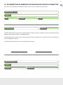
12.
DOCUMENTATION OF OWNERSHIP, INSTALLATION AND ELECTRICAL CONNECTION
This form must be lled out completely, otherwise you may invalidate your guarantee.
I hereby conrm that I have read & understood the contents of this installation manual and that the all the
elements have been installed as specied therein.
I acknowledge that no claim can be brought against the manufacturer or its agents for any consequential
loss or damage whatsoever.
I conrm that the heating wire(s) was working prior to tiling.
Owner’s name
Electrician’s name
Installer’s name
Address
Address
P.C.
Telephone
Telephone
License nº
Telephone
Email
Installer’s signature Date
EN

14

15
IMPORTANTE
Lea cuidadosamente este manual antes de instalar el hilo radiante. Una instalación incorrecta podría
dañarlo e invalidará la garantía.
Contenido
1.
Información técnica ..................................................................................................................................................................16
2.
Recomendaciones.....................................................................................................................................................................17
3.
Revestimientos para suelo.......................................................................................................................................................18
4.
Materiales necesarios................................................................................................................................................................18
5.
Preparación del subsuelo.........................................................................................................................................................18
6.
Pruebas al sistema......................................................................................................................................................................19
7.
Consejos de seguridad eléctrica............................................................................................................................................19
8. Modicación del hilo radiante.........................................................................................................................................20
9. Instalación del hilo..............................................................................................................................................................21
10.
Garantía.......................................................................................................................................................................................23
11.
Tarjeta de control.......................................................................................................................................................................24
12.
Documentación del propietario............................................................................................................................................25
Sistema de calefacción por suelo radiante
BEKIA
ATENCIÓN
El fabricante del hilo radiante no acepta responsabilidad alguna, expresa ni implícita, por cualquier
pérdida o daño derivado sufrido a raíz de instalaciones que de cualquier forma contravengan lo
expuesto en las siguientes instrucciones.
Si se siguen estas instrucciones, no tendrán ningún tipo de problema. Sin embargo, si necestia ayuda
llame a nuestra línea de asistencia:
902 130 134
ES

16
1. INFORMACIÓN TÉCNICA
Tensión nominal 230V AC ±15% 50Hz
Espesor del hilo 3,6mm
Aislamiento interno ETFE
Aislamiento externo PVC
Cola fría (Cold tail) 3m de longitud
Aprobaciones Declaración de conformidad CE
BEKIA 16 W/m
Referencia
Potencia
(W)
Metros
lineales
Amps
Resistencia (Ω)
(-5%) Ω (+5%)
MSNWBE010 200 12,5 0,87 252 265 278
MSNWBE015 300 18,8 1,30 167 176 185
MSNWBE020 400 25,0 1,74 125 132 139
MSNWBE025 500 31,3 2,17 101 106 111
MSNWBE030 600 37,5 2,61 84 88 92
MSNWBE035 700 43,8 3,04 72 76 80
MSNWBE040 800 50,0 3,48 63 66 70
MSNWBE045 900 56,3 3,91 56 59 62
MSNWBE050 1.000 62,5 4,35 50 53 56
MSNWBE060 1.200 75,0 5,22 42 44 46
MSNWBE070 1.400 87,5 6,09 36 38 40
MSNWBE080 1.600 100,0 6,96 31 33 35
MSNWBE090 1.800 112,5 7,83 28 29 30
MSNWBE100 2.000 125,0 8,70 25 26 27
MSNWBE110 2.400 150,0 10,43 21 22 23
*Los sistemas de suelo radiante Rointe cumplen con la normativa de ECODISEÑO siempre que sean instalados con los termostatos ROINTE.
*
ES

17
2. RECOMENDACIONES
Se recomienda No se recomienda
Se recomienda leer atentamente este manual
de instalación antes de comenzar. Consultar
con nuestra línea de soporte técnico o con un
profesional competente si no está seguro de
cómo continuar.
Se recomienda probar el sistema antes, durante
y después de la instalación.
Se recomienda planicar el trazado e instalación
del hilo radiante para que cualquier perforación
después del revestimiento (por ejemplo, para la
jación de sanitarios) no dañe el cableado.
Se recomienda mantener un espacio mínimo de
80 mm entre el cableado.
Se recomienda asegurar que el sistema funciona
antes de iniciar el revestimiento.
Se recomienda vericar cuidadosamente si el
revestimiento no desplaza o daña los cables de
calefacción.
Se recomienda asegurar que la unión entre el
cable de calefacción y el cable de alimentación,
así como el terminal del cable están cubiertos
con cemento exible antes de colocar el suelo
nal.
Se recomienda asegurar que el cálculo de
pérdida de calor se ha llevado a cabo y las
necesidades de calefacción se han cumplido,
si está utilizando el sistema de calefacción por
suelo radiante como una fuente primaria de
calefacción.
Se recomienda asegurar de que los hilos
radiantes se separan de otras fuentes de calor,
tales como luminarias y chimeneas.
Se recomienda asegurar que la tarjeta de
control en la parte posterior del manual sea
completada y jada a la unidad de consumo
principal, junto con los planos y los registros de
pruebas eléctricas.
No se recomienda cortar ni acortar el elemento
de calefacción en ningún momento.
No se recomienda instalar el hilo radiante
directamente debajo de cualquier suelo que
no sea de cerámica, piedra, mármol o piedra
natural.
No se recomienda comenzar la instalación en un
suelo de hormigón que no se haya curado por
completo.
No se recomienda dejar el excedente de hilo
enrollado bajo unidades o uniones - utilice el
tamaño correcto.
No se recomienda instalar el hilo de suelo
radiante en escaleras en paredes.
No se recomienda utilizar grapas para jar el
elemento de calefacción al subsuelo.
No se recomienda colocar el cable del sensor
de suelo o cable de alimentación encima o
debajo del elemento de calefacción o cerca de
otras fuentes de calor como tuberías de agua
caliente.
No se recomienda conectar dos hilos en serie:
conecte sólo hilos en paralelo.
No se recomienda comenzar a colocar el suelo
antes de probar el hilo.
No se recomienda encender el hilo instalado
antes de que transcurran ocho días desde la
instalación para permitir que el adhesivo para
baldosas se seque por completo.
No se recomienda instalar el hilo a temperaturas
inferiores de +5°C.
No se recomienda doblar el cable de calefacción
debajo de 25mm de radio.
No se recomienda utilizar el sistema de
calefacción para secar el compuesto de
nivelación o adhesivo.
ES

18
3. REVESTIMIENTOS PARA SUELO
Este manual proporciona instrucciones para la instalación del hilo radiante Rointe bajo cerámica o baldosas
de piedra natural. La resistencia térmica máxima del suelo no debe exceder 0,15 [m²K/W]. Es posible instalar
el sistema bajo suelos como madera o vinilo mediante la aplicación de un compuesto autonivelante sobre el
hilo radiante. Debe asegurarse de que el hilo y cable quedan completamente cubiertos con un mínimo de 10
mm de compuesto autonivelante. Es importante que el compuesto autonivelante sea adecuado para su uso
con calefacción por suelo radiante.
NOTA: suelos de madera o vinilo tienen una temperatura de supercie de suelo máxima de 27°C. Esta
temperatura NO debe ser excedida. Por favor, póngase en contacto con Rointe para más información si desea
instalar el hilo radiante bajo cualquier otro suelo diferente a cerámica o baldosas de piedra natural.
4. MATERIALES NECESARIOS
Componentes que incluye su kit de hilo radiante:
• Hilo radiante eléctrico Rointe.
• Manual de instalación.
Componentes que NO incluye su kit de hilo radiante:
• Termostato con sensor de suelo Rointe.
• Interruptor diferencial de 30mA, necesario en
todas las instalaciones.
• Multímetro, necesario para probar la resistencia
• Caja eléctrica, caja para el termostato y caja de
conexiones (La caja para el termostato debe
tener al menos 35mm. de profundidad).
• Cinta adhesiva (para jar el sensor de suelo y los
cables sueltos).
• Guantes
5. PREPARACIÓN DEL SUBSUELO
Subsuelos de madera:
• Asegurar una ventilación adecuada.
• El suelo existente debe estar estable y seguro, y si es necesario nivelado cn un compuesto de látex/
cemento autonivelante para quedar preaparado y ajustado para la aplicación posterior de la placa de
aislamiento.
Subsuelos de hormigón:
• Asegúrese de que se utiliza poliestileno extruido para construcción o placas de aislamiento al instalar el
sistema en una base de cemento.
• La jación de las placas debe ser realizada de acuerdo con las instruciones del fabricante.
ES

19
6. PRUEBAS DEL SISTEMA
Uno de los pasos más importantes que se deben llevar a cabo a la hora de instalar el hilo radiante es el
proceso de prueba. Asegúrese siempre de que ha probado el hilo radiante ANTES, DURANTE y DESPUÉS de la
instalación utilizando un multímetro y un enchufe con conexión a tierra.
Procedimiento de pruebas
La resistencia (ohmios) de cada hilo radiante debe medirse entre fase y neutro. Se recomienda el uso de un
multímetro digital con un rango de 0 a 2kΩ para realizar las pruebas.
NOTA: debido a la elevada resistencia del elemento de calefacción, puede que no sea posible obtener una
lectura continua del hilo y, por lo tanto, no se recomiendan dispositivos de medición continua. Al comprobar
la resistencia, asegúrese de que sus manos no tocan las sondas del medidor, ya que si lo hace la medida
incluirá la resistencia interna de su cuerpo y, por lo tanto, hará que la medida no sea precisa. Anote las
lecturas de la resistencia y compare con la tabla de la página 16. Los valores medidos deben estar dentro del
±5% de los valores indicados en la tabla. Si en cualquier momento las lecturas no se encuentran dentro de las
directrices anteriores, o si sospecha que hay algún tipo de problema, llame a la línea de asistencia de Rointe.
Sensor de suelo
Asegúrese que el sensor de suelo sea probado antes de que el suelo nal sea colocado. Los valores del sensor
de suelo se pueden encontrar en el manual de instrucciones del termostato. Cuando este probando el sensor
de suelo asegúrese de que el medidor puede leer hasta 20kΩ. Los termostatos Rointe utilizan un sensor de
suelo de 10kΩ. La resistencia esperada es: 10kΩ a 25ºC, 12,1kΩ a 20°C, 14,7kΩ a 15ºC.
7. CONSEJOS DE SEGURIDAD ELÉCTRICA
Todas las conexiones eléctricas deben ser realizadas
por un electricista cualicado. Todo el trabajo debe
cumplir con las regulaciones eléctricas vigentes.
Instalación de un interruptor diferencial (ID)
El sistema debe estar conectado a través de un ID. Si en
el lugar de instalación no existe uno, debe instalar
un ID dedicado. No se pueden conectar más 7,5KW
de potencia a un mismo ID de 30mA. Para cargas
superiores se deben utilizar varios ID o un ID de
100mA.
Instalación de enlaces y cajas eléctricas
Para el termostato necesitará una caja de 35-40mm de
profundidad. Si está instalando dos o más sistemas,
ecesitará una caja de conexiones. El cable de alimentación que conecta el sistema al termostato debe ser
estar protegido con un conducto o tubo de plástico.
ES
A
B
D
E
C

20
Conexión del termostato
El termostato debe ser conectado a la red de alimentación a través de un ID, de acuerdo con las normas
vigentes, por un electricista calicado. El termostato debe instalarse dentro de la habitación o área que
desea calefactar; sin embargo, en el caso de instalaciones en baños, se recomienda que el termostato se
coloque en el exterior de una pared interna del baño, lo más cerca posible del sistema de suelo radiante. Los
termostatos Rointe están diseñados para cargas hasta 16A. Para instalaciones que excedan 16A, se requieren
múltiples termostatos o un contactor. Para más consejos contacte con Rointe.
Una vez que se han realizado las conexiones eléctricas y el sistema ha sido probado, el electricista debe
completar la tarjeta de control ubicada en la parte posterior de este manual de instalación. Esta información
debe disponerse cerca de la unidad de consumo.
8. MODIFICACIÓN DEL HILO RADIANTE
NUNCA corte el elemento de calefacción.
Compruebe el tamaño del hilo
Tómese unos minutos para vericar que su plano dispone de las dimensiones correctas de la habitación
donde realizará la instalación. Los hilos radiantes no pueden ser colocados detrás o delante, entre paredes u
obstrucciones, como se muestra en los ejemplos.
NOTA: cuando use dos o más sistemas, asegúrese de colocar una caja de conexiones.
ES
A página está carregando...
A página está carregando...
A página está carregando...
A página está carregando...
A página está carregando...
A página está carregando...
A página está carregando...
A página está carregando...
A página está carregando...
A página está carregando...
A página está carregando...
A página está carregando...
A página está carregando...
A página está carregando...
A página está carregando...
A página está carregando...
A página está carregando...
A página está carregando...
A página está carregando...
A página está carregando...
A página está carregando...
A página está carregando...
A página está carregando...
A página está carregando...
A página está carregando...
A página está carregando...
A página está carregando...
A página está carregando...
A página está carregando...
A página está carregando...
A página está carregando...
A página está carregando...
-
 1
1
-
 2
2
-
 3
3
-
 4
4
-
 5
5
-
 6
6
-
 7
7
-
 8
8
-
 9
9
-
 10
10
-
 11
11
-
 12
12
-
 13
13
-
 14
14
-
 15
15
-
 16
16
-
 17
17
-
 18
18
-
 19
19
-
 20
20
-
 21
21
-
 22
22
-
 23
23
-
 24
24
-
 25
25
-
 26
26
-
 27
27
-
 28
28
-
 29
29
-
 30
30
-
 31
31
-
 32
32
-
 33
33
-
 34
34
-
 35
35
-
 36
36
-
 37
37
-
 38
38
-
 39
39
-
 40
40
-
 41
41
-
 42
42
-
 43
43
-
 44
44
-
 45
45
-
 46
46
-
 47
47
-
 48
48
-
 49
49
-
 50
50
-
 51
51
-
 52
52


Rointe Bekia Manual do proprietário
- Tipo
- Manual do proprietário
- Este manual também é adequado para
em outras línguas
- español: Rointe Bekia El manual del propietario
- français: Rointe Bekia Le manuel du propriétaire
- English: Rointe Bekia Owner's manual
Artigos relacionados
-
 Rointe Milos Manual do proprietário
-
 Rointe Atria Manual do proprietário
-
 Rointe ST.0 analogue thermostat Manual do proprietário
-
Rointe Erko Manual do proprietário
-
Rointe CT.2 Manual do proprietário
-
-
 Rointe CT.0 Manual do proprietário
-
 Rointe Palaos radiador elétrico vertical digital 2022 Manual do proprietário
-
 Rointe ST. 2 Manual do proprietário


