Hisense R32 Air Conditioner Manual do usuário
- Categoria
- Condicionadores de ar de sistema split
- Tipo
- Manual do usuário

Thank you very much for purchasing this Air Conditioner. Please
read this use and installation instructions carefully before installing
and using this appliance and keep this manual for future reference.
ENGLISH 意大利文 ESPAÑOL PORTUGUÊS
ITALIANO

Contents
3
1
13
14
15
16
17
17
13
Safety instructions
Preparation before use
Safety Precautions
Installation instructions
Installation diagram
Select the installation locations
Connecting of the cable
Wiring diagram
Outdoor unit installation
Air purging
4

1
Safety instructions
1. To guarantee the unit work normally, please read the manual carefully before
installation, and try to install strictly according to this manual.
2. Do not let air enter the refrigeration system or discharge refrigerant when moving the
air conditioner.
6. After installing, the consumer must operate the air conditioner correctly
according to this manual, keep a suitable storage for maintenance and moving of
the air conditioner in the future.
5. There must be an air-break switch.
4. Check the connecting cables and pipes carefully, make sure they are correct and firm
before connecting the power of the air conditioner.
7. Fuse of indoor unit: T 3.15A 250VAC or T 5A 250VAC. Please refer to the screen
printing on the circuit board for the actual parameters, which must be consistent with the
parameters on the screen printing.
8. For 7k 12k models, f T 15A 250VAC or T 20A 250VAC.
refer to the screen printing on the circuit board for the actual parameters, which must be
consistent with the parameters on the screen printing.
~ use of outdoor unit: Please
3. Properly ground the air conditioner into the earth.
10. For 24k models, f T 30A 250VAC . use of outdoor unit:
12. Warning: Risk of electric shock can cause injury or death: Disconnect all
remote electric power supplies before servicing .
11. The installation instructions for appliances that are intended to be permanently
connected to fixed wiring, and have a leakage current that may exceed 10 mA,
shall state that the installation of a residual current device (RCD) having a rated
residual operating current not exceeding 30 mA is advisable.
13. The maximum length of the connecting pipe between the indoor unit and
outdoor unit should be less than 5 meters. It will affect the efficiency of the air
conditioner if the distance longer than that length.
15. This appliance can be used by children aged from 8 years and above and
persons with reduced physical, sensory or mental capabilities or lack of experience
and knowledge if they have been given supervision or instruction concerning use
of the appliance in a safe way and understand the hazards involved. Children shall
not play with the appliance. Cleaning and user maintenance shall not be made by
children without supervision.
16.The batteries in remote controller must be recycled or disposed of properly.
Disposal of Scrap Batteries --- Please discard the batteries as sorted municipal
waste at the accessible collection point.
9. For models, f 20A 250VAC. 18k use of outdoor unit: T
14. This appliance is not intended for use by persons (including children) with
reduced physical, sensory or mental capabilities, or lack of experience and
knowledge, unless they have been given supervision or instruction concerning use
of the appliance by a person responsible for their safety.Children should be
supervised to ensure that they do not play with the appliance.

2
Safety instructions
21. The appliance shall not be installed in the laundry.
19. The appliance shall be installed in accordance with national wiring regulations.
20. The air conditioner must be installed by professional or qualified persons.
18. If the supply cord is damaged, it must be replaced by the manufacturer, its
service agent or similarly qualified persons in order to avoid a hazard.
22. Regarding to installation, please refer to section “Installation instructions”.
23. Regarding to maintenance, please refer to section “Maintenance”.
24. For models using R32 refrigerant, piping connection should be conducted on
outdoor side.
17. If the appliance is fixed wiring, the appliance must be fitted with means for
disconnection from the supply mains having a contact separation in all poles that
provide full disconnection under over voltage category III conditions, and these
means must be incorporated in the fixed wiring in accordance with the wiring rules.

3
Preparation before use
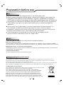
The air conditioner has an Auto-Restart function.
Each time after the remote control is replaced with new batteries or is energized, auto presetting
heat pump.If the air conditioner you purchased is a Cooling Only one, heat pump remote controller can also be used.
remote control
Remote Control presetting
Before using the air conditioner, be sure to check and preset the following.
Auto Restart Presetting
Hold down any button on remote control to activate the back light. It automatically shuts off 10 seconds later.
Note: Back-light is an optional function.
Back-light function (optional) of Remote Control
This appliance is made of recyclable or re-usable material. Scrapping must be carried out in
compliance with local waste disposal regulations. Before scrapping it, make sure to cut off the
mains cord so that the appliance cannot be re-used.
For more detailed information on handling and recycling this product, contact your local authorities
who deal with the separate collection of rubbish or the shop where you bought the appliance.
SCRAPPING OF APPLIANCE
This appliance is marked according to the European Directive 2012/19/EC,
Waste Electrical and Electronic Equipment (WEEE).
This marking indicates that this product should not be disposed
with other household wastes throughout the EU. To prevent possible
harm to the environment or human health from uncontrolled waste
disposal,recycle it responsibly to promote the sustainable reuse of
material resources. To return your used device, please use the return
and collection systems or contact the retailer where the product was
purchased. They can take this product for environmental safe recycling.
Note
Preset
Safeguarding the environment
When charging refrigerant into the system, make sure to charge in liquid state,if the
refrigerant of the appliance is R32.Otherwise, chemical composition of refrigerant
(R32) inside the system may change and thus affect performance of the air conditioner.
According to the character of
of the tube is very high, so be sure to be careful when you install and repair the
appliance.
refrigerant (R32,the value of GWP is 675), the pressure
If the supply cord is damaged, it must be replaced by the manufacturer, its
service agent or similarly qualified persons in order to avoid a hazard.
Installation of this product must be done by experienced service technicians
professional installers only in accordance with this manual.
The temperature of refrigerant circuit will be high, please keep the
interconnection cable away from the copper tube.
For the multi system, the refrigerant refer to the multi outdoor unit.

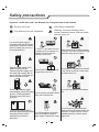
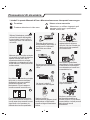
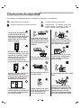
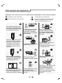
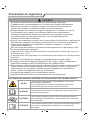
Safety precautions
Symbols in this Use and Care Manual are interpreted as shown below.
Be sure not to do.
Pay attention to such a situation.
Grounding is essential.
Warning: Incorrect handling could
cause a serious hazard, such as death,
serious injury, etc.
4
Do not use the power supply
circuit breaker or pull off the plug
to turn it off during operation.
This may cause a fire due to
spark, etc.
Keep the power supply circuit
breaker or plug from dirt.
Connect the power supply cord
to it firmly and correctly, lest an
electric shock or a fire break out
due to insufficient contact.
Use correct power supply in
accordance with the rating plate
requirement. Otherwise, serious
faults or hazard may occur or a
fire maybe break out.
Do not knit, pull or press the power
supply cord, lest the power supply cord
be broken. An electric shock or fire is
probably caused by a broken power
supply cord.
Never insert a stick or similar obstacle
to the unit. Since the fan rotates at high
speed, this may cause an injury.
Do not repair the appliance by yourself.
If this is done incorrectly, it may cause
an electric shock, etc.
Turn off the appliance by remote
control firstly before cutting off
power supply if malfunction occurs.
It is harmful to your health if the cool
air reaches you for a long time. It is
advisable to let the air flow be
deflected to all the room.
Prevent the air flow from reaching
the gas burners and stove.
Do not touch the operation buttons
when your hands are wet.
Do not put any objects on the outdoor
unit.
It is the user's responsibility to
make the appliance be grounded
according to local codes or
ordinances by a licenced
technician.
OFF
OFF
ON
ON
ON
OFF
MODE
SMART
QUIET DIM MER
ECONOM Y
FEEL
FAN SPEED
CLOCK
TIMER ON
TIMER OFF
SLEEP
TEMP.
TEMP.
SUPER

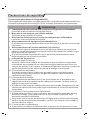
Safety precautions
Precautions for using R32 refrigerant
5
The basic installation work procedures are the same as the conventional refrigerant
(R22 or R410A). However, pay attention to the following points:
CAUTION
1. Transport of equipment containing flammable refrigerants
Compliance with the transport regulations
2. Marking of equipment using signs
Compliance with local regulations
3. Disposal of equipment using flammable refrigerants
Compliance with national regulations
4. Storage of equipment/appliances
The storage of equipment should be in accordance with the manufacturer's
instructions.
5. Storage of packed (unsold) equipment
Storage package protection should be constructed such that mechanical
damage to the equipment inside the package will not cause a leak of the
refrigerant charge.
The maximum number of pieces of equipment permitted to be stored together
will be determined by local regulations.
6. Information on servicing
6-1 Checks to the area
Prior to beginning work on systems containing flammable refrigerants, safety
checks are necessary to ensure that the risk of ignition is minimised. For repair
to the refrigerating system, the following precautions shall be complied with
prior to conducting work on the system.
6-2 Work procedure
Work shall be undertaken under a controlled procedure so as to minimise the
risk of flammable gas or vapour being present while the work is being
performed.
6-3 General work area
All maintenance staff and others working in the local area shall be instructed
on the nature of work being carried out. Work in confined spaces shall be
avoided.
The area around the workspace shall be sectioned off. Ensure that the
conditions within the area have been made safe by control of flammable
material.
6-4 Checking for presence of refrigerant
The area shall be checked with an appropriate refrigerant detector prior to and
during work, to ensure the technician is aware of potentially flammable
atmospheres.
Ensure that the leak detection equipment being used is suitable for use with
flammable refrigerants, i.e. non-sparking, adequately sealed or intrinsically
safe.

Safety precautions
6
CAUTION
6-5 Presence of fire extinguisher
If any hot work is to be conducted on the refrigeration equipment or any
associated parts, appropriate fire extinguishing equipment shall be available
to hand.
Have a dry powder or CO2 fire extinguisher adjacent to the charging area.
6-6 No ignition sources
No person carrying out work in relation to a refrigeration system which involves
exposing any pipe work that contains or has contained flammable refrigerant
shall use any sources of ignition in such a manner that it may lead to the risk of
fire or explosion.
All possible ignition sources, including cigarette smoking, should be kept
sufficiently far away from the site of installation, repairing, removing and
disposal, during which flammable refrigerant can possibly be released to the
surrounding space.
Prior to work taking place, the area around the equipment is to be surveyed to
make sure that there are no flammable hazards or ignition risks. “No Smoking”
signs shall be displayed.
6-7 Ventilated area
Ensure that the area is in the open or that it is adequately ventilated before
breaking into the system or conducting any hot work.
A degree of ventilation shall continue during the period that the work is carried
out.
The ventilation should safely disperse any released refrigerant and preferably
expel it externally into the atmosphere.
6-8 Checks to the refrigeration equipment
Where electrical components are being changed, they shall be fit for the
purpose and to the correct specification.
At all times the manufacturer's maintenance and service guidelines shall be
followed. If in doubt consult the manufacturer's technical department for
assistance.
The following checks shall be applied to installations using flammable
refrigerants:
– The charge size is in accordance with the room size within which the
refrigerant containing parts are installed;
– The ventilation machinery and outlets are operating adequately and are not
obstructed;
– If an indirect refrigerating circuit is being used, the secondary circuit shall be
checked for the presence of refrigerant;
– Marking to the equipment continues to be visible and legible. Markings and
signs that are illegible shall be corrected;
– Refrigeration pipe or components are installed in a position where they are
unlikely to be exposed to any substance which may corrode refrigerant
containing components, unless the components are constructed of materials

Safety precautions
7
CAUTION
which are inherently resistant to being corroded or are suitably protected
against being so corroded.
6-9 Checks to electrical devices
Repair and maintenance to electrical components shall include initial safety
checks and component inspection procedures.
If a fault exists that could compromise safety, then no electrical supply shall be
connected to the circuit until it is satisfactorily dealt with.
If the fault cannot be corrected immediately but it is necessary to continue
operation, an adequate temporary solution shall be used.
This shall be reported to the owner of the equipment so all parties are advised.
Initial safety checks shall include:
– That capacitors are discharged: this shall be done in a safe manner to avoid
possibility of sparking;
– That there no live electrical components and wiring are exposed while
charging, recovering or purging the system;
– That there is continuity of earth bonding.
7. Repairs to sealed components
During repairs to sealed components, all electrical supplies shall be
disconnected from the equipment being worked upon prior to any removal of
sealed covers, etc.
If it is absolutely necessary to have an electrical supply to equipment during
servicing, then a permanently operating form of leak detection shall be located
at the most critical point to warn of a potentially hazardous situation.
Particular attention shall be paid to the following to ensure that by working on
electrical components, the casing is not altered in such a way that the level of
protection is affected.
This shall include damage to cables, excessive number of connections,
terminals not made to original specification, damage to seals, incorrect fitting
of glands, etc.
Ensure that apparatus is mounted securely.
Ensure that seals or sealing materials have not degraded such that they no
longer serve the purpose of preventing the ingress of flammable atmospheres.
Replacement parts shall be in accordance with the manufacturer's
specifications.
NOTE:
The use of silicon sealant may inhibit the effectiveness of some types of
leak detection equipment. Intrinsically safe components do not have to be
isolated prior to working on them.
8. Repair to intrinsically safe components
Do not apply any permanent inductive or capacitance loads to the circuit
without ensuring that this will not exceed the permissible voltage and current
permitted for the equipment in use.
Intrinsically safe components are the only types that can be worked on while

Safety precautions
8
CAUTION
live in the presence of a flammable atmosphere. The test apparatus shall be at
the correct rating.
Replace components only with parts specified by the manufacturer.
Other parts may result in the ignition of refrigerant in the atmosphere from a
leak.
9. Cabling
Check that cabling will not be subject to wear, corrosion, excessive pressure,
vibration, sharp edges or any other adverse environmental effects.
The check shall also take into account the effects of aging or continual
vibration from sources such as compressors or fans.
10.Detection of flammable refrigerants
Under no circumstances shall potential sources of ignition be used in the
searching for or detection of refrigerant leaks.
A halide torch (or any other detector using a naked flame) shall not be used.
11.Leak detection methods
The following leak detection methods are deemed acceptable for systems
containing flammable refrigerants:
– Electronic leak detectors shall be used to detect flammable refrigerants, but
the sensitivity may not be adequate, or may need re-calibration. (Detection
equipment shall be calibrated in a refrigerant-free area.)
– Ensure that the detector is not a potential source of ignition and is suitable
for the refrigerant used.
– Leak detection equipment shall be set at a percentage of the LFL of the
refrigerant and shall be calibrated to the refrigerant employed and the
appropriate percentage of gas (25 % maximum) is confirmed.
– Leak detection fluids are suitable for use with most refrigerants but the use
of detergents containing chlorine shall be avoided as the chlorine may react
with the refrigerant and corrode the copper pipe-work.
– If a leak is suspected, all naked flames shall be removed/ extinguished.
– If a leakage of refrigerant is found which requires brazing, all of the
refrigerant shall be recovered from the system, or isolated (by means of shut
off valves) in a part of the system remote from the leak.
– Oxygen free nitrogen (OFN) shall then be purged through the system both
before and during the brazing process.
12.Removal and evacuation
When breaking into the refrigerant circuit to make repairs – or for any other
purpose – conventional procedures shall be used.
However, it is important that best practice is followed since flammability is a
consideration.
The following procedure shall be adhered to:
– Remove refrigerant;
– Purge the circuit with inert gas;

Safety precautions
9
CAUTION
– Evacuate;
– Purge again with inert gas;
– Open the circuit by cutting or brazing.
The refrigerant charge shall be recovered into the correct recovery cylinders.
The system shall be “flushed” with OFN to render the unit safe.
This process may need to be repeated several times.
Compressed air or oxygen shall not be used for this task.
Flushing shall be achieved by breaking the vacuum in the system with OFN and
continuing to fill until the working pressure is achieved, then venting to
atmosphere, and finally pulling down to a vacuum.
This process shall be repeated until no refrigerant is within the system. When
the final OFN charge is used, the system shall be vented down to atmospheric
pressure to enable work to take place.
This operation is absolutely vital if brazing operations on the pipe-work are to
take place.
Ensure that the outlet for the vacuum pump is not close to any ignition sources
and there is ventilation available.
13.Charging procedures
In addition to conventional charging procedures, the following requirements
shall be followed:
– Ensure that contamination of different refrigerants does not occur when
using charging equipment.
– Hoses or lines shall be as short as possible to minimise the amount of
refrigerant contained in them.
– Cylinders shall be kept upright.
– Ensure that the refrigeration system is earthed prior to charging the system
with refrigerant.
– Label the system when charging is complete (if not already).
– Extreme care shall be taken not to overfill the refrigeration system.
Prior to recharging the system it shall be pressure tested with OFN.
The system shall be leak tested on completion of charging but prior to
commissioning.
A follow up leak test shall be carried out prior to leaving the site.
14.Decommissioning
Before carrying out this procedure, it is essential that the technician is
completely familiar with the equipment and all its detail.
It is recommended good practice that all refrigerants are recovered safely.
Prior to the task being carried out, an oil and refrigerant sample shall be taken in
case analysis is required prior to re-use of reclaimed refrigerant. It is essential
that electrical power is available before the task is commenced.
a) Become familiar with the equipment and its operation.
b) Isolate system electrically.

Safety precautions
10
CAUTION
c) Before attempting the procedure ensure that:
– Mechanical handling equipment is available, if required, for handling
refrigerant cylinders;
– All personal protective equipment is available and being used correctly;
– The recovery process is supervised at all times by a competent person;
– Recovery equipment and cylinders conform to the appropriate standards.
d) Pump down refrigerant system, if possible.
e) If a vacuum is not possible, make a manifold so that refrigerant can be
removed from various parts of the system.
f) Make sure that cylinder is situated on the scales before recovery takes
place.
g) Start the recovery machine and operate in accordance with manufacturer's
instructions.
h) Do not overfill cylinders. (No more than 80 % volume liquid charge).
I ) Do not exceed the maximum working pressure of the cylinder, even
temporarily.
j ) When the cylinders have been filled correctly and the process completed,
make sure that the cylinders and the equipment are removed from site
promptly and all isolation valves on the equipment are closed off.
k) Recovered refrigerant shall not be charged into another refrigeration system
unless it has been cleaned and checked.
15.Labelling
Equipment shall be labelled stating that it has been de-commissioned and emptied
of refrigerant.
The label shall be dated and signed.
Ensure that there are labels on the equipment stating the equipment contains
flammable refrigerant.
16.Recovery
When removing refrigerant from a system, either for servicing or
decommissioning, it is recommended good practice that all refrigerants are
removed safely.
When transferring refrigerant into cylinders, ensure that only appropriate
refrigerant recovery cylinders are employed.
Ensure that the correct number of cylinders for holding the total system charge
is available.
All cylinders to be used are designated for the recovered refrigerant and
labelled for that refrigerant (i.e. special cylinders for the recovery of
refrigerant).
Cylinders shall be complete with pressure relief valve and associated shut-
off valves in good working order.
Empty recovery cylinders are evacuated and, if possible, cooled before
recovery occurs.
The recovery equipment shall be in good working order with a set of

Safety precautions
11
CAUTION
instructions concerning the equipment that is at hand and shall be suitable for
the recovery of flammable refrigerants.
In addition, a set of calibrated weighing scales shall be available and in good
working order.
Hoses shall be complete with leak-free disconnect couplings and in good
condition.
Before using the recovery machine, check that it is in satisfactory working
order, has been properly maintained and that any associated electrical
components are sealed to prevent ignition in the event of a refrigerant release.
Consult manufacturer if in doubt.
The recovered refrigerant shall be returned to the refrigerant supplier in the
correct recovery cylinder, and the relevant Waste Transfer Note arranged.
Do not mix refrigerants in recovery units and especially not in cylinders.
If compressors or compressor oils are to be removed, ensure that they have
been evacuated to an acceptable level to make certain that flammable
refrigerant does not remain within the lubricant.
The evacuation process shall be carried out prior to returning the compressor
to the suppliers.
Only electric heating to the compressor body shall be employed to accelerate
this process.
When oil is drained from a system, it shall be carried out safely.
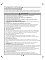
CAUTION
When moving or relocating the air conditioner, consult experienced service
technicians for disconnection and reinstallation of the unit.
Do not place any other electrical products or household belongings under
indoor unit or outdoor unit. Condensation dripping from the unit might get them
wet, and may cause damage or malfunction of your property.
Do not use means to accelerate the defrosting process or to clean, other than
those recommended by the manufacturer.
The appliance shall be stored in a room without continuously operating ignition
sources(for example, open flames, an operating gas appliance or an operating
electric heater).
Do not pierce or burn.
Be aware that refrigerants may not contain an odor.
To keep ventilation openings clear of obstruction.
The appliance shall be stored in a well-ventilated area where the room size
corresponds to the room area as specified for operation.
The appliance shall be stored in a room without continuously operating open
flames (for example an operating gas appliance) and ignition sources (for
example an operating electric heater).

Safety precautions
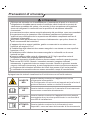
WARNING
This symbol shows that this appliance uses a flammable
refrigerant.
If the refrigerant is leaked and exposed to an external
ignition source, there is a risk of fire
CAUTION
This symbol shows that the operation manual should be
read carefully.
CAUTION
This symbol shows that a service personnel should be
handling this equipment with reference to the
installation manual.
CAUTION
This symbol shows that information is available such as
the operating manual or installation manual.
12
CAUTION
Any person who is involved with working on or breaking into a refrigerant circuit
should hold a current valid certificate from an industry-accredited assessment
authority, which authorises their competence to handle refrigerants safely in
accordance with an industry recognised assessment specification.
Servicing shall only be performed as recommended by the equipment
manufacturer.
Maintenance and repair requiring the assistance of other skilled personnel
shall be carried out under the supervision of the person competent in the use of
flammable refrigerants.
Do not use means to accelerate the defrosting process or to clean, other than
those recommended by the manufacturer.
Appliance shall be installed, operated and stored in a room with a floor
2
arealarger than 10 m .
The installation of pipe-work shall be kept to a a room with a floor area larger
2
than 10 m .
The pipe-work shall be complianced with national gas regulations.
The maximum refrigerant charge amount is 2.5 kg.The specific refrigerant
charge is based on the nameplate of the outdoor unit.
Mechanical connectors used indoors shall comply with ISO 14903. When
mechanical connectors are reused indoors, sealing parts shall be renewed.
When flared joints are reused indoors, the flare part shall be re-fabricated.
The installation of pipe-work shall be kept to a minimum.
Mechanical connections shall be accessible for maintenance purposes.
Explanation of symbols displayed on the indoor unit or outdoor unit.
Caution, risk of fire
C

13
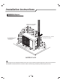
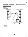
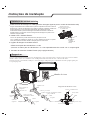
Installation instructions
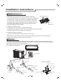
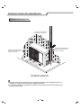
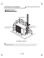
Installation diagram
Above figure is only a simple presentation of the unit, it may not match the external appearance of the unit you purchased.
Installation must be performed in accordance with the national wiring standards by authorized personnel only.
Air intake distance from
the wall should be
over 250mm
Air intake distance from the wall
over 250mm
air outlet distance from the wall
should be over 500mm
should be over 250mm
outdoor unit
Distance from the obstacle
should be over 500mm.

14
Installation instructions
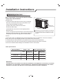
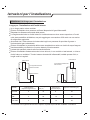
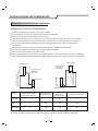
Select the installation locations
Location for Installing Outdoor Unit
Where it is convenient to install and well ventilated.
Avoid installing it where flammable gas could leak.
Keep the required distance apart from the wall.
The pipe length between indoor and outdoor unit should be notmore than 5 meters in factory default
status, but it can go up to maximum 20 meters with additional refrigerant charge.
A fixed base where it is not subject to increased operation noise.
Where there is not any blockage of the air outlet.
Keep the outdoor unit away from greasy dirt,vulcanization gas exit.
Avoid installing it by the roadside where there is a risk of muddy water.
Avoid installing under direct sunlight, in an aisle or sideway, or near heat sources and ventilation fans.
Keep away from flammable materials, thick oil fog, and wet or uneven places.
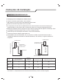
Outdoor unit
Indoor unit
Pipe length is
20 meters Max.
be less than 15m
Height should
Outdoor unit
Indoor unit
Pipe length is
20 meters Max.
be less than 15m
Height should
If the height or pipe length is out of the scope of the table, please consult the merchant.
Model
7K~12K515 820
Max. allowed pipe length
without additional
refrigerant (m)
Limit of
length (m)
pipe Limit of Elevation
Difference H (m)
Required amount of
additional refrigerant (g/m)
18K
21K~25K
520 1520
520 1530

15
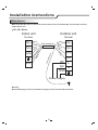
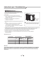
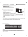
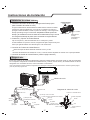
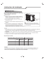
Outdoor Unit
1) Remove the access door from the unit by loosening
the screw. Connect the wires to the terminals on the
control board individually as follows.
2) Secure the power cord onto the control
board with cable clamp.
3) Reinstall the access door to the original position
with the screw.
4) Use a recognized circuit breaker for 24K model between
the power source and the unit. A disconnecting device to
adequately disconnect all supply lines must be fitted.
Note: For some models, it is necessary to remove the cabinet to
connect to the indoor unit terminal.
Access door
Terminal(inside)
Outdoor unit
Installation instructions
Caution:
1. Never fail to have an individual power circuit specifically for the air conditioner. As for the method of
wiring, refer to the circuit diagram posted on the inside of the access door .
2. Comfirm that the cable thickness is as specified in the power source specification.
3. Check the wires and make sure that they are all tightly fastened after cable connection.
4. Be sure to install an earth leakage circuit breaker in wet or moist areas.
The figures in this manual are based on the external
view of a standard model. Consequently, the shape
may differ from that of the air conditioner you have
selected.
Capacity (Btu/h) Power connecting cord
Power cord
Type Type
Normal cross
- sectional area
Normal cross
- sectional area
Cable Specifications
Attention:
The plug must be accessible even after the installation of the appliance in case there is a need to
disconnect it. If not possible, connect appliance to a double-pole switching device with contact
separation of at least 3 mm placed in an accessible position even after installation.
7K,9K,12K H07RN-F 2
1.0mm X3 H07RN-F 2
1.0mm X5
18K
24K
H07RN-F
H07RN-F
2
1.5mm X3
2
2.5mm X3
H07RN-F
H07RN-F
2
1.5mm X5
2
2.5mm X5
Connecting of the Cable

16
Installation instructions
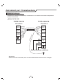
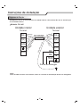
Make sure that the color of the wires in the outdoor unit and terminal No. are the same as those
of the indoor unit.
7K~24K Model
Wiring diagram
2(N)
1(L)
0(L) 0(L)
2(N)
1(L)
Power connecting cord
Blue
Blue
Yellow/Green
Yellow/Green
Brown
Brown
Gray
Gray
Power supply
L
N
BN
BU
YE/GN
Terminal
Indoor unit
Terminal
Outdoor unit
4(SI)
4(SI)
Black
Black
Warning:
Before obtaining access to terminals,all supply circuits must be disconnected.

The air which contains moisture remaining in the refrigeration cycle may cause a malfunction on the
compressor. After connecting the indoor and outdoor units, release air and moisture from the refrigerant
cycle using a vacuum pump, as shown below.
Installation instructions
Air purging
Note: To protect the environment, be sure not to discharge the refrigerant to the air directly.
See next page for air purging steps.
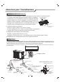
Fix with bolts and nuts tightly on a flat and strong floor.
If installed on the wall or roof, make sure to fix the supporter well to prevent it
from shaking due to serious vibration or strong wind.
3. Outdoor Unit Piping Connection
4. Outdoor Unit Cable Connection (see previous page)
Remove the valve caps from the 2-way and 3-way valve.
Connect the pipes to the 2-way and 3-way valves separately according to the required torque.
2. Install and Fix Outdoor Unit
1. Install Drain Port and Drain Hose (for heat-pump model only)
Drain hose
(prepared by user)
Washer
Drain port
The condensate drains from the outdoor unit when the unit operates
in heating mode. In order not to disturb your neighbor and protect
the environment, install a drain port and a drain hose to direct the
condensate water. Just install the drain port and rubber washer to
the chassis of the outdoor unit, then connect a drain hose to the
port as the right figure demonstrates.
Outdoor unit installation
Rubber pad (optional)
Place under the leg pedestal
17
Refrigerant flow direction 2-way valve
(6) Open 1/4 turn
valve cap
(1) Turn
(8) Tighten
(2) Turn
3-way valve
(8) Tighten
(1) Turn
(7) Turn to fully open the
valve
(7) Turn to fully open the valve
(8) Tighten
3-way valve diagram
connect to indoor unit
open position
spindle
service port cap
Service
port
Connect to outdoor unit
Valve core
needle
indoor unit
Valve cap
Vacuum pump

(1) Unscrew and remove caps from 2 and 3-way valves.
(2) Unscrew and remove cap from service valve.
(3) Connect vacuum pump flexible hose to the service valve.
(4) Start vacuum pump for 10-15 minutes until reaching a vacuum of 10 mm Hg absolutes.
(5) With vacuum pump still running close the low pressure knob on vacuum pump manifold. Then stop
the vacuum pump.
(6) Open 2-way valve ,1/4 turn, then close it after 10 seconds. Check tightness of all joints using liquid
soap or an electronic leak detector.
(7) Turn 2 and 3-way valves stem to fully open the valves. Disconnect the flexible vacuum pump hose.
(8) Replace and tighten all valve caps.
How to Purge Air Tubes:
Installation instructions
18
A página está carregando...
A página está carregando...
A página está carregando...
A página está carregando...
A página está carregando...
A página está carregando...
A página está carregando...
A página está carregando...
A página está carregando...
A página está carregando...
A página está carregando...
A página está carregando...
A página está carregando...
A página está carregando...
A página está carregando...
A página está carregando...
A página está carregando...
A página está carregando...
A página está carregando...
A página está carregando...
A página está carregando...
A página está carregando...
A página está carregando...
A página está carregando...
A página está carregando...
A página está carregando...
A página está carregando...
A página está carregando...
A página está carregando...
A página está carregando...
A página está carregando...
A página está carregando...
A página está carregando...
A página está carregando...
A página está carregando...
A página está carregando...
A página está carregando...
A página está carregando...
A página está carregando...
A página está carregando...
A página está carregando...
A página está carregando...
A página está carregando...
A página está carregando...
A página está carregando...
A página está carregando...
A página está carregando...
A página está carregando...
A página está carregando...
A página está carregando...
A página está carregando...
A página está carregando...
A página está carregando...
A página está carregando...
A página está carregando...
A página está carregando...
A página está carregando...
A página está carregando...
A página está carregando...
A página está carregando...
-
 1
1
-
 2
2
-
 3
3
-
 4
4
-
 5
5
-
 6
6
-
 7
7
-
 8
8
-
 9
9
-
 10
10
-
 11
11
-
 12
12
-
 13
13
-
 14
14
-
 15
15
-
 16
16
-
 17
17
-
 18
18
-
 19
19
-
 20
20
-
 21
21
-
 22
22
-
 23
23
-
 24
24
-
 25
25
-
 26
26
-
 27
27
-
 28
28
-
 29
29
-
 30
30
-
 31
31
-
 32
32
-
 33
33
-
 34
34
-
 35
35
-
 36
36
-
 37
37
-
 38
38
-
 39
39
-
 40
40
-
 41
41
-
 42
42
-
 43
43
-
 44
44
-
 45
45
-
 46
46
-
 47
47
-
 48
48
-
 49
49
-
 50
50
-
 51
51
-
 52
52
-
 53
53
-
 54
54
-
 55
55
-
 56
56
-
 57
57
-
 58
58
-
 59
59
-
 60
60
-
 61
61
-
 62
62
-
 63
63
-
 64
64
-
 65
65
-
 66
66
-
 67
67
-
 68
68
-
 69
69
-
 70
70
-
 71
71
-
 72
72
-
 73
73
-
 74
74
-
 75
75
-
 76
76
-
 77
77
-
 78
78
-
 79
79
-
 80
80


Hisense R32 Air Conditioner Manual do usuário
- Categoria
- Condicionadores de ar de sistema split
- Tipo
- Manual do usuário
em outras línguas
Outros documentos
-
HTW MULTISPLIT IX21D4 Guia de instalação
-
Infiniton SPLIT-3908TP Manual do proprietário
-
EAS ELECTRIC MAJESTIC25K Manual do usuário
-
Becken AR COND PORTATIL 12000BTU BAC4255 Manual do proprietário
-
-
Jocel JACP9030733 Manual do usuário
-
mundoclima H9A Serie Guia de instalação
-
Infiniton PAC-W12 Manual do proprietário
-
-