thinkcar SOC-Thinktool-S02-FBA Manual do usuário
- Tipo
- Manual do usuário

ENFRESDEITPTJP
User Manual

EN
I
www.mythinkcar.com
Content
1. Quick Start Manual ........................................................................................................1
1.1 Initial Use .......................................................................................................................1
1.1.1 Turn on the Machine ............................................................................................1
1.1.2 Appearance and Functions ..................................................................................1
1.1.3 Language Setting .................................................................................................1
1.1.4 Connect WIFI .......................................................................................................2
1.1.5 Choose Time Zone ..............................................................................................2
1.1.6 Create an Account ................................................................................................ 2
1.1.7 Typing in Repair Shop Information .......................................................................3
1.1.8 User Agreement ...................................................................................................3
1.2 Selection and Purchase of Diagnostic Software............................................................3
1.3 Plug-in and Plug-out of the Diagnostic Cable ................................................................4
1.4 Printer Installation .......................................................................................................4
2 General information .......................................................................................................7
2.1 On-Board Diagnostics (OBD) II ....................................................................................7
2.2 Diagnostic Trouble Codes (DTCs) ................................................................................7
2.3 Data Link Connector (DLC) Location ............................................................................8
2.4 OBD II Readiness Monitors ..........................................................................................9
2.5 OBD II Monitor Readiness Status ...............................................................................10
2%',,'H¿QLWLRQV .......................................................................................................10
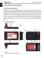
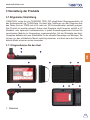
3. Introduction to the Product ........................................................................................12
3.1 General introductions .................................................................................................12
3.1.1 Diagnostic host ................................................................................................... 12
3.1.2 Technical indications .........................................................................................14
4 Preparation ....................................................................................................................15
4.1 Charge the host ..........................................................................................................15
4.2 Battery ........................................................................................................................15
4.3 Power on and off .........................................................................................................16
4.3.1 Power on ...........................................................................................................16
4.3.2 Power off ..........................................................................................................16
5 Functions Descriptions .............................................................................................. 16
5.1 Diagnosis ....................................................................................................................16
5.2 Maintenance ...............................................................................................................23

EN
II
www.mythinkcar.com
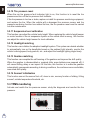
5.2.1 Maintenance light reset ......................................................................................23
5.2.2 Steering angle reset ...........................................................................................23
5.2.3 Battery matching ................................................................................................24
5.2.4 ABS exhaust ....................................................................................................... 24
5.2.5 Throttle matching ..............................................................................................24
5.2.6 Brake pad reset ..................................................................................................25
5.2.7 DPF regeneration ...............................................................................................25
5.2.8 Anti-theft matching .............................................................................................25
5.2.9 Nozzle coding ..................................................................................................... 25
5.2.10 Tire pressure reset ...........................................................................................26
5.2.11 Suspension level calibration .............................................................................26
5.2.12 Headlight matching ..........................................................................................26
5.2.13 Gearbox matching ............................................................................................26
5.2.14 Sunroof initialization .........................................................................................26
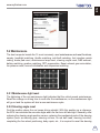
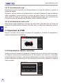
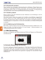
5.3 TPMS monitoring ........................................................................................................26
5.4 Quick Check and Printing ...........................................................................................27
5.5 ThinkStore ...................................................................................................................27
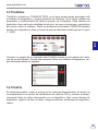
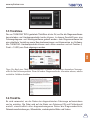
5.6 ThinkFile ...................................................................................................................... 28
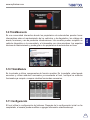
5.7 Repair info ...................................................................................................................28
5.8 Remote Diagnosis ......................................................................................................28
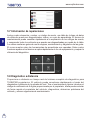
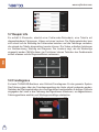
5.9 ThinkMoments ............................................................................................................. 29
5.10 ThinkModule .............................................................................................................. 29
5.11 Settings .....................................................................................................................29
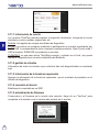
5.11.1 Account information ..........................................................................................30
5.11.2 Customer management ...................................................................................30
5.11.3 Repair shop information ..................................................................................30
5.11.4 Internet connection ..........................................................................................30
5.11.5 Firmware upgrade ............................................................................................30
5.11.6 Language ........................................................................................................31
5.11.7 Time zone ........................................................................................................31
6. Q&A ...............................................................................................................................31
Warranty Terms ................................................................................................................. 31

EN
1
www.mythinkcar.com
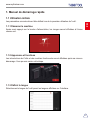
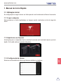
1. Quick Start Manual
1.1 Initial Use
The following settings should be made when you initially use the tool.
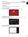
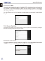
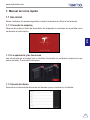
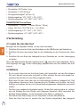
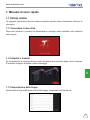
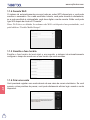
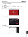
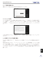
1.1.1 Turn on the Machine
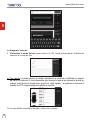
After pressing the power button, images will be shown on the screen as follows.
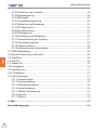
1.1.2 Appearance and Functions
Introductions to the host computer and functional modules will be shown after it is turned
on. You can choose to skip this step.
1.1.3 Language Setting
Select the tool language from the languages displayed on the interface.

EN
2
www.mythinkcar.com
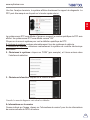
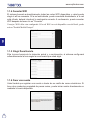
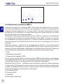
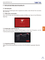
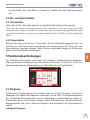
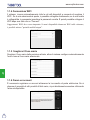
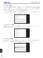
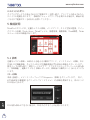
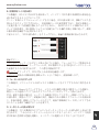
1.1.4 Connect WIFI
The system will automatically search all available WIFI networks and you can choose the
WIFI needed. If the chosen network is open, you can connect it directly; If the chosen
network is encrypted, you must enter the correct password. Then You can connect WIFI
after clicking “connect”.
Tips: Wi-Fi must be set. If no Wi-Fi network is available nearby, you can enable "Portable Mobile
Hotspot".
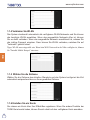
1.1.5 Choose Time Zone
&KRRVHWKHWLPH]RQHRIWKHFXUUHQWORFDWLRQWKHQWKHV\VWHPZLOODXWRPDWLFDOO\FRQ¿JXUH
the time according to the time zone you chose.
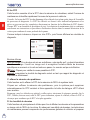
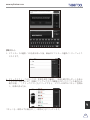
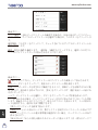
1.1.6 Create an Account
You need to register an account through your e-mail box. If you have owned other products
of THINK series, you can directly log in by using the account available.

EN
3
www.mythinkcar.com
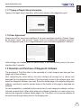
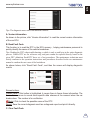
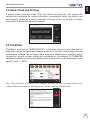
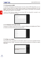
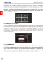
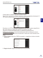
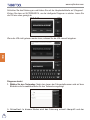
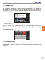
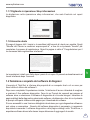
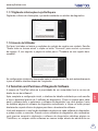
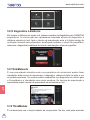
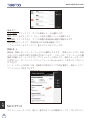
1.1.7 Typing in Repair Shop Information
Typing in the repair shop information, which will be shown in the diagnostic report.
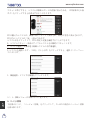
1.1.8 User Agreement
Please read all the terms and conditions of the user agreement carefully. Choose “Agree
all the above terms”, and click the “Agree” button to complete the registration process.
Then the page will jump to the “Congratulations on your successful registration” interface.
Initial settings are finished after the above steps. It will automatically jump to the work
interface after 3 seconds.
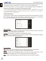
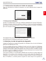
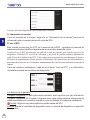
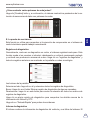
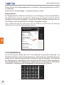
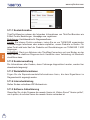
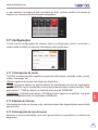
1.2 Selection and Purchase of Diagnostic Software
The purchase of ThinkTool refers to the ownership of a host computer and one-year free
XVDJHULJKWRI¿YHVRIWZDUH
After completing the initial setting, the work interface will prompt you to choose and
GRZQORDG¿YHIUHHGLDJQRVWLFVRIWZDUH&OLFNWKHSURPSWWRMXPSWRWKHVRIWZDUHVWRUHDQG
select the diagnostic software you need. Enter the details page of the selected diagnostic
software, and directly click the prompt button at the bottom of the page to download the
software.
You are accessible to a detailed function introduction to each diagnostic software, and can
rate and comment them. When other diagnostic software is needed, you need to buy it by
entering the diagnostic software details page in the ThinkStore, or buy several software at
the same time through adding them to the shopping cart.

EN
4
www.mythinkcar.com
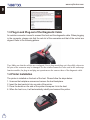
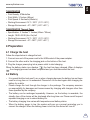
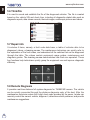
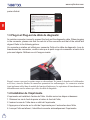
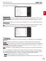
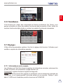
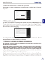
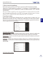
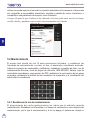
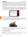
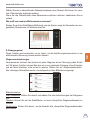
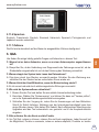
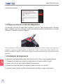
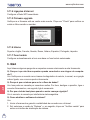
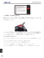
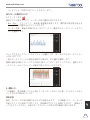
1.3 Plug-in and Plug-out of the Diagnostic Cable
An aviation connector is used to connect the host and the diagnostic cable. When plugging
in the connector, please note that the red dot of the connector and that of the socket are
aligned. Refer to the following picture:
Tips: Make sure that the red dots are overlapped. Never plug in and plug out it forcefully, otherwise
the pins of the connector may be damaged. As the aviation connector is also used in the endoscope
function module, the plug-in and plug-out operations are the same as those of the diagnostic cable.
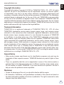
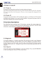
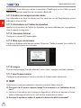
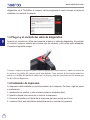
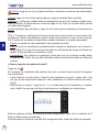
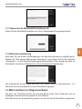
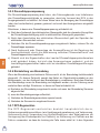
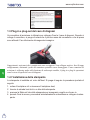
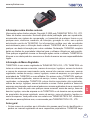
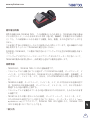
1.4 Printer Installation
The printer is installed on the back of the host. Please follow the steps below:
1. Unscrew the backplane screws and remove the host backplane.
2. Insert the host card slot into one side of the printer
.
3. Press the buckle on the side of the printer to snap on it into the host
.
4. When the host is on, it will automatically identify and connect the printer.

EN
5
www.mythinkcar.com
Copyright Information
Copyright Information Copyright © 2020 by THINKCAR TECH. CO., LTD. All rights
reserved. No part of this publication may be reproduced, stored in a retrieval system,
or transmitted in any form or by any means, electronic, mechanical, photocopying and
recording or otherwise, without the prior written permission of THINKCAR. The information
contained herein is designed only for the use of this unit. THINKCAR is not responsible
for any use of this information as applied to other units. Statement: THINKCAR owns the
complete intellectual property rights for the software used by this product. For any reverse
engineering or cracking actions against the software, THINKCAR will block the use of this
product and reserve the right to pursue their legal liabilities.
Trademark Information
THINKTOOL is a registered trademark of THINKCAR TECH CO., LTD. All other
THINKTOOL trademarks, service marks, domain names, logos, and company names
referred to in this manual are either trademarks, registered trademarks, service marks,
domain names, logos, company names of or are otherwise the property of THINKCAR
or its affiliates. In countries where any of the THINKTOOL trademarks, service marks,
domain names, logos and company names are not registered, THINKTOOL claims other
rights associated with unregistered trademarks, service marks, domain names, logos,
and company names. Other products or company names referred to in this manual
may be trademarks of their respective owners. You may not use any trademark, service
mark, domain name, logo, or company name of THINKTOOL or any third party without
permission from the owner of the applicable trademark, service mark, domain name, logo,
or company name. You may contact THINKCAR TECH INC by visiting the website at www.
mythinkcar.com, or writing to THINKCAR TECH CO., LTD.
General Notice
Other product names used herein are for identification purposes only and may be
trademarks of their respective owners. THINKCAR disclaims any and all rights in those
marks.
There is a possibility that this unit is inapplicable to some of the vehicle models or
systems listed in the diagnosis section due to different countries, areas, and/or years.
Do not hesitate to contact THINKCAR if you come across such questions. We are to
help you solve the problem as soon as possible.
Disclaimer
7RWDNHIXOODGYDQWDJHRIWKHXQLW\RXVKRXOGEHIDPLOLDUZLWKWKHHQJLQH
$OOLQIRUPDWLRQLOOXVWUDWLRQVDQGVSHFL¿FDWLRQVFRQWDLQHGLQWKLVPDQXDODUHEDVHGRQ
the latest information available at the time of publication. The right is reserved to make
change at any time without notice.

EN
6
www.mythinkcar.com
1HLWKHU7+,1.&$5QRULWVDI¿OLDWHVVKDOOEHOLDEOHWRWKHSXUFKDVHURIWKLVXQLWRUWKLUG
parties for damages, losses, costs or expenses incurred by purchaser or third parties
as a result of: accident, misuse, or abuse of this unit, or unauthorized modifications,
repairs, or alterations to this unit, or failure to strictly comply with THINKCAR operating
and maintenance instructions.
7+,1.&$5VKDOOQRWEHOLDEOHIRUDQ\GDPDJHVRUSUREOHPVDULVLQJIURPWKHXVHRIDQ\
options or any consumable products other than those designated as Original THINKCAR
Products or THINKCAR Approved Products by THINKCAR.
Safety Precautions and Warnings
To prevent personal injury or damage to vehicles and/or this tool, please read this user’s
PDQXDO¿UVWFDUHIXOO\DQGREVHUYHWKHIROORZLQJVDIHW\SUHFDXWLRQVDWDPLQLPXPZKHQHYHU
working on a vehicle:
$OZD\VSHUIRUPDXWRPRWLYHWHVWLQJLQDVDIHHQYLURQPHQW
'RQRWDWWHPSWWRRSHUDWHRUREVHUYHWKHWRROZKLOHGULYLQJDYHKLFOH2SHUDWLQJRU
observing the tool will cause driver distraction and could cause a fatal accident.
:HDUVDIHW\H\HSURWHFWLRQWKDWPHHWV$16,VWDQGDUGV
.HHSFORWKLQJKDLUKDQGVWRROVWHVWHTXLSPHQWHWFDZD\IURPDOOPRYLQJRUKRW
engine parts.
2SHUDWHWKHYHKLFOHLQDZHOOYHQWLODWHGZRUNDUHD([KDXVWJDVHVDUHSRLVRQRXV
3XWEORFNVLQIURQWRIWKHGULYHZKHHOVDQGQHYHUOHDYHWKHYHKLFOHXQDWWHQGHGZKLOH
running tests.
8VHH[WUHPHFDXWLRQZKHQZRUNLQJDURXQGWKHLJQLWLRQFRLOGLVWULEXWRUFDSLJQLWLRQZLUHV
and spark plugs. These components create hazardous voltages when the engine is
running.
3XWWKHWUDQVPLVVLRQLQ3IRU$7RU1IRU07DQGPDNHVXUHWKHSDUNLQJEUDNHLV
engaged.
.HHSD¿UHH[WLQJXLVKHUVXLWDEOHIRUJDVROLQHFKHPLFDOHOHFWULFDO¿UHVQHDUE\
'RQ¶WFRQQHFWRUGLVFRQQHFWDQ\WHVWHTXLSPHQWZKLOHWKHLJQLWLRQLVRQRUWKHHQJLQHLV
running.
.HHSWKLVWRROGU\FOHDQIUHHIURPRLOZDWHURUJUHDVH8VHDPLOGGHWHUJHQWRQDFOHDQ
cloth to clean the outside of the tool, when necessary.
3OHDVHXVHWKH'& 5V power adaptor to charge this tool. No responsibility can be
assumed for any damage or loss caused as a result of using power adaptors other than
the right one.
An Introduction to the company
THINKCAR TECH is a highly creative developer of vehicle diagnosis tools. By marrying

EN
7
www.mythinkcar.com
user-friendly creative ideas with technologies, the company has produced Think se-
ries products featured as ultimate experience and extraordinary imagination, including
THINKOBD
ˈ
THINKSAN, THINKCAR, THINKDIAG, THINKPLUS, THINKSCAN and
THINKTOOL. Those products prove to be a brand new generation of diagnosis tools
through user-oriented creative products forms and service system. THINKCAR TECH
keeps striving for perfection in all aspects such as its products design, material selection,
manufacturing and software service.
2 General information
2.1 On-Board Diagnostics (OBD) II
The first generation of On-Board Diagnostics (OBD I) was developed by the California
Air Resources Board (ARB) and implemented in 1988 to monitor some of the emission
control components on vehicles. As technology evolved and the desire to improve the On-
Board Diagnostic system increased, a new generation of On-Board Diagnostic system
was developed. This second generation of OnBoard Diagnostic regulations is called “OBD
II”. The OBD II system is designed to monitor emission control systems and key engine
FRPSRQHQWVE\SHUIRUPLQJHLWKHUFRQWLQXRXVRUSHULRGLFWHVWVRIVSHFL¿FFRPSRQHQWVDQG
vehicle conditions. When a problem is detected, the OBD II system turns on a warning
lamp (MIL) on the vehicle instrument panel to alert the driver typically by the phrase of
“Check Engine” or “Service Engine Soon”. The system will also store important information
about the detected malfunction so that a technician can accurately find and fix the
problem. Here below follow three pieces of such valuable information:
1) Whether the Malfunction Indicator Light (MIL) is commanded ‘on’ or ‘off’;
2) Which, if any, Diagnostic Trouble Codes (DTCs) are stored;
3) Readiness Monitor status.
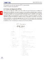
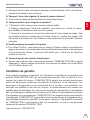
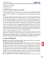
2.2 Diagnostic Trouble Codes (DTCs)
OBD II Diagnostic Trouble Codes are codes that are stored by the on-board computer
diagnostic system in response to a problem found in the vehicle. These codes identify a
particular problem area and are intended to provide you with a guide as to where a fault
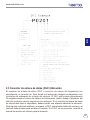
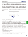
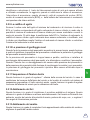
PLJKWEHRFFXUULQJZLWKLQDYHKLFOH2%',,'LDJQRVWLF7URXEOH&RGHVFRQVLVWRID¿YH
GLJLWDOSKDQXPHULFFRGH7KH¿UVWFKDUDFWHUDOHWWHULGHQWL¿HVZKLFKFRQWUROV\VWHPVHWV
the code. The second character, a number, 0-3; other three characters, a hex character,
0-9 or A-F provide additional information on where the DTC originated and the operating
conditions that caused it to set. Here below is an example to illustrate the structure of the
digits:

EN
8
www.mythinkcar.com
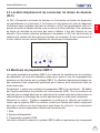
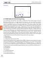
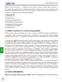
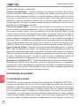
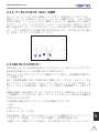
2.3 Data Link Connector (DLC) Location
The DLC (Data Link Connector or Diagnostic Link Connector) is typically a 16pin connector
where diagnostic code readers interface with the vehicle’s onboard computer. The DLC is
usually located 12 inches from the center of the instrument panel (dash), under or around
the driver’s side for most vehicles. If Data Link Connector is not located under dashboard,
a label should be there telling location. For some Asian and European vehicles, the DLC
is located behind the ashtray and the ashtray must be removed to access the connector. If
the DLC cannot be found, refer to the vehicle’s service manual for the location.

EN
9
www.mythinkcar.com
2.4 OBD II Readiness Monitors
An important part of a vehicle’s OBD II system is the Readiness Monitors, which are
LQGLFDWRUVXVHGWR¿QGRXWLIDOORIWKHHPLVVLRQVFRPSRQHQWVKDYHEHHQHYDOXDWHGE\WKH
2%',,V\VWHP7KH\DUHUXQQLQJSHULRGLFWHVWVRQVSHFL¿FV\VWHPVDQGFRPSRQHQWVWR
ensure that they are performing within allowable limits.
&XUUHQWO\WKHUHDUHHOHYHQ2%',,5HDGLQHVV0RQLWRUVRU,00RQLWRUVGH¿QHGE\WKH
U.S. Environmental Protection Agency (EPA). Not all monitors are supported in every
vehicles and the exact number of monitors in any vehicle depends on the motor vehicle
manufacturer’s emissions control strategy.
Continuous Monitors -- Some of the vehicle components or systems are continuously
WHVWHGE\WKHYHKLFOH¶V2%',,V\VWHPZKLOHRWKHUVDUHWHVWHGRQO\XQGHUVSHFL¿FYHKLFOH
operating conditions. The continuously monitored components listed below are always
ready:
0LV¿UH
2. Fuel System
3. Comprehensive Components (CCM)
Once the vehicle is running, the OBD II system is continuously checking the above
FRPSRQHQWVPRQLWRULQJNH\HQJLQHVHQVRUVZDWFKLQJIRUHQJLQHPLV¿UHDQGPRQLWRULQJ
fuel demands.
Non-Continuous Monitors -- Unlike the continuous monitors, many emissions and engine
V\VWHPFRPSRQHQWVUHTXLUHWKHYHKLFOHWREHRSHUDWHGXQGHUVSHFL¿FFRQGLWLRQVEHIRUHWKH
monitor is ready. These monitors are termed noncontinuous monitors and are listed below:
1) EGR System
2) O2 Sensors
3) Catalyst
4) Evaporative System
5) O2 Sensor Heater
6) Secondary air Injection

EN
10
www.mythinkcar.com
7) Heated Catalyst
8) A/C system
2.5 OBD II Monitor Readiness Status
OBD II systems must indicate whether or not the vehicle’s PCM’s monitor system has
completed testing on each component. Components that have been tested will be reported
as “Ready”, or “Complete”, meaning they have been tested by the OBD II system.
The purpose of recording readiness status is to allow inspectors to determine if the
vehicle’s OBD II system has tested all the components and/or systems. The Powertrain
Control Module (PCM) sets a monitor to “Ready” or “Complete” after an appropriate drive
cycle has been performed. The drive cycle that enables a monitor and sets readiness
codes to “Ready” varies for each individual monitor. Once a monitor is set as “Ready”
or “Complete”, it will remain in this state. A number of factors, including erasing of
Diagnostic Trouble Codes (DTCs) with a code reader or a disconnected battery, can result
in Readiness Monitors being set to “Not Ready”. Since the three continuous monitors
are constantly evaluating, they will be reported as “Ready” all of the time. If testing of a
particular supported non-continuous monitor has not been completed, the monitor status
will be reported as “Not Complete” or “Not Ready.”
In order for the OBD monitor system to become ready, the vehicle should be driven under
a variety of normal operating conditions. These operating conditions may include a mix of
highway driving and stop and go, city type driving, and at least one overnight-off period.
For specific information on getting your vehicle’s OBD monitor system ready, please
consult your vehicle owner’s manual.
2%',,'H¿QLWLRQV
Powertrain Control Module (PCM) -- OBD II terminology for the on-board computer that
controls engine and drive train.
Malfunction Indicator Light (MIL) -- Malfunction Indicator Light (Service Engine Soon,
Check Engine) is a term used for the light on the instrument panel. It is to alert the driver
and/or the repair technician that there is a problem with one or more of vehicle’s systems
and may cause emissions to exceed federal standards. If the MIL illuminates with a steady
light, it indicates that a problem has been detected and the vehicle should be serviced
DVVRRQDVSRVVLEOH8QGHUFHUWDLQFRQGLWLRQVWKHGDVKERDUGOLJKWZLOOEOLQNRUÀDVK7KLV
LQGLFDWHVDVHYHUHSUREOHPDQGÀDVKLQJLVLQWHQGHGWRGLVFRXUDJHYHKLFOHRSHUDWLRQ7KH
vehicle onboard diagnostic system cannot turn the MIL off until the necessary repairs are
completed or the condition no longer exists.
DTC -- Diagnostic Trouble Codes (DTC) that identifies which section of the emission
control system has malfunctioned.
Enabling Criteria$OVRWHUPHG(QDEOLQJ&RQGLWLRQV7KH\DUHWKHYHKLFOHVSHFL¿FHYHQWV
or conditions that must occur within the engine before the various monitors will set, or

EN
11
www.mythinkcar.com
run. Some monitors require the vehicle to follow a prescribed “drive cycle” routine as part
of the enabling criteria. Drive cycles vary among vehicles and for each monitor in any
SDUWLFXODUYHKLFOH3OHDVHUHIHUWRWKHYHKLFOH¶VIDFWRU\VHUYLFHPDQXDOIRUVSHFL¿FHQDEOLQJ
procedures.
OBD II Drive Cycle -- A specific mode of vehicle operation that provides conditions
required to set all the readiness monitors applicable to the vehicle to the “ready” condition.
The purpose of completing an OBD II drive cycle is to force the vehicle to run its onboard
diagnostics. Some form of a drive cycle needs to be performed after DTCs have been
erased from the PCM’s memory or after the battery has been disconnected. Running
through a vehicle’s complete drive cycle will “set” the readiness monitors so that future
faults can be detected. Drive cycles vary depending on the vehicle and the monitor that
QHHGVWREHUHVHW)RUYHKLFOHVSHFL¿FGULYHF\FOHFRQVXOWWKHVHUYLFHPDQXDO
Freeze Frame Data -- When an emissions related fault occurs, the OBD II system not
only sets a code but also records a snapshot of the vehicle operating parameters to help
in identifying the problem. This set of values is referred to as Freeze Frame Data and may
LQFOXGHLPSRUWDQWHQJLQHSDUDPHWHUVVXFKDVHQJLQH530YHKLFOHVSHHGDLUÀRZHQJLQH
load, fuel pressure, fuel trim value, engine coolant temperature, ignition timing advance, or
closed loop status.
Fuel Trim (FT) -- Feedback adjustments to the base fuel schedule. Short-term fuel trim
refers to dynamic or instantaneous adjustments. Long-term fuel trim refers to much more
gradual adjustments to the fuel calibration schedule than short-term trim adjustments.
These long-term adjustments compensate for vehicle differences and gradual changes
that occur over time.

EN
12
www.mythinkcar.com
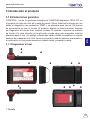
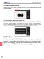
3. Introduction to the Product
3.1 General introductions
THINKTOOL, one of the diagnostic products launched by THINKCAR TECH INC, is
the highest-level product of the THINK series. It boasts all the functions ranging from
diagnosis, testing to TPMS, and is suitable for more than 160 automotive brands
worldwide.The product adopts a modular design. In addition to the diagnostic host
computer, it also contains 12 standard or optional function modules. In each application
scenario, you can choose to assemble different modules for usage. A quick disassembly
and assembly interface is set on the back of the host computer. You just need to insert
the required module gently, and then the host can recognize the current module and start
using it.
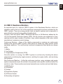
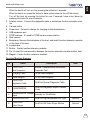
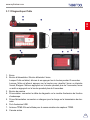
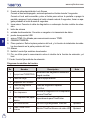
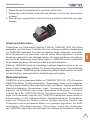
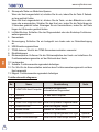
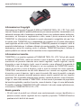
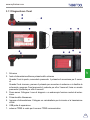
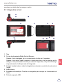
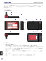
3.1.1 Diagnostic host
1
.
Screen
2
.
Power source/Lock screen button

EN
13
www.mythinkcar.com
When the host is off, turn on it by pressing the button for 3 seconds.
When the host is on, press the button to wake up the screen or turn off the screen;
Turn off the host by pressing the button for over 3 seconds; force a shut down by
pressing the button for over 8 seconds.
3
.
Aviation socket
:
Connect the diagnostic cable or endoscope function extension mod-
ule.
4
.
Camera button
5
.
Power inlet
:
Connect a charger for charging or data transmission.
6
.
USB expansion port
7
.
TPMS antenna
:
It’s used for TPMS sensor communication.
8
.
Rear camera
9
.
Backplane: Remove the backplane of the host, and install function extension modules
on the back of the host.
10
.
Loudspeaker
11
.
Buckle
:
Fasten function extension modules.
12
.
Pin: It’s used for communication between the function extension module and the host.
13
.
Magnet
:
Fasten function extension modules.
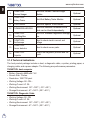
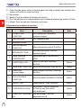
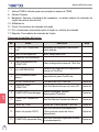
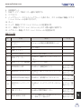
Function Modules Diagram:
No. Name Description Note
1
THINKTOOL
Host Computer
Modular Comprehensive Automotive
Diagnostic Tool
2 Charging Cable For the host computer
3 Power Adapter For the host computer
4
THINKTOOL
Diagnostic Cable
ThinkTool Special Diagnostic Cable
5 THINKPRINTER
ThinkTool Diagnostic Report Thermal
Printer
6
THINKPRINTER Thermal
Paper
Specially for ThinkPrinter
7 THINKWORKLIGHT ThinkTool High-Brightness LED Light Optional
8
THINKTOOL
Video Scope
ThinkTool HD Video Scope Module Optional

EN
14
www.mythinkcar.com
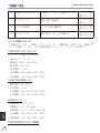
9
THINKTOOL
Thermal Imager
ThinkTool Infrared Thermal Imager
Module
Optional
10
THINKTOOL
Battery Tester
ThinkTool Battery Tester Module Optional
11 TPMS Sensor ThinkTool Special TPMS Sensor Optional
12 THINKMODULEDOCK
ThinkTool Modules Connected to the
Dock can be Used Independently
Optional
13
THINKTOOL
ThinkDiag Box
ThinkTool Wireless Diagnostics Storage
Box
Optional
14
THINKTOOL
Oscilloscope
Used to check electric current and
voltage
Optional
15
THINKTOOL
Sensor detector
Used to check sensor parts Optional
16
THINKTOOL
Projector
Project the diagnostic process and the
report
Optional
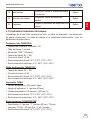
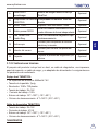
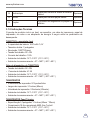
3.1.2 Technical indications
The host product package includes a host, a diagnostic cable, a printer, printing paper, a
charging cable, and a power adapter. The following are performance parameters.
THINKTOOL host computer
Battery Capacity:4850mAh 7.4V
Screen Size: 7inches
Resolution: 1280*720 pixel
Working Voltage: 9V~18V
ᄍ
:RUNLQJ&XUUHQW$
Working Environment: 14
̧
~122
̧
(-10
ć
~50
ć
)
Storage Environment: -4
̧
~140
̧
(-20
ć
~60
ć
)
THINKTOOL Diagnostic Cable
Working Voltage: 9V~18V
:RUNLQJ&XUUHQW$
Working Environment: 14
̧
~122
̧
(-10
ć
~50
ć
)
Storage Environment: -4
̧
~140
̧
(-20
ć
~60
ć
)

EN
15
www.mythinkcar.com
THINKPRINTER
Print Density: 576dots/line
Print Width: 3.1inches (80mm)
Print Speed: 2.3inches/s (60mm/s)
Working Environment: 14
̧
~122
̧
(-10
ć
~50
ć
)
Storage Environment: -4
̧
~140
̧
(-20
ć
~60
ć
)
THINKPRINTER Thermal Paper
6SHFL¿FDWLRQLQFKHVLQFKHVPPPP
Length: 19.6ft~22.9ft (6m~7m)/roll
Working Environment: 14
̧
~122
̧
(-10
ć
~50
ć
)
Storage Environment: -4
̧
~140
̧
(-20
ć
~60
ć
)
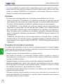
4 Preparation
4.1 Charge the host
Follow the steps below to charge the host:
1. Connect one end of the power cord to the USB socket of the power adapter.
2. Connect the other end to the charging jack on the bottom of the host.
3. Plug the charger power plug into a power outlet to start charging.
When the battery status icon displays
, the host has been charged. When it displays
, the charging process has been completed and you shall disconnect the host.
4.2 Battery
It is normal that the host won’t turn on when charging because the battery has not been
used for a long time or it is exhausted. Please turn on the host again after charging the
battery for a while.
Please charge the host through the charger in the package. The company assumes
no responsibility for damages and losses caused by charging with chargers other than
WKRVHVSHFL¿HGE\WKHFRPSDQ\
The battery can be recharged repeatedly. However, as the battery is wearable, the
standby time of the device will be shortened after long-time use. Please avoid frequent
repeated charging so as to extend battery life.
The battery charging time varies with temperature and battery status.
When the battery power is low, the system will pop up a prompt reminding you to
connect the charger. When the battery power is too low, the device will turn off.

EN
16
www.mythinkcar.com
4.3 Power on and off
4.3.1 Power on
Long press the power button and then the start interface will appear.
7LSV7KHGHYLFHPD\IDLOWRWXUQRQLI\RXXVHLWIRUWKH¿UVWWLPHRUKDYHQ¶WXVHGLWIRUDORQJWLPH
This may be caused by too low battery power. Please try to turn it on again after charging the device
for a while.
4.3.2 Power off
Long press the power button until the dialog box pops up, and then turn off the device
according to the prompts. If you need to force shutdown, long press the power button for
more than 8 seconds until the screen goes dark.
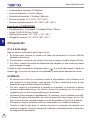
5 Functions Descriptions
The ThinkTool host computer have 10 functions, namely, full system diagnosis,
maintenance, tire pressure monitoring, quick test and printing, ThinkStore, ThinkFile, repair
information, remote diagnosis, ThinkMoments, and ThinkModule.
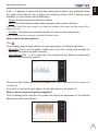
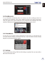
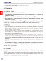
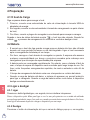
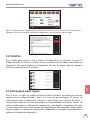
5.1 Diagnosis
Full system diagnosis: it supports more than 160 automobile brands, smart diagnosis
and traditional diagnosis covering OBD II full-function diagnosis, full-system and full-
function diagnosis: read fault codes, clear fault codes, read real-time data streams, special
functions, motion tests, etc.. A diagnostic report will be automatically generated after the
diagnosis.
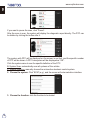
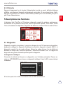
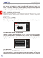
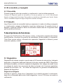
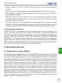
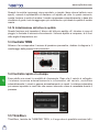
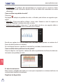
Smart diagnosis
Connect the vehicle and click “Diagnose” on the main interface. Then, click AUTOSEARCH
to start smart diagnosis. Read the VIN as shown below.

EN
17
www.mythinkcar.com
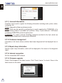
If it fails to read VIN, you need to enter VIN manually.
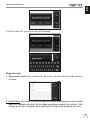
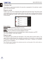
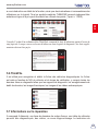
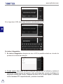
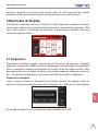
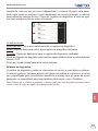
Diagnosis starts
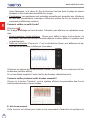
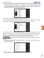
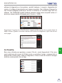
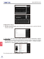
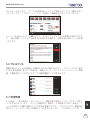
1. Choose test mode: after reading VIN, the screen will enter the test mode selection
interface:
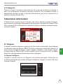
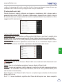
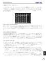
A. Health Report: this mode is to quickly check the vehicle and display the vehicle health
report (it’s available only when the the diagnosis software support this function). After
clicking “quick test”, the system starts scanning DTC respectively and show the result.
A página está carregando...
A página está carregando...
A página está carregando...
A página está carregando...
A página está carregando...
A página está carregando...
A página está carregando...
A página está carregando...
A página está carregando...
A página está carregando...
A página está carregando...
A página está carregando...
A página está carregando...
A página está carregando...
A página está carregando...
A página está carregando...
A página está carregando...
A página está carregando...
A página está carregando...
A página está carregando...
A página está carregando...
A página está carregando...
A página está carregando...
A página está carregando...
A página está carregando...
A página está carregando...
A página está carregando...
A página está carregando...
A página está carregando...
A página está carregando...
A página está carregando...
A página está carregando...
A página está carregando...
A página está carregando...
A página está carregando...
A página está carregando...
A página está carregando...
A página está carregando...
A página está carregando...
A página está carregando...
A página está carregando...
A página está carregando...
A página está carregando...
A página está carregando...
A página está carregando...
A página está carregando...
A página está carregando...
A página está carregando...
A página está carregando...
A página está carregando...
A página está carregando...
A página está carregando...
A página está carregando...
A página está carregando...
A página está carregando...
A página está carregando...
A página está carregando...
A página está carregando...
A página está carregando...
A página está carregando...
A página está carregando...
A página está carregando...
A página está carregando...
A página está carregando...
A página está carregando...
A página está carregando...
A página está carregando...
A página está carregando...
A página está carregando...
A página está carregando...
A página está carregando...
A página está carregando...
A página está carregando...
A página está carregando...
A página está carregando...
A página está carregando...
A página está carregando...
A página está carregando...
A página está carregando...
A página está carregando...
A página está carregando...
A página está carregando...
A página está carregando...
A página está carregando...
A página está carregando...
A página está carregando...
A página está carregando...
A página está carregando...
A página está carregando...
A página está carregando...
A página está carregando...
A página está carregando...
A página está carregando...
A página está carregando...
A página está carregando...
A página está carregando...
A página está carregando...
A página está carregando...
A página está carregando...
A página está carregando...
A página está carregando...
A página está carregando...
A página está carregando...
A página está carregando...
A página está carregando...
A página está carregando...
A página está carregando...
A página está carregando...
A página está carregando...
A página está carregando...
A página está carregando...
A página está carregando...
A página está carregando...
A página está carregando...
A página está carregando...
A página está carregando...
A página está carregando...
A página está carregando...
A página está carregando...
A página está carregando...
A página está carregando...
A página está carregando...
A página está carregando...
A página está carregando...
A página está carregando...
A página está carregando...
A página está carregando...
A página está carregando...
A página está carregando...
A página está carregando...
A página está carregando...
A página está carregando...
A página está carregando...
A página está carregando...
A página está carregando...
A página está carregando...
A página está carregando...
A página está carregando...
A página está carregando...
A página está carregando...
A página está carregando...
A página está carregando...
A página está carregando...
A página está carregando...
A página está carregando...
A página está carregando...
A página está carregando...
A página está carregando...
A página está carregando...
A página está carregando...
A página está carregando...
A página está carregando...
A página está carregando...
A página está carregando...
A página está carregando...
A página está carregando...
A página está carregando...
A página está carregando...
A página está carregando...
A página está carregando...
A página está carregando...
A página está carregando...
A página está carregando...
A página está carregando...
A página está carregando...
A página está carregando...
A página está carregando...
A página está carregando...
A página está carregando...
A página está carregando...
A página está carregando...
A página está carregando...
A página está carregando...
A página está carregando...
A página está carregando...
A página está carregando...
A página está carregando...
A página está carregando...
A página está carregando...
A página está carregando...
A página está carregando...
A página está carregando...
A página está carregando...
A página está carregando...
A página está carregando...
A página está carregando...
A página está carregando...
A página está carregando...
A página está carregando...
A página está carregando...
A página está carregando...
A página está carregando...
A página está carregando...
A página está carregando...
A página está carregando...
A página está carregando...
A página está carregando...
A página está carregando...
A página está carregando...
A página está carregando...
A página está carregando...
A página está carregando...
A página está carregando...
A página está carregando...
A página está carregando...
A página está carregando...
A página está carregando...
A página está carregando...
A página está carregando...
A página está carregando...
A página está carregando...
A página está carregando...
A página está carregando...
A página está carregando...
A página está carregando...
A página está carregando...
A página está carregando...
A página está carregando...
A página está carregando...
A página está carregando...
A página está carregando...
A página está carregando...
A página está carregando...
A página está carregando...
A página está carregando...
A página está carregando...
A página está carregando...
-
 1
1
-
 2
2
-
 3
3
-
 4
4
-
 5
5
-
 6
6
-
 7
7
-
 8
8
-
 9
9
-
 10
10
-
 11
11
-
 12
12
-
 13
13
-
 14
14
-
 15
15
-
 16
16
-
 17
17
-
 18
18
-
 19
19
-
 20
20
-
 21
21
-
 22
22
-
 23
23
-
 24
24
-
 25
25
-
 26
26
-
 27
27
-
 28
28
-
 29
29
-
 30
30
-
 31
31
-
 32
32
-
 33
33
-
 34
34
-
 35
35
-
 36
36
-
 37
37
-
 38
38
-
 39
39
-
 40
40
-
 41
41
-
 42
42
-
 43
43
-
 44
44
-
 45
45
-
 46
46
-
 47
47
-
 48
48
-
 49
49
-
 50
50
-
 51
51
-
 52
52
-
 53
53
-
 54
54
-
 55
55
-
 56
56
-
 57
57
-
 58
58
-
 59
59
-
 60
60
-
 61
61
-
 62
62
-
 63
63
-
 64
64
-
 65
65
-
 66
66
-
 67
67
-
 68
68
-
 69
69
-
 70
70
-
 71
71
-
 72
72
-
 73
73
-
 74
74
-
 75
75
-
 76
76
-
 77
77
-
 78
78
-
 79
79
-
 80
80
-
 81
81
-
 82
82
-
 83
83
-
 84
84
-
 85
85
-
 86
86
-
 87
87
-
 88
88
-
 89
89
-
 90
90
-
 91
91
-
 92
92
-
 93
93
-
 94
94
-
 95
95
-
 96
96
-
 97
97
-
 98
98
-
 99
99
-
 100
100
-
 101
101
-
 102
102
-
 103
103
-
 104
104
-
 105
105
-
 106
106
-
 107
107
-
 108
108
-
 109
109
-
 110
110
-
 111
111
-
 112
112
-
 113
113
-
 114
114
-
 115
115
-
 116
116
-
 117
117
-
 118
118
-
 119
119
-
 120
120
-
 121
121
-
 122
122
-
 123
123
-
 124
124
-
 125
125
-
 126
126
-
 127
127
-
 128
128
-
 129
129
-
 130
130
-
 131
131
-
 132
132
-
 133
133
-
 134
134
-
 135
135
-
 136
136
-
 137
137
-
 138
138
-
 139
139
-
 140
140
-
 141
141
-
 142
142
-
 143
143
-
 144
144
-
 145
145
-
 146
146
-
 147
147
-
 148
148
-
 149
149
-
 150
150
-
 151
151
-
 152
152
-
 153
153
-
 154
154
-
 155
155
-
 156
156
-
 157
157
-
 158
158
-
 159
159
-
 160
160
-
 161
161
-
 162
162
-
 163
163
-
 164
164
-
 165
165
-
 166
166
-
 167
167
-
 168
168
-
 169
169
-
 170
170
-
 171
171
-
 172
172
-
 173
173
-
 174
174
-
 175
175
-
 176
176
-
 177
177
-
 178
178
-
 179
179
-
 180
180
-
 181
181
-
 182
182
-
 183
183
-
 184
184
-
 185
185
-
 186
186
-
 187
187
-
 188
188
-
 189
189
-
 190
190
-
 191
191
-
 192
192
-
 193
193
-
 194
194
-
 195
195
-
 196
196
-
 197
197
-
 198
198
-
 199
199
-
 200
200
-
 201
201
-
 202
202
-
 203
203
-
 204
204
-
 205
205
-
 206
206
-
 207
207
-
 208
208
-
 209
209
-
 210
210
-
 211
211
-
 212
212
-
 213
213
-
 214
214
-
 215
215
-
 216
216
-
 217
217
-
 218
218
-
 219
219
-
 220
220
-
 221
221
-
 222
222
-
 223
223
-
 224
224
-
 225
225
-
 226
226
-
 227
227
-
 228
228
-
 229
229
-
 230
230
-
 231
231
-
 232
232
-
 233
233
-
 234
234
-
 235
235
-
 236
236
-
 237
237
-
 238
238
-
 239
239
-
 240
240
-
 241
241
-
 242
242
-
 243
243
-
 244
244
-
 245
245
-
 246
246
-
 247
247


thinkcar SOC-Thinktool-S02-FBA Manual do usuário
- Tipo
- Manual do usuário
em outras línguas
Artigos relacionados


Outros documentos
-
LAUNCH LAUNCH CRP429P Guia de usuario
-
 Topdon ArtiLink500B Manual do usuário
-
 Topdon ArtiDiag Pro Guia rápido
-
 Topdon Phoenix Elite Manual do usuário
-
Topdon ARTILINK 400 Manual do usuário
-
-
-
Schumacher PWI70300A Instruções de operação
-
Topdon Phoenix Lite 2 Manual do usuário
-
Efco AG 38 B45 Manual do proprietário


