Behringer EURORACK PRO RX1202FX Manual do usuário
- Categoria
- Equalizadores de áudio
- Tipo
- Manual do usuário

User Manual
EURORACK PRO RX1202FX
Premium 12-Input Mic/Line Rack Mixer with
XENYX Mic Preampliers, British EQ’s and
Multi-FX Processor

2 EURORACK PRO RX1202FX User Manual
Thank you
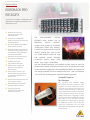
Congratulations! In purchasing our EURORACK PRO RX1202FX you have
acquired a mixing console whose small size belies its incredible versatility
and audio performance.
Table of Contents
Thank you ....................................................................... 2
Important Safety Instructions ...................................... 3
Legal Disclaimer ............................................................. 3
Limited warranty ............................................................ 3
1. Introduction ............................................................... 4
1.1 General mixing console functions ............................... 4
1.2 The user’s manual ............................................................... 5
1.3 Before you get started ...................................................... 5
2. Control Elements and Connectors .......................... 5
2.1 Mono channels .................................................................... 5
2.2 Stereo channels ................................................................... 6
2.3 Connector array of the main section ........................... 7
2.4 Main section ......................................................................... 8
2.5 Digital eects processor .................................................. 9
2.6 Voltage supply, phantom power supply
and fuse .......................................................................................... 9
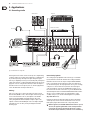
3. Applications ............................................................. 10
3.1 Recording studio ............................................................... 10
3.2 Live sound ........................................................................... 11
4. Installation ............................................................... 12
4.1 Mains connection ............................................................. 12
4.2 Audio connections ........................................................... 12
5. Specications ........................................................... 13
6. EURORACK PRO RX1202FX Eects Presets ............ 15

3 EURORACK PRO RX1202FX User Manual
Important Safety
Instructions
LEGAL DISCLAIMER
LIMITED WARRANTY
Terminals marked with this symbol carry
electrical current of su cient magnitude
to constitute risk of electric shock.
Use only high-quality professional speaker cables with
¼" TS or twist-locking plugs pre-installed. Allother
installation or modi cation should be performed only
by quali edpersonnel.
This symbol, wherever it appears,
alertsyou to the presence of uninsulated
dangerous voltage inside the
enclosure-voltage that may be su cient to constitute a
risk ofshock.
This symbol, wherever it appears,
alertsyou to important operating and
maintenance instructions in the
accompanying literature. Please read the manual.
Caution
To reduce the risk of electric shock, donot
remove the top cover (or the rear section).
No user serviceable parts inside. Refer servicing to
quali ed personnel.
Caution
To reduce the risk of re or electric shock,
do not expose this appliance to rain and
moisture. The apparatus shall not be exposed to dripping
or splashing liquids and no objects lled with liquids,
suchas vases, shall be placed on the apparatus.
Caution
These service instructions are for use
by quali ed service personnel only.
Toreduce the risk of electric shock do not perform any
servicing other than that contained in the operation
instructions. Repairs have to be performed by quali ed
servicepersonnel.
1. Read these instructions.
2. Keep these instructions.
3. Heed all warnings.
4. Follow all instructions.
5. Do not use this apparatus near water.
6. Clean only with dry cloth.
7. Do not block any ventilation openings. Install in
accordance with the manufacturer’s instructions.
8. Do not install near any heat sources such as
radiators, heat registers, stoves, or other apparatus
(including ampli ers) that produce heat.
9. Do not defeat the safety purpose of the polarized
or grounding-type plug. A polarized plug has two blades
with one wider than the other. A grounding-type plug
has two blades and a third grounding prong. The wide
blade or the third prong are provided for your safety. Ifthe
provided plug does not t into your outlet, consult an
electrician for replacement of the obsolete outlet.
10. Protect the power cord from being walked on or
pinched particularly at plugs, convenience receptacles,
and the point where they exit from the apparatus.
11. Use only attachments/accessories speci ed by
themanufacturer.
12. Use only with the
cart, stand, tripod, bracket,
or table speci ed by the
manufacturer, orsold with
the apparatus. When a cart
is used, use caution when
moving the cart/apparatus
combination to avoid
injury from tip-over.
13. Unplug this apparatus during lightning storms or
when unused for long periods of time.
14. Refer all servicing to quali ed service personnel.
Servicing is required when the apparatus has been
damaged in any way, such as power supply cord or plug
is damaged, liquid has been spilled or objects have fallen
into the apparatus, the apparatus has been exposed
to rain or moisture, does not operate normally, or has
beendropped.
15. The apparatus shall be connected to a MAINS socket
outlet with a protective earthing connection.
16. Where the MAINS plug or an appliance coupler is
used as the disconnect device, the disconnect device shall
remain readily operable.
17. Correct disposal of this
product: This symbol indicates
that this product must not be
disposed of with household
waste, according to the WEEE
Directive (2012/19/EU) and
your national law. This product
should be taken to a collection center licensed for the
recycling of waste electrical and electronic equipment
(EEE). The mishandling of this type of waste could have
a possible negative impact on the environment and
human health due to potentially hazardous substances
that are generally associated with EEE. At the same time,
your cooperation in the correct disposal of this product
will contribute to the e cient use of natural resources.
For more information about where you can take your
waste equipment for recycling, please contact your local
city o ce, or your household waste collection service.
18. Do not install in a con ned space, such as a book
case or similar unit.
19. Do not place naked ame sources, such as lighted
candles, on the apparatus.
20. Please keep the environmental aspects of battery
disposal in mind. Batteries must be disposed-of at a
battery collection point.
21. Use this apparatus in tropical and/or
moderate climates.
MUSIC Group accepts no liability for any loss
which may be su ered by any person who relies
either wholly or in part upon any description,
photograph, or statement contained herein.
Technical speci cations, appearances and other
information are subject to change without notice.
All trademarks are the property of their respective
owners. MIDAS, KLARK TEKNIK, LAB GRUPPEN, LAKE,
TANNOY, TURBOSOUND, TC ELECTRONIC, TC HELICON,
BEHRINGER, BUGERA and DDA are trademarks
or registered trademarks of MUSIC Group IP Ltd.
© MUSIC Group IP Ltd. 2016 All rights reserved.
For the applicable warranty terms and conditions
and additional information regarding MUSIC Group’s
Limited Warranty, please see complete details online at
music-group.com/warranty.

4 EURORACK PRO RX1202FX User Manual
1. Introduction
With 8 phantom-powered microphone inputs as well as 4 high-headroom line
inputs, the RX1202FX comprises a total of 12 channels. All channels come with
60-mm faders and the extremely musical 2-band EQ, the clip LEDs, as well
as the 2 aux sends enable an uncompromising functionality of the console.
An integrated power supply guarantees optimal exibility through worldwide
independence of any mains connection. Additionally, it oers an absolutely
noiseless audio signal as well as an outstanding transient response by minimal
power consumption. With rst-class “Invisible“ Mic Preamps, the ultra-low
noise circuitry, the 24-bit eects processor as well as the separate control room,
headphones and CD/tape outputs, the RX1202FX has all the features that also
distinguish our UB mixers.
As sub-mixer, monitor mixer or as line mixer for audio/video installations,
the RX1202FX is the rst choice for demanding xed installations and mobile use.
IMP “INVISIBLE” MIC PREAMP
The microphone channels are tted with BEHRINGER’s premium quality
IMP invisible mic preamps that boast the following features:
t 130 dB dynamic range for an incredible amount of headroom
t A bandwidth ranging from below 10 Hz to over 200 kHz for crystal-clear
reproduction of even the nest nuances
t The extremely low-noise and distortion-free circuitry gua rantees absolutely
natural and transparent signal repro duction
t They are perfectly matched to every conceivable micro phone with up to
60 dB gain and +48 volt phantom power supply
t They enable full utilization of the greatly extended dynamic range of your
24-bit/192 kHz HD recorder, thereby main taining optimal audio quality.
MULTI-EFFECTS PROCESSOR
In addition, the RX1202FX oers an eects processor equipped with 24-bit
A/D and D/A converters. The FX processor puts at your disposal 100 presets
with rst-class room simulations, delay and modulation eects, and many
multi-eects in outstanding audio quality.
Caution!
◊ We would like to inform you that high volume can damage your
hearing and/or the headphones or loudspeakers. Before turning on
the device, please move the MAIN MIX fader of the main section all
the way down. Always take care to keep an appropriate volume level.
1.1 General mixing console functions
A mixing console fulls three main functions:
t Signal processing:
Preamplication
Microphones convert sound waves into voltage that has to be amplied
several-fold; then, this voltage is turned into sound that is reproduced
in a loudspeaker. Because micro phone capsules are very delicate in their
construction, output voltage is very low and therefore susceptible to
interference. Therefore, mic signal voltage is amplied directly at the mixer
input to a higher signal level that is less prone to interference. This higher,
interference-safe signal level has to be achieved through amplication
using an amplier of the highest quality in order to amplify the signal
and add as little noise to it as possible. The IMP “Invisible” Mic Preamp
performs this role beautifully, leaving no traces of noise or sound coloration.
Interference that could take place at the preamplication level could aect
signal quality and purity, and would then be passed on to all other devices,
resulting in inaccurate sounding program during recording or playback.
Level-setting
Signals fed into the mixer using a DI box (Direct Injection) or the output of a
sound card or a keyboard, often have to be adjusted to the operating level of
your mixing console.
Frequency response correction
Using the equalizers found in each channel strip, you can simply,
quickly and eectively adjust the way a signal sounds.
t Signal distribution:
Individual, processed signals from the channel strips are compiled on busses
and are fed into the main section for further processing. Connections for
recording equipment, power ampliers, headphones as well as CD/tape
connectors are available here. The mix is sent to the internal FX processors or
external eects processors via aux sends and returns. Similarly, a mix can be
created for the musicians on the stage (monitor mix).
t Mix:
All other mixing console functions fall under this vital category. Creating a
mix means primarily adjusting the volume levels of individual instruments
and voices to one another as well as giving them the appropriate weight
within the overall frequency spectrum. Likewise, you’ll have to sensibly
spread individual voices across the stereo image of a signal. At the end of
this process, adjusting the level of the entire mix to other equipment in
the signal path is required (e. g. recorder/crossover/amplier).
The interface of BEHRINGER mixing consoles is optimized for these tasks,
enabling you to easily keep track of the signal path.

5 EURORACK PRO RX1202FX User Manual
1.2 The user’s manual
The user’s manual is designed to give you both an overview of the controls,
as well as detailed information on how to use them. In order to help you
understand the links between the controls, we have arranged them in groups
according to their function. If you need to know more about specic issues,
please visit our website at http://behringer.com. Additional information and
explanations about various music industry/audio technology terminology
can be found on individual product pages as well as in the glossary area
of behringer.com.
◊ The block diagram supplied with the mixing console gives you
an overview of the connections between the inputs and outputs,
as well as the associated switches and controls.
For the moment, just try and trace the signal path from the microphone input
to the FX SEND connector. Don’t be put o by the huge range of possibilities;
it’s easier than you think! If you look at the overview of the controls at the same
time, you’ll be able to quickly familiarize yourself with your mixing console and
you’ll soon be making the most of all its many possibilities.
1.3 Before you get started
1.3.1 Shipment
Your mixing console was carefully packed in the factory to guarantee safe
transport. Nevertheless, we recommend that you carefully examine the
packaging and its contents for any signs of physical damage that may
have occurred during transit.
◊ If the unit is damaged, please do NOT return it to us, but notify your
dealer and the shipping company immediately, otherwise claims for
damage or replacement may not be granted.
◊ To assure optimal protection of your EURORACK during use or transport,
we recommend utilizing a carrying case.
◊ Please always use the original packaging to avoid damage due
to storage or shipping.
◊ Never let unsupervised children play with the EURORACK or
with its packaging.
◊ Please dispose of all packaging materials in an
environmentally-friendly fashion.
1.3.2 Initial operation
Be sure that there is enough space around the unit for cooling purposes and to
avoid overheating please do not place your mixing console on high-temperature
equipment such as radiators or power amps.
◊ Never connect the EURORACK to the power supply unit when the latter
is connected to the mains! First connect the power supply unit to the
console, then connect the power supply unit to the mains.
◊ Please make sure that all units have a proper ground connection.
For your own safety, never remove or disable the ground
conductor from the unit or on the AC power cord. The unit should
always be connected to a mains socket outlet with a protective
earthing connection.
◊ When installing the product, ensure the appliance coupler or
power cord is easily accessible for disconnecting the unit from mains.
1.3.3 Online registration
Please register your new BEHRINGER equipment right after your purchase
by visiting http://behringer.com and read the terms and conditions of our
warranty carefully.
Should your BEHRINGER product malfunction, it is our intention to have it
repaired as quickly as possible. To arrange for warranty service, please contact
the BEHRINGER retailer from whom the equipment was purchased. Should your
BEHRINGER dealer not be located in your vicinity, you may directly contact
one of our subsidiaries. Corresponding contact information is included in
the original equipment packaging (Global Contact Information/European
Contact Information). Should your country not be listed, please contact the
distributor nearest you. A list of distributors can be found in the support area
of our website (http://behringer.com).
Registering your purchase and equipment with us helps us process your repair
claims more quickly and eciently.
Thank you for your cooperation!
2. Control Elements and Connectors
This chapter describes the various control elements of your mixing console.
All controls, switches and connectors will be discussed in detail.
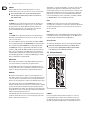
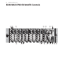
2.1 Mono channels
Fig. 2.1: Connectors and controls on the mono channels
MIC
Each mono input channel oers a balanced microphone input via the
XLR connector and also features a switchable +48 V phantom power supply
for condenser microphones.
◊ Please mute your playback system before you activate the
phantom power supply to prevent switch-on thumps being
directed to your loudspeakers. Please also note the instructions
in chapter 2.4 “Main section”.

6 EURORACK PRO RX1202FX User Manual
LINE IN
Each mono input also features a balanced line input on a ¼" connector.
Unbalanced devices (mono connectors) can also be connected to these inputs.
◊ Please remember that you can only use either the microphone
or the line input of a channel at any one time. You can never use
both simultaneously!
INSERT
The INSERT connector is input and output at the same time. This allows you
to insert external signal processors (compressors, gate, etc.) in the channel.
The signal retrieval occurs after the TRIM and is practically a diversion of
the signal. The input signal of the connected signal processor is diverted,
processed and led back to the channel for further processing.
TRIM
Use the TRIM control to adjust the input gain. This control should always be
turned fully counterclockwise whenever you connect or disconnect a signal
source to one of the inputs.
The scale has 2 dierent value ranges: the rst value range (+10 to +60 dB)
refers to the MIC input and shows the amplication for the signals fed in there.
The second value range (+10 to -40 dBu) refers to the line input and shows
its sensitivity. The settings for equipment with standard line-level signals
(-10 dBV or +4 dBu) look like this: While the TRIM control is turned all the way
down, connect your equipment. Set the TRIM control to the external devices’
standard output level. If that unit has an output signal level display, it should
show 0 dB during signal peaks. For +4dBu, turn up TRIM slightly, for -10 dBV a
bit more. Tweaking is done using the CLIP LED.
HIGH/LOW
All mono input channels include a 3-band equalizer. All bands provide boost
or cut of up to 15 dB. In the central position, the equalizer is inactive.
The upper (HIGH) and the lower band (LOW) are shelving lters that increase
or decrease all frequencies above or below their cut-o frequency. The cut-o
frequencies of the upper and lower band are 12 kHz and 80Hz respectively.
MON/FX
FX send buses (or AUX send buses) enable you to extract signals from one or
more channels and collect these on a bus. You can retrieve the signal at the send
connector to direct it to an external eects device, for example. The AUX return
input is used as the return path. The send buses of the RX1202FX are mono buses.
As the name suggests, the FX sends of the EURORACK mixing consoles are
intended to drive eects devices (reverb, delay, etc.) and are therefore congured
post-fader. This means that the mix between dry signal and eect remains at
the level determined by the channel’s aux send, irrespective of the channel fader
setting. If this were not the case, the eects signal of the channel would remain
audible even when the fader is lowered to zero.
In the RX1202FX, the FX send is routed directly to the built-in eects processor.
To make sure that the eects processor receives an input signal, you shouldn’t
turn this control all the way to the left (-∞).
The MON path—as the name already implies—is meant to be used as monitor
signal path. For this application, it is important that the controller works as
pre-fader, which means it does not rely on the fader position. For this reason the
AUX send path is unsuitable for the connection to eects devices. By using the
MON controller, you can produce a mono mix of individual signals that can be
routed over the MON plug, located on the backside, to a headphones amplier
(e.g. MINIAMP AMP800) or a power amplier for monitoring.
PAN
The PAN control determines the position of the channel signal within the
stereo image. This control features a constant-power characteristic, which means
the signal is always maintained at a constant level, irrespective of position in
the stereo panorama.
CLIP
The CLIP LEDs of the mono channels illuminate when the input signal is driven
too high, which could cause distortion. If this happens, use the TRIM control to
reduce the preamp level until the LED does not light anymore.
Channel fader
The channel fader determines the level of the channel signal in the Main Mix.
◊ Caution: The channel fader needs to be open so that the effects
processor receives a signal from this channel because the FX bus
to the effects processor is switched to post-fader!
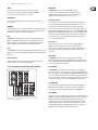
2.2 Stereo channels
Fig. 2.2: Connectors and controls on the stereo channels
LINE IN
Each stereo channel has two balanced line level inputs on ¼" connectors
for left and right channels. If only the connector marked “L” (left) is used,
the channel operates in mono. The stereo channels are designed to handle
typical line level signals. Both inputs will also accept unbalanced connectors.

7 EURORACK PRO RX1202FX User Manual
TRIM
The controller works the same as the one for the mono channels.
However, the level control range is limited from +20 to -20 dBu
because the stereo channels only process line signals.
HIGH/LOW
The stereo-channel equalizer features 2 bands like the one used for the
mono channels.
MON/FX
The MON/FX buses of the stereo channels work like those of the mono channels.
Since both paths are mono, the signal of a stereo channel is initially mixed to a
summed mono signal before reaching the MON/FX bus.
BAL
The BAL(ANCE) control determines the levels of left and right input signals
relative to each other before both signals are then routed to the main stereo
mix bus. If a channel is operated in mono via the left line input, this control
has the same function as the PAN control used in the mono channels.
CLIP
The CLIP LEDs of the stereo channels light up when the input signal’s level is too
high. In this case, reduce the preamplication with the TRIM controller until the
LED goes out.
Channel fader
As with the mono channels, the channel fader determines the level of the
channel strip for the stereo channels in the main mix.
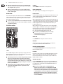
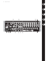
2.3 Connector array of the main section
Fig.2.3: Connectors of the main section
MAIN OUT
The MAIN OUT connectors are balanced and laid out as XLR
connectors. Here the summed signal of the main mix has a level of
0 dBu. According to the way you want to use the mixer and which
equipment you have, following devices can be connected:
Live PA systems:
A stereo dynamics processor (optional), stereo equalizer (optional) and the
stereo power amplier for full-range loudspeakers with passive crossovers.
If you wish to use multi-way loudspeaker systems without an integrated
crossover, you have to use an active crossover and several power ampliers.
Often, limiters are already built into active crossovers (e.g. BEHRINGER SUPER-X
PRO CX2310 and ULTRADRIVE PRO DCX2496). Active crossovers are implemented
directly before the power amplier, and they divide the frequency range into
several segments that are rst amplied in the ampliers and then passed on
to the corresponding loudspeakers.
Recording:
For mastering, using a stereo compressor such as the COMPOSER PRO-XL
MDX2600 can be recommended. Use it to custom-tailor the dynamic
characteristics of your signal to the dynamic range of the recording equipment
you are using. The signal is in this case passed on from the compressor into
the recorder.
CTRL OUT
The CTRL OUT connectors are used for controlling the summed signal
(eects mix and main mix) as well as for individual signals over studio monitor
speakers. By using the PHONES/CONTROL ROOM controller in the main section,
you can control the level of both outputs.
CD/TAPE IN
The CD/TAPE INs are used to bring an external signal source (e.g. CD player,
tape deck, etc.) into the console. They can also be used as a standard stereo line
input, so the output of a second EURORACK or BEHRINGER ULTRALINK PRO MX882
can be connected. Alternatively, the line or tape output of a hi- amplier with
source selection switch could also be hooked up here, allowing you to easily listen
to additional sources (e.g. cassette recorder, minidiskplayer, sound card etc.).
CD/TAPE OUT
These connections are laid out as RCA connectors and are wired parallel to
MAIN OUT. Connect the inputs of a computer sound card or a recorder here.
The output signal level is set up using the highly accurate MAIN MIX fader.
AUX SENDS
The FX connector routes the signal, which you have extracted from the individual
channels by using the FX controller; the MON plug does the same to the signal
that has been extracted by using the MON controller. Connect the input of
an external eects processor to the FX plug, with which you want to modify
the signal sum of the FX bus. Then, route the eects signal back to the mixer
over the AUX RETURN connectors. With the MON outputs, you can connect an
amplier/headphones amplier for the musicians to monitor.

8 EURORACK PRO RX1202FX User Manual
◊ When the connected effects device does not receive an input signal,
none of the FX controllers are probably turned up, which also applies
to the integrated effects -processor.
◊ Adjust your external effects processor to 100% wet (effects signal
only), because the effects signal is added to the main mix along with
the “dry” channel signals.
AUX RETURN
You can connect the outputs of an external eects device to the AUX RETURN
connectors. In this case, the eects signal is routed directly to the main mix bus
and is then mixed with the “dry” signal. It is also possible to route the eects
signal as mono by using the L connector.
◊ You can also use the AUX RETURN connectors as additional stereo input
channels, although, in this case, there are no possibilities to control the
level, timbre and panning.
2.4 Main section
Fig. 2.4: Control elements of the main section
+48 V
The red “+48 V”-LED lights up when the phantom power supply is switched on.
Phantom powering is necessary to use condenser microphones and is activated
with the PHANTOM ON switch found on the backside.
◊ Connect microphones before you switch on the phantom power supply.
Please do not connect microphones to the mixer (or the stagebox/
wallbox) while the phantom power supply is switched on. In addition,
the monitor/PA loud speakers should be muted before you activate the
phantom power supply. After switching on, wait approx. one minute to
allow for system stabilization.
◊ Caution! You must never use unbalanced XLR connectors (PIN 1 and
3 connected) on the MIC input connectors if you want to use the
phantom power supply.
POWER
The blue POWER LED indicates that the console is powered on.
LEVEL INDICATOR
The 4-segment display accurately displays the relevant signal level.
Level Control:
To level the signal, you should set the channel fader of the input channels to 0 dB
and raise the input amplication with the TRIM controller to the extent that a
level of maximal 0 dB is displayed.
When recording to digital recorders, the recorder’s peak meter should not go into
overload. While analog recorders can be overloaded to some extent, creating only
a certain amount of distortion, digital recorders distort quickly when overloaded.
In addition, digital distortion is not only undesirable, but also renders your
recording completely useless.
When recording to an analog device, the VU meters of the recording machine
should reach approx. +3 dB with low-frequency signals (e.g. kick drum). Due to
their inertia VU meters tend to display too low a signal level at frequencies
above 1 kHz. This is why, for example, a Hi-Hat should only be driven as
far as -10 dB. Snaredrums should be driven to approx. 0 dB.
◊ The CLIP LEDs of your EURORACK display the level virtually
independent of frequency. A recording level of 0 dB is
recommended for all signal types.
MAIN MIX
Use the MAIN MIX fader to adjust the volume of the main out.
PHONES
The connector is used to connect a pair of headphones. The volume level
is changed with the PHONES/CONTROL ROOM controller.
PHONES/CONTROL ROOM
Use the PHONES/CONTROL ROOM control to adjust the signal level of the
CTRL OUT and PHONES outputs.
FX SOLO
If you want to only listen to the eects signal with your headphones or monitor
speakers, then press the FX SOLO switch. The signal of the eects device can
then be heard individually; the main mix or CD/tape signal is inaudible at the
PHONES and CTRL OUT outputs.
CD/TAPE TO CTRL
Press the CD/TAPE TO CTRL switch if you want to monitor the CD/TAPE IN via
the CTRL OUT and PHONES outputs. A typical studio application of this function
is recording music into a digital audio workstation (DAW) with simultaneous
reproduction (see ch. 3.1).
◊ When you are recording a signal over the CD/TAPE OUT and
simultaneously want to monitor over the CD/TAPE IN, the CD/TAPE
TO MIX switch is not allowed to be pressed. Otherwise a feedback loop
would occur because this signal would be sent over the Main Mix back
to the CD/TAPE OUT. In case of such an application, you should send the
CD/TAPE signal to the monitor speakers or headphones by using the
CD/TAPE TO CTRL switch. In contrast to the main mix, this signal is not
sent to the CD/TAPE OUT.

9 EURORACK PRO RX1202FX User Manual
CD/TAPE TO MIX
When the CD/TAPE TO MIX switch is pressed, the CD/tape input is assigned to
the main mix providing an additional input for tape machines, MIDI instruments
or other signal sources that do not require any processing.
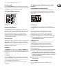
2.5 Digital eects processor
Fig. 2.5: Eects section
100 FIRST-CLASS EFFECTS
The EURORACK RX1202FX features a built-in digital stereo eects processor.
This eects processor oers a large number of standard eects such as Hall,
Chorus, Flanger, Delay and various combination eects. Using the FX control,
you can feed signals into the eects processor. The integrated eects
module has the advantage of requiring no wiring. This way, the danger of
creating ground loops or uneven signal levels is eliminated at the outset,
completely simplifying the handling.
SIG and CLIP LED
The SIG LED on the eects module shows the presence of a signal whose level
is high enough. This LED should always be on. However, make sure that the
CLIP LED lights up only sporadically. If it is lit constantly, you are overdriving
the eects processor, which leads to unpleasant distortion. If this occurs,
turn the FX controls down somewhat.
PROGRAM
The PROGRAM control has two functions: by turning the PROGRAM control,
you dial the number of an eect. The number of the preset you just dialed up
blinks in the display. To conrm your selection, press the PROGRAM control;
the blinking stops.
FX TO MAIN
By using the FX TO MAIN controller, the eects signal is sent to the main mix.
No eects signal is to be heard in the summed signal of the mixer when the
controller is positioned entirely to the left. Choose this position if you want to
use an external eects device for the FX output.
An overview of all the multieect processor’s presets are to be found in
the appendix.
2.6 Voltage supply, phantom power supply
and fuse
FUSE HOLDER/IEC MAINS RECEPTACLE
The mains connection is made via a cable with an IEC mains connector and
meets the required safety standards. An appropriate mains cable is supplied
with the equipment. Blown fuses must only be replaced by fuses of the same
type and rating.
Fig. 2.6: Voltage supply and fuse
POWER switch
Use the POWER switch to turn on the mixing console. The POWER switch
should always be in the “O” position when you are about to connect your unit
to the mains.
To disconnect the unit from the mains, pull out the main cord plug.
When installing the product, ensure that the plug is easily accessible.
If mounting in a rack, ensure that the mains can be easily disconnected
by a plug pull or by an all-pole disconnect switch on or near the rack.
◊ Attention: The POWER switch does not fully disconnect the unit from
the mains. Unplug the power cord completely when the unit is not
used for prolonged periods of time.
PHANTOM switch
The PHANTOM switch activates the phantom power (necessary to operate
condenser microphones) on the XLR sockets of the mono channels.
The red +48 V LED illuminates when phantom power is on. As a rule,
dynamic microphones can still be used with phantom power, provided that
they are wired in a balanced conguration. In case of doubt, contact the
microphone manufacturer!
◊ Connect microphones before you switch on the phantom power supply.
Please do not connect microphones to the mixer (or the stagebox/
wallbox) while the phantom power supply is switched on. In addition,
the monitor/PA loud-speakers should be muted before you activate the
phantom power supply. After switching on, wait approx. one minute to
allow for system stabilization.
◊ Caution! Please also note the information given in chapter 4.2
“Audio connections”.
SERIAL NUMBER
Please note the important information on the serial number given in
chapter 1.3.3.

10 EURORACK PRO RX1202FX User Manual
3. Applications
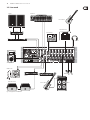
3.1 Recording studio
MIDI sound module
B-2 Pro
V-Amp 3
Electric Guitar
HPS3000
HPS3000
TRUTH B200A
Keyboard
F-Control FCA202
Laptop
MD Recorder
Mini Amp Amp 800
Fig. 3.1: The RX1202FX in a recording studio
Even though most of the tasks in a studio can nowadays be accomplished using
a computer, a mixing console remains an unavoidable piece of equipment that
lets you eectively manage audio inputs and outputs: microphone signals
need to be pre-amplied prior to being recorded, and the quality of microphone
sound is often worked on; recording and playback signals must be routed to the
appropriate connectors or integrated into the mix; the volume of headphones
and studio monitors needs to be adjusted, and so on. The well-equipped main
section of the RX1202FX is extremely useful in this case.
Cabling:
Connect your sound sources to the mic or line inputs of the mixer. Join your
master machine (DAT/MD recorder) to the main outputs. Your monitor speaker
is connected to the CTRL OUT connector, the headphones to the PHONES
output. Now attach the CD/TAPE outputs with the inputs of the sound
card of your Digital Audio Workstation (DAW). Hook up the outputs of the
computer’s soundcard to the CD/TAPE inputs. Connect a headphone amplier
to the MON connector to be able to provide performing musicians with a
monitoring signal.
Record and playback:
The recording signal is preamplied in a mixer’s channel, processed with the
EQ and routed back to the main bus. Determine the recording level with the
LEVEL fader. The entire level to the computer is adjusted with the MAIN MIX
fader. To ensure that the signal is really being recorded, you should not listen
in to the main mix signal (i.e. the output signal of the console, prior to recording)
of the phones or control room bus. Instead, listen in to the returned signal
of the soundcard that is connected to the CD/TAPE inputs, in which case you
have a kind of read-after-write control. In this case, press the CD/TAPE TO CTRL
switch and adjust the volume level with the PHONES/CONTROL ROOM controller.
This way you can record further tracks to an existing playback (so-called
overdubs). In the process, use the Direct Monitoring function of your DAW
(Digital Audio Workstation).
Determine the amount of the input signals (keyboard, guitar, sound module
and microphone) in the mono and stereo channels that are to be sent to the
MON output by using the MON controller of the corresponding channel.
◊ With this application, the CD/TAPE TO MIX switch should not be pressed;
otherwise, the playback signal from the sound card output would be
routed back to the computer and would be added to the recording.
This would not only be undesirable, it would also create a feedback loop.

11 EURORACK PRO RX1202FX User Manual
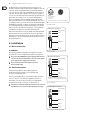
3.2 Live sound
MD Recorder
VP1520
COMPOSER PRO-XL MDX2600
EP2000
CD Player
EP2000 VIRTUALIZER 3D FX2000
EUROLIVE F1220A
Electric Guitar
HPS3000
Keyboard
Electric Bass
BX4500H
BB410
VIRTUE VT250FX
Drum Machine
XM8500
Fig. 3.2: Live application of the RX1202FX

12 EURORACK PRO RX1202FX User Manual
This illustration shows a typical arrangement for a live setup. Two vocal
microphones and the line outputs of a guitar and a bass amplier are connected
to the mono channels of the RX1202FX. A keyboard and a drum computer are
connected to the stereo channels. The power amplier in your sound system is
connected to the main outputs; equipment such as compressors, equalizers or
crossovers are located between the mixer and the amp in the signal path. If you
wish to make a live recording, you can connect your recording equipment
(in this case, a minidisk recorder) to the CD/TAPE outputs. A CD player that is
playing during intermissions is connected via the CD/TAPE inputs. If you connect
a recorder/player combo (e. g. a tape deck recorder), the CD/TAPE TO MIX switch
should not be pressed during a recording because this way the signal intended
for recording would be directly re-routed back to the mixing console, and then
back to the recorder... this would cause a feedback loop as soon as you hit the
record button. A loud, unpleasant, even painful sound would result.
Connect two monitor speakers over a power amplier to the MON output which
musicians can then use on stage. Determine the amount of the input signals
(microphone, bass, keyboard, drum computer and guitar) in the mono and stereo
channels that are to be sent to the MON output by using the MON controller of
the corresponding channel.
4. Installation
4.1 Mains connection
AC POWER IN
The power supply is delivered through the power supply line to be found on
the backside. The connection complies with the required security regulations.
◊ Never connect the EURORACK to the power supply line while the latter
is already connected to the mains! Rather connect the console with the
power supply line before plugging it into the mains.
◊ Please note that the mixer warms up when in operation.
This is absolutely normal.
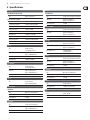
4.2 Audio connections
You will need a large number of cables for dierent applications.
The illustrations below show how the connectors should be wired.
Be sure to use only high-grade cables.
Please use commercial RCA cables to connect the CD/tape inputs and outputs.
You can, of course, also connect unbalanced equipment to the balanced
inputs/outputs. To do this, use either mono plugs or stereo plugs with the
ring and sleeve bridged (pins 1 and 3 in the case of XLR connectors).
◊ Caution! Never use unbalanced XLR connectors (PIN 1 and 3 connected)
on the MIC input connectors when using the phantom power supply.
For unbalanced use, pin 1 and pin 3 have to be bridged
1 = ground/shield
2 = hot (+ve)
3 = cold (-ve)
input
12
3
output
1
2
3
Fig. 4.1: XLR connections
strain relief clamp
sleeve
tip
sleeve
(ground/shield)
Unbalanced ¼" TS connector
tip
(signal)
Fig. 4.2: ¼" mono plug
strain relief clamp
sleeve
ring
tip
sleeve
ground/shield
For connection of balanced and unbalanced plugs,
ring and sleeve have to be bridged at the stereo plug.
Balanced ¼" TRS connector
ring
cold (-ve)
tip
hot (+ve)
Fig. 4.3: ¼" stereo plug
strain relief clamp
sleeve
ring
tip
sleeve
ground/shield
¼" TRS headphones connector
ring
right signal
tip
left signal
Fig. 4.4: Stereo plug for headphones connection

13 EURORACK PRO RX1202FX User Manual
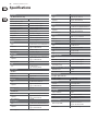
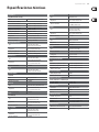
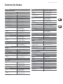
5. Specications
Mono Inputs
MIC (IMP Invisible Mic Preamp)
Type XLR, electr. balanced
Mic E.I.N. (20 Hz – 20 kHz)
@ 0 Ω source resistance -132 dB / -134 dB A-weighted
@ 50 Ω source resistance -130 dB / -132 dB A-weighted
@ 150 Ω source resistance -128 dB / -130 dB A-weighted
Frequency response <10 Hz – 200 kHz
Gain range +10 to +60 dB
Max. input level +12 dBu @ +10 dB gain
Impedance approx. 2.6 kΩ balanced
Signal-to-noise ratio -110 dB / -112 dB A-weighted
Distortion (THD+N) 0.003%, A-weighted
Line In
Type ¼" TRS connector,
electronically balanced
Impedance approx. 20 kΩ balanced
approx. 10 kΩ unbalanced
Gain range -10 dB to +40 dB
Max. input level +22 dBu @ 0 dB gain
Stereo Inputs
Type ¼" TRS connector,
electronically balanced
Impedance approx. 20 kΩ balanced
approx. 10 kΩ unbalanced
Max. input level +22 dBu
Insert
Type ¼" TRS connector
(Tip=Send, Ring=Return)
Auxiliary Inputs
CD/TAPE IN
Type RCA connectors, unbalanced
Impedance approx. 20 kΩ
Max. input level +22 dBu
Aux Return
Type ¼" TRS connector, balanced
Impedance approx. 20 kΩ balanced
approx. 10 kΩ unbalanced
Max. input level +22 dBu
Outputs
AUX SENDS (FX)
Type ¼" TRS connector, impedance balanced
Impedance approx. 240 Ω balanced
approx. 120 Ω unbalanced
Max. output level +22 dBu
Aux Sends (MON)
Type ¼" TRS connector, impedance balanced
Impedance approx. 240 Ω balanced
approx. 120 Ω unbalanced
Max. output level +22 dBu
Main Out
Type XLR connectors, balanced
Impedance approx. 240 Ω balanced
approx. 120 Ω unbalanced
Max. output level +28 dBu balanced
+22 dBu unbalanced
Ctrl Out
Type ¼" TRS connector, impedance balanced
Impedance approx. 240 Ω balanced
approx. 120 Ω unbalanced
Max. output level +22 dBu
CD/Tape Out
Type RCA connectors, unbalanced
Impedance approx. 1 kΩ
Max. output level +22 dBu
Phones
Type ¼" TRS connector
Max. output level +19 dBu / 150 Ω (316 mW)
EQ
Low 100 Hz / ±15 dB
High 12 kHz / ±15 dB

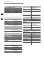
14 EURORACK PRO RX1202FX User Manual
Main Mix System Data
1
Noise
Main mix @ -∞, -98 dB / -101 dB A-weighted
Channel fader -∞
Main mix @ 0 dB, -85 dB / -88 dB A-weighted
Channel fader -∞
Main mix @ 0 dB, -77 dB / -80 dB A-weighted
Channel fader @ 0 dB
Fade Attenuation
2
(Crosstalk attenuation)
Main fader closed 90 dB
Channel fader closed 90 dB
Frequency Response
Microphone input to Main Out
<20 Hz – 105 kHz +1 dB / -1 dB
<10 Hz – 170 kHz +3 dB / -3 dB
Eects Section
Converter 24-bit Sigma-Delta
Frequency rate 40 kHz
Presets 100
Power Supply
Power consumption 18 W
Voltage 100 – 240 V~, 50/60 Hz
Fuse 100 – 240 V~: T 1.6 A H 250 V
Mains connection IEC (power) cable
Dimensions/Weight
Dimensions (H x W x D) approx. 133 x 482 x 150 mm
approx. (5.2 x 19 x 6")
Weight (net) approx. 3.04 kg (6.7 lbs)
Measuring conditions:
1: 20 Hz – 20 kHz; measured at main output. Channels1 – 8 gain @ unity; EQ flat; all channels on main mix;
channels 1/3/5/7 leftmost, channels 2/4/6/8 rightmost. Reference = +6 dBu.
2: 1 kHz relative to 0 dBu; 20 Hz – 20 kHz; line input; main output; gain @ unity.

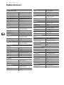
15 EURORACK PRO RX1202FX User Manual
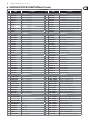
6. EURORACK PRO RX1202FX Eects Presets
EFFECTS PRESETS
No. EFFECT Description No. EFFECT Description
HALL 00-09 DELAY 50-59
00 SMALL HALL 1 approx. 1.0s reverb decay 50 SHORT DELAY 1 Like a short shattering
01 SMALL HALL 2 approx. 1.2s reverb decay 51 SHORT DELAY 2 1-2 short impulse(s)
02 SMALL HALL 3 approx. 1.5s reverb decay 52 SHORT DELAY 3 1-2 short impulse(s)
03 MID HALL 1 approx. 1.8s reverb decay 53 MID DELAY 1 Classical Delay for up-tempo music (115-125 BPM)
04 MID HALL 2 approx. 2.0s reverb decay 54 MID DELAY 2 Classical Delay for mid-tempo music (105-115 BPM)
05 MID HALL 3 approx. 2.5s reverb decay 55 MID DELAY 3 Classical Delay for slow-tempo music (95-105 BPM)
06 BIG HALL 1 approx. 2.8s reverb decay 56 LONG DELAY 1 Classical Delay for reggae-tempo music (85-95 BPM)
07 BIG HALL 2 approx. 3.2s reverb decay 57 LONG DELAY 2 Classical Delay for dub-tempo music (75-85 BPM)
08 BIG HALL 3 approx. 4s reverb decay 58 LONG DELAY 3 Extra long (nearly innite) delay eect
09 CHURCH approx. 7 s reverb decay 59 LONG ECHO Extra long canyon echo eect
ROOM 10-19 CHORUS 60-69
10 SMALL ROOM 1 approx. 0.5s reverb decay 60 SOFT CHORUS 1 Unobtrusive eect
11 SMALL ROOM 2 approx. 0.8s reverb decay 61 SOFT CHORUS 2 Unobtrusive eect with dierent color
12 SMALL ROOM 3 approx. 1.0s reverb decay 62 WARM CHORUS 1 Analog sounding
13 MID ROOM 1 approx. 1.2s reverb decay 63 WARM CHORUS 2 Analog sounding with dierent color
14 MID ROOM 2 approx. 1.5s reverb decay 64 PHAT CHORUS 1 Pronounced chorus eect
15 MID ROOM 3 approx. 1.8s reverb decay 65 PHAT CHORUS 2 Pronounced chorus eect with dierent color
16 BIG ROOM 1 approx. 2.0s reverb decay 66 CLASSIC FLANGER Standard anger eect
17 BIG ROOM 2 approx. 2.2s reverb decay 67 WARM FLANGER More analog touch
18 BIG ROOM 3 approx. 1.5s reverb decay 68 DEEP FLANGER Deep modulation impression
19 CHAPEL approx. 3s reverb decay 69 HEAVY FLANGER Extremely pronounced eect
PLATE 20-29 PHASE/PITCH 70-79
20 SHORT PLATE approx. 1.0s reverb decay 70 CLASSIC PHASER Standard phaser eect
21 MID PLATE approx. 1.5s reverb decay 71 WARM PHASER More analog touch
22 LONG PLATE approx. 2.2s reverb decay 72 DEEP PHASER Deep modulation impression
23 VOCAL PLATE approx. 1.2s reverb decay 73 HEAVY PHASER Extreme strong eect
24 DRUMS PLATE approx. 1.0s reverb decay 74 PITCH SHIFT DETUNE 2-3 times detune for a wider solo voice sound
25 GOLD PLATE 1 approx. 1.2s reverb decay 75 PITCH SHIFT +3 Minor third added voice
26 GOLD PLATE 2 approx. 2.0s reverb decay 76 PITCH SHIFT +4 Major third added voice
27 SHORT SPRING approx. 1.0s reverb decay 77 PITCH SHIFT +7 Quint above added voice
28 MID SPRING approx. 2.0s reverb decay 78 PITCH SHIFT -5 Fourth down added voice
29 LONG SPRING approx. 2.5s reverb decay 79 PITCH SHIFT -12 1 octave down added voice
GATED/REVERSE 30-39 MULTI 1 80-89
30 GATED REV SHORT approx. 0.8s reverb decay 80 CHORUS + REVERB 1 Soft chorus + medium-short reverb
31 GATED REV MID approx. 1.2s reverb decay 81 CHORUS + REVERB 2 Deep chorus + medium-long reverb
32 GATED REV LONG approx. 2.0s reverb decay 82 FLANGER + REVERB 1 Soft anger + medium-short reverb
33 GATED REV XXL approx.3.0s reverb decay 83 FLANGER + REVERB 2 Deep anger + medium-long reverb
34 GATED REV DRUM 1 approx. 0.8s reverb decay 84 PHASER + REVERB 1 Soft phaser + medium-short reverb
35 GATED REV DRUM 2 approx. 1.2s reverb decay 85 PHASER + REVERB 2 Deep phaser + medium-long reverb
36 REVERSE SHORT approx. 0.8s reverb decay 86 PITCH + REVERB 1 Soft voice detuning + medium-short reverb
37 REVERSE MID approx. 1.2s reverb decay 87 PITCH + REVERB 2 Fourth above interval + medium-long reverb
38 REVERSE LONG approx. 2.0s reverb decay 88 DELAY + REVERB 1 Short delay +medium-short reverb
39 REVERSE XXL approx. 3.0s reverb decay 89 DELAY + REVERB 2 Medium-long delay +medium-long reverb
EARLY REFLECTIONS 40-49 MULTI 2 80-89
40 EARLY REFLECTIONS 1 Short 90 DELAY + GATED REV Short delay + medium-long gated reverb
41 EARLY REFLECTIONS 2 Medium-short 91 DELAY + REVERSE Medium-short delay + medium-long reverse reverb
42 EARLY REFLECTIONS 3 Medium-long 92 DELAY + CHORUS 1 Short delay + soft chorus
43 EARLY REFLECTIONS 4 Long 93 DELAY + CHORUS 2 Medium-long delay + deep chorus
44 SHORT AMBIENCE Short 94 DELAY + FLANGER 1 Short delay + soft anger
45 MID AMBIENCE Medium-short 95 DELAY + FLANGER 2 Medium-long delay + deep anger
46 LIVE AMBIENCE Medium-short 96 DELAY + PHASER 1 Short delay + soft phaser
47 BIG AMBIENCE Medium-long 97 DELAY + PHASER 2 Medium-long delay + deep phaser
48 STADIUM Long 98 DELAY + PITCH 1 Short delay + fourth down interval
49 GHOST AMBIENCE Extra-long special FX 99 DELAY + PITCH 2 Medium-long delay + minor third above interval

16 EURORACK PRO RX1202FX User Manual
FEDERAL COMMUNICATIONS
COMMISSION COMPLIANCE
INFORMATION
Responsible Party Name: MUSIC Group Services NV Inc.
Address: 5270 Procyon Street
Las Vegas, NV 89118
USA
Phone Number: +1 702 800 8290
EURORACK PRO RX1202FX
complies with the FCC rules as mentioned in the followingparagraph:
This equipment has been tested and found to comply with the limits for a ClassB
digital device, pursuant to part 15 of the FCC Rules. These limits are designed
to provide reasonable protection against harmful interference in a residential
installation. This equipment generates, uses and can radiate radio frequency
energy and, if not installed and used in accordance with the instructions, may cause
harmful interference to radio communications. However, there is no guarantee that
interference will not occur in a particular installation. If this equipment does cause
harmful interference to radio or television reception, which can be determined
by turning the equipment o and on, the user is encouraged to try to correct the
interference by one or more of the followingmeasures:
t Reorient or relocate the receiving antenna.
t Increase the separation between the equipment and receiver.
t Connect the equipment into an outlet on a circuit dierent from that to which the
receiver is connected.
t Consult the dealer or an experienced radio/TV technician forhelp.
This device complies with Part 15 of the FCC rules. Operation is subject to the
following two conditions:
(1) this device may not cause harmful interference, and
(2) this device must accept any interference received, including interference that may
cause undesired operation.
Important information:
Changes or modications to the equipment not expressly approved by MUSIC Group
can void the user’s authority to use the equipment.
EURORACK PRO RX1202FX

Dedicate Your Life to Music

(Check out behringer.com for Full Manual)
Quick Start Guide
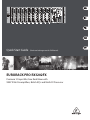
EURORACK PRO RX1202FX
Premium 12-Input Mic/Line Rack Mixer with
XENYX Mic Preampliers, British EQ's and Multi-FX Processor

2 EURORACK PRO RX1202FX
Important Safety
Instructions
LEGAL DISCLAIMER
LIMITED WARRANTY
Terminals marked with this symbol carry
electrical current of su cient magnitude
to constitute risk of electric shock.
Use only high-quality professional speaker cables with
¼" TS or twist-locking plugs pre-installed. Allother
installation or modi cation should be performed only
by quali edpersonnel.
This symbol, wherever it appears,
alertsyou to the presence of uninsulated
dangerous voltage inside the
enclosure-voltage that may be su cient to constitute a
risk ofshock.
This symbol, wherever it appears,
alertsyou to important operating and
maintenance instructions in the
accompanying literature. Please read the manual.
Caution
To reduce the risk of electric shock, donot
remove the top cover (or the rear section).
No user serviceable parts inside. Refer servicing to
quali ed personnel.
Caution
To reduce the risk of re or electric shock,
do not expose this appliance to rain and
moisture. The apparatus shall not be exposed to dripping
or splashing liquids and no objects lled with liquids,
suchas vases, shall be placed on the apparatus.
Caution
These service instructions are for use
by quali ed service personnel only.
Toreduce the risk of electric shock do not perform any
servicing other than that contained in the operation
instructions. Repairs have to be performed by quali ed
servicepersonnel.
1. Read these instructions.
2. Keep these instructions.
3. Heed all warnings.
4. Follow all instructions.
5. Do not use this apparatus near water.
6. Clean only with dry cloth.
7. Do not block any ventilation openings. Install in
accordance with the manufacturer’s instructions.
8. Do not install near any heat sources such as
radiators, heat registers, stoves, or other apparatus
(including ampli ers) that produce heat.
9. Do not defeat the safety purpose of the polarized
or grounding-type plug. A polarized plug has two blades
with one wider than the other. A grounding-type plug
has two blades and a third grounding prong. The wide
blade or the third prong are provided for your safety. Ifthe
provided plug does not t into your outlet, consult an
electrician for replacement of the obsolete outlet.
10. Protect the power cord from being walked on or
pinched particularly at plugs, convenience receptacles,
and the point where they exit from the apparatus.
11. Use only attachments/accessories speci ed by
themanufacturer.
12. Use only with the
cart, stand, tripod, bracket,
or table speci ed by the
manufacturer, orsold with
the apparatus. When a cart
is used, use caution when
moving the cart/apparatus
combination to avoid
injury from tip-over.
13. Unplug this apparatus during lightning storms or
when unused for long periods of time.
14. Refer all servicing to quali ed service personnel.
Servicing is required when the apparatus has been
damaged in any way, such as power supply cord or plug
is damaged, liquid has been spilled or objects have fallen
into the apparatus, the apparatus has been exposed
to rain or moisture, does not operate normally, or has
beendropped.
15. The apparatus shall be connected to a MAINS socket
outlet with a protective earthing connection.
16. Where the MAINS plug or an appliance coupler is
used as the disconnect device, the disconnect device shall
remain readily operable.
TECHNICAL SPECIFICATIONS AND APPEARANCES
ARE SUBJECT TO CHANGE WITHOUT NOTICE AND
ACCURACY IS NOT GUARANTEED. BEHRINGER,
KLARKTEKNIK, MIDAS, BUGERA, AND TURBOSOUND
ARE PART OF THE MUSIC GROUP MUSICGROUP.COM.
ALL TRADEMARKS ARE THE PROPERTY OF THEIR
RESPECTIVE OWNERS. MUSICGROUP ACCEPTS NO
LIABILITY FOR ANY LOSS WHICH MAY BE SUFFERED
BY ANY PERSON WHO RELIES EITHER WHOLLY OR
IN PART UPON ANY DESCRIPTION, PHOTOGRAPH
OR STATEMENT CONTAINED HEREIN. COLORS AND
SPECIFICATIONS MAY VARY FROM ACTUAL PRODUCT.
MUSIC GROUP PRODUCTS ARE SOLD THROUGH
AUTHORIZED FULLFILLERS AND RESELLERS ONLY.
FULLFILLERSAND RESELLERS ARE NOT AGENTS OF
MUSICGROUP AND HAVE ABSOLUTELY NO AUTHORITY
TO BIND MUSICGROUP BY ANY EXPRESS OR IMPLIED
UNDERTAKING OR REPRESENTATION. THIS MANUAL
IS COPYRIGHTED. NO PART OF THIS MANUAL MAY
BE REPRODUCED OR TRANSMITTED IN ANY FORM
OR BY ANY MEANS, ELECTRONIC OR MECHANICAL,
INCLUDING PHOTOCOPYING AND RECORDING OF ANY
KIND, FOR ANY PURPOSE, WITHOUT THE EXPRESS
WRITTEN PERMISSION OF MUSICGROUPIPLTD.
ALL RIGHTS RESERVED.
© 2013 MUSICGroupIPLtd.
Trident Chambers, Wickhams Cay, P.O. Box 146,
Road Town, Tortola, British Virgin Islands
For the applicable warranty terms and conditions
and additional information regarding MUSIC Group’s
Limited Warranty, please see complete details online at
www.music-group.com/warranty.

Quick Start Guide 3
Instrucciones de
seguridad
NEGACIÓN LEGAL
GARANTÍA LIMITADA
Las terminales marcadas con este símbolo
transportan corriente eléctrica de
magnitud su ciente como para constituir
un riesgo de descarga eléctrica. Utilice solo cables de
altavoz profesionales y de alta calidad con conectores
TS de 6,3 mm o de bayoneta pre jados. Cualquier otra
instalación o modi cación debe ser realizada únicamente
por un técnico cuali cado.
Este símbolo, siempre que aparece,
leadvierte de la presencia de voltaje
peligroso sin aislar dentro de la caja;
estevoltaje puede ser su ciente para constituir un riesgo
dedescarga.
Este símbolo, siempre que aparece,
leadvierte sobre instrucciones operativas
y de mantenimiento que aparecen en la
documentación adjunta. Por favor, lea el manual.
Atención
Para reducir el riesgo de descarga
eléctrica, no quite la tapa (o la parte
posterior). No hay piezas en el interior del equipo que
puedan ser reparadas por el usuario. Si es necesario,
póngase en contacto con personal cuali cado.
Atención
Para reducir el riesgo de incendio o
descarga eléctrica, no exponga este
aparato a la lluvia, humedad o alguna otra fuente que
pueda salpicar o derramar algún líquido sobre el aparato.
Nocoloque ningún tipo de recipiente para líquidos sobre
el aparato.
Atención
Las instrucciones de servicio deben
llevarlas a cabo exclusivamente personal
cuali cado. Para evitar el riesgo de una descarga eléctrica,
no realice reparaciones que no se encuentren descritas
en el manual de operaciones. Lasreparaciones deben ser
realizadas exclusivamente por personalcuali cado.
1. Lea las instrucciones.
2. Conserve estas instrucciones.
3. Preste atención a todas las advertencias.
4. Siga todas las instrucciones.
5. No use este aparato cerca del agua.
6. Limpie este aparato con un paño seco.
7. No bloquee las aberturas de ventilación. Instale el
equipo de acuerdo con las instrucciones del fabricante.
8. No instale este equipo cerca de fuentes de calor
tales como radiadores, acumuladores de calor, estufas u
otros aparatos (incluyendo ampli cadores) que puedan
producir calor.
9. No elimine o deshabilite nunca la conexión a tierra
del aparato o del cable de alimentación de corriente.
Unenchufe polarizado tiene dos polos, uno de los cuales
tiene un contacto más ancho que el otro. Una clavija con
puesta a tierra dispone de tres contactos: dos polos y la
puesta a tierra. El contacto ancho y el tercer contacto,
respectivamente, son los que garantizan una mayor
seguridad. Si el enchufe suministrado con el equipo no
concuerda con la toma de corriente, consulte con un
electricista para cambiar la toma de corriente obsoleta.
10. Coloque el cable de suministro de energía de manera
que no pueda ser pisado y que esté protegido de objetos
a lados. Asegúrese de que el cable de suministro de
energía esté protegido, especialmente en la zona de la
clavija y en el punto donde sale del aparato.
11. Use únicamente los dispositivos o accesorios
especi cados por el fabricante.
12. Use únicamente la
carretilla, plataforma,
trípode, soporte o mesa
especi cados por el
fabricante o suministrados
junto con el equipo.
Altransportar el equipo,
tenga cuidado para evitar
daños y caídas al tropezar con algún obstáculo.
13. Desenchufe el equipo durante tormentas o si no va a
utilizarlo durante un periodo largo.
14. Confíe las reparaciones únicamente a servicios
técnicos cuali cados. La unidad requiere mantenimiento
siempre que haya sufrido algún daño, si el cable de
suministro de energía o el enchufe presentaran daños,
sehubiera derramado un líquido o hubieran caído objetos
dentro del equipo, si el aparato hubiera estado expuesto
a la humedad o la lluvia, si ha dejado de funcionar de
manera normal o si ha sufrido algún golpe o caída.
15. Al conectar la unidad a la toma de corriente eléctrica
asegúrese de que la conexión disponga de una unión
atierra.
16. Si el enchufe o conector de red sirve como único
medio de desconexión, éste debe ser accesiblefácilmente.
LAS ESPECIFICACIONES TÉCNICAS Y LA APARIENCIA
EXTERIOR ESTÁN SUJETAS A CAMBIOS SIN
PREVIO AVISO Y NO PODEMOS GARANTIZAR LA
TOTAL EXACTITUD DE TODO LO QUE APARECE
AQUÍ. BEHRINGER, KLARK TEKNIK, MIDAS,
BUGERA, Y TURBOSOUND SON PARTE DEL GRUPO
MUSICGROUP MUSICGROUP.COM. TODAS LAS
MARCAS REGISTRADAS SON PROPIEDAD DE SUS
RESPECTIVOS DUEÑOS. MUSICGROUP NO ACEPTA
NINGÚN TIPO DE RESPONSABILIDAD POR POSIBLES
DAÑOS Y PERJUICIOS SUFRIDOS POR CUALQUIER
PERSONA QUE SE HAYA BASADO COMPLETAMENTE
O EN PARTE EN LAS DESCRIPCIONES, FOTOGRAFÍAS
O EXPLICACIONES QUE APARECEN EN ESTE
DOCUMENTO. LOS COLORES Y ESPECIFICACIONES
TÉCNICAS PUEDEN VARIAR LIGERAMENTE DE UN
PRODUCTO A OTRO. LOSPRODUCTOS MUSICGROUP
SON COMERCIALIZADOS ÚNICAMENTE A TRAVÉS DE
DISTRIBUIDORES OFICIALES. LOS DISTRIBUIDORES
Y MAYORISTAS NO SON AGENTES DE MUSICGROUP,
POR LO QUE NO ESTÁN AUTORIZADOS A CONCEDER
NINGÚN TIPO DE CONTRATO O GARANTÍA QUE
OBLIGUE A MUSICGROUP DE FORMA EXPRESA O
IMPLÍCITA. ESTE MANUAL ESTÁ PROTEGIDO POR LAS
LEYES DEL COPYRIGHT. ESTE MANUAL NO PUEDE
SER REPRODUCIDO O TRANSMITIDO, NI COMPLETO
NI EN PARTE, PORNINGÚN TIPO DE MEDIO, TANTO SI
ES ELECTRÓNICO COMO MECÁNICO, INCLUYENDOEL
FOTOCOPIADO O REGISTRO DE CUALQUIER TIPO Y PARA
CUALQUIER FIN, SIN LA AUTORIZACIÓN EXPRESA Y POR
ESCRITO DE MUSICGROUPIPLTD.
RESERVADOS TODOS LOS DERECHOS.
© 2013 MUSICGroupIPLtd.
Trident Chambers, Wickhams Cay, P.O. Box 146,
Road Town, Tortola, British Virgin Islands
Si quiere conocer los detalles y condiciones aplicables
de la garantía así como información adicional sobre la
Garantía limitada de MUSIC group, consulte online toda la
información en la web www.music-group.com/warranty.
A página está carregando...
A página está carregando...
A página está carregando...
A página está carregando...
A página está carregando...
A página está carregando...
A página está carregando...
A página está carregando...
A página está carregando...
A página está carregando...
A página está carregando...
A página está carregando...
A página está carregando...
A página está carregando...
A página está carregando...
A página está carregando...
A página está carregando...
A página está carregando...
A página está carregando...
A página está carregando...
A página está carregando...
A página está carregando...
A página está carregando...
A página está carregando...
A página está carregando...
A página está carregando...
A página está carregando...
A página está carregando...
A página está carregando...
A página está carregando...
A página está carregando...
A página está carregando...
A página está carregando...
A página está carregando...
-
 1
1
-
 2
2
-
 3
3
-
 4
4
-
 5
5
-
 6
6
-
 7
7
-
 8
8
-
 9
9
-
 10
10
-
 11
11
-
 12
12
-
 13
13
-
 14
14
-
 15
15
-
 16
16
-
 17
17
-
 18
18
-
 19
19
-
 20
20
-
 21
21
-
 22
22
-
 23
23
-
 24
24
-
 25
25
-
 26
26
-
 27
27
-
 28
28
-
 29
29
-
 30
30
-
 31
31
-
 32
32
-
 33
33
-
 34
34
-
 35
35
-
 36
36
-
 37
37
-
 38
38
-
 39
39
-
 40
40
-
 41
41
-
 42
42
-
 43
43
-
 44
44
-
 45
45
-
 46
46
-
 47
47
-
 48
48
-
 49
49
-
 50
50
-
 51
51
-
 52
52
-
 53
53
-
 54
54


Behringer EURORACK PRO RX1202FX Manual do usuário
- Categoria
- Equalizadores de áudio
- Tipo
- Manual do usuário
em outras línguas
Artigos relacionados
-
Behringer RX1202FX Guia rápido
-
Behringer MX882 Manual do usuário
-
-
-
Behringer Miniamp AMP800 Guia rápido
-
Behringer EURORACK PRO RX1202FX Guia rápido
-
Behringer ULTRALINK MS8000 Manual do usuário
-
Behringer ULTRADRIVE PRO DCX2496 Guia rápido
-
Behringer RX1602 Guia rápido
-
Behringer MA400 Manual do proprietário