
EN
English - Instruction manual
IT
Italiano - Manuale di istruzioni
FR
Français - Manuel d’instructions
DE
Deutsch - Bedienungsanleitung
RU
Русский - Руководство по эксплуатации
PT
Português - Manual de instruções
KO
한국어 - 지침 설명서
ENGLISH
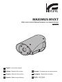
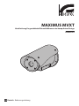
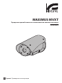
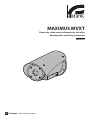
MAXIMUS MVXT
High-spec ex-proof thermal camera in a compact design
Manual B


EN
English - Instruction manual
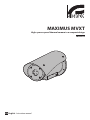
ENGLISH
MAXIMUS MVXT
High-spec ex-proof thermal camera in a compact design
Manual B

EN - English - Instruction manual
2 MNVCMVXTBCAM_2222_EN
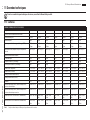
Contents
ENGLISH 1
1 About this manual ....................................................................................................................3
1.1 Typographical conventions ................................................................................................................................................ 3
2 Notes on copyright and information on trademarks ............................................................3
3 Product description and type designation ............................................................................3
3.1 Product marking label .......................................................................................................................................................... 3
3.2 Model identification.............................................................................................................................................................. 4
4 Installation ................................................................................................................................6
4.1 Range of use ............................................................................................................................................................................. 6
4.2 Connecting the power supply .......................................................................................................................................... 6
4.3 Ethernet cable connection ................................................................................................................................................. 7
4.4 I/O cable connection ............................................................................................................................................................ 7
4.4.1 Alarm and relay connections .............................................................................................................................................................. 7
4.4.1.1 Connecting an alarm with dry contact ...................................................................................................................................................................7
4.4.1.2 Relay connection ............................................................................................................................................................................................................8
5 Switching on .............................................................................................................................8
5.1 Before powering the product in an explosive atmosphere ................................................................................... 8
5.2 First start-up ............................................................................................................................................................................. 8
6 Configuration............................................................................................................................9
6.1 Default IP address .................................................................................................................................................................. 9
6.2 Web interface .......................................................................................................................................................................... 9
6.2.1 First access to the web pages ............................................................................................................................................................. 9
7 Accessories ................................................................................................................................9
8 Maintenance ........................................................................................................................... 10
8.1 Firmware updating .............................................................................................................................................................. 10
8.2 Factory Default ..................................................................................................................................................................... 10
9 Troubleshooting .....................................................................................................................10
10 Information on disposal and recycling .............................................................................. 11
11 Technical data ....................................................................................................................... 12
11.1 Cameras .................................................................................................................................................................................. 12

Instruction manual - English - EN
3MNVCMVXTBCAM_2222_EN
1 About this manual
Read all the documentation supplied carefully
before installing and using this product. Keep the
manual in a convenient place for future reference.
1.1 Typographical conventions
DANGER!
High level hazard.
Risk of electric shock. Disconnect the
power supply before proceeding with any
operation, unless indicated otherwise.
DANGER!
Explosion hazard.
Read carefully to avoid danger of
explosion.
CAUTION!
Medium level hazard.
This operation is very important for the
system to function properly. Please read
the procedure described very carefully
and carry it out as instructed.
INFO
Description of system specifications.
We recommend reading this part carefully
in order to understand the subsequent
stages.
2 Notes on copyright and
information on trademarks
The mentioned names of products or companies are
trademarks or registered trademarks.
ONVIF® is a trademark of Onvif, Inc.
3 Product description and
type designation
3.1 Product marking label
See the label attached to the product.

EN - English - Instruction manual
4 MNVCMVXTBCAM_2222_EN
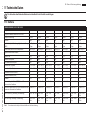
3.2 Model identification
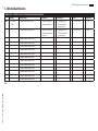
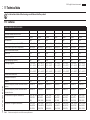
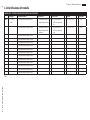
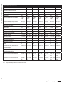
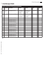
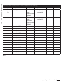
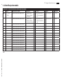
MAXIMUS MVXT CONFIGURATION OPTIONS WITH CABLE GLAND AND ARMOURED CABLE
Voltage Thermal camera Radiometry Connections Model Frequency
MVXT 2 12-24Vdc/
24Vac
Q Thermal camera 9mm, 336x256 0 Thermal camera with
radiometric functions
S A Cable gland Ex d 3/4"
NPT and 4m (13ft)
armoured cable
Z00 T5 -60°C/+65°C B - 7.5Hz
M Thermal camera 13mm, 336x256 R Thermal camera with
advanced radiometric
functions
B Cable gland Ex d 3/4"
NPT and 10m (32.8ft)
armoured cable
02 T6 -60°C/+55°C
H 30Hz
Z Thermal camera 19mm, 336x256
L Thermal camera 25mm, 336x256
I Thermal camera 35mm, 336x256
J Thermal camera 50mm, 336x256
P Thermal camera 60mm, 336x256
H Thermal camera 9mm, 640x512
G Thermal camera 13mm, 640x512
U Thermal camera 19mm, 640x512
E Thermal camera 25mm, 640x512
D Thermal camera 35mm, 640x512
W Thermal camera 50mm, 640x512
K Thermal camera 60mm, 640x512
Tab. 1

Instruction manual - English - EN
5MNVCMVXTBCAM_2222_EN
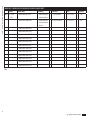
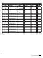
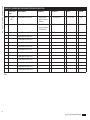
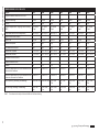
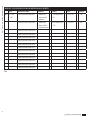
MAXIMUS MVXT CONFIGURATION OPTIONS WITH CABLE TAIL FOR INSTALLATION WITH CONDUIT
Voltage Thermal camera Radiometry Connections Model Frequency
MVXT 2 12-24Vdc/
24Vac
Q Thermal camera 9mm, 336x256 0 Thermal camera with
radiometric functions
S F 4m (13ft) cable tail Z01 T5 -50°C/+65°C B - 7.5Hz
M Thermal camera 13mm, 336x256 R Thermal camera with
advanced radiometric
functions
G 10m (32.8ft) cable tail
03 T6 -50°C/+55°C
H 30Hz
Z Thermal camera 19mm, 336x256
L Thermal camera 25mm, 336x256
I Thermal camera 35mm, 336x256
J Thermal camera 50mm, 336x256
P Thermal camera 60mm, 336x256
H Thermal camera 9mm, 640x512
G Thermal camera 13mm, 640x512
U Thermal camera 19mm, 640x512
E Thermal camera 25mm, 640x512
D Thermal camera 35mm, 640x512
W Thermal camera 50mm, 640x512
K Thermal camera 60mm, 640x512
Tab. 2

EN - English - Instruction manual
6 MNVCMVXTBCAM_2222_EN
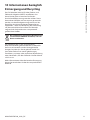
4 Installation
CAUTION! Device installation and
maintaining must be performed by
specialist technical staff only.
The external multipolar cable shield
(armour) must be earthed.
All disconnected wires must be electrically
isolated.
Before installation of the version with
multipolar cable, ensure correct curvature
of the cable is guaranteed (at least
200mm/7.8in).
4.1 Range of use
For indoors and outdoors installation.
Operating temperature:
• Continuous working: from -50°C (-58°F) up to
+65°C (149°F).
• Cold start: up to -40°C (-40°F).
Relative humidity: from 10% up to 95% (no
condensation).
4.2 Connecting the power supply
Electrical connections must be performed
with the power supply disconnected and
the circuit-breaker open.
When commencing installation make
sure that the specifications for the power
supply for the installation correspond with
those required by the device.
Check that the power supply is adequately
dimensioned.
The device can be provided with different power
supply voltages. The power supply voltage is
indicated on the product identification label (3.1
Product marking label, page 3).
Perform the connections following the instructions
reported in the table .
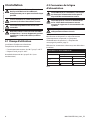
CONNECTING THE POWER SUPPLY
Power supply 24Vac/ 24Vdc/ 12Vdc
Colour/Number Description
24Vac 24Vdc/12Vdc
Black/1 ~V+
Black/2 ~V-
Yellow-Green
Tab. 3

Instruction manual - English - EN
7MNVCMVXTBCAM_2222_EN
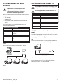
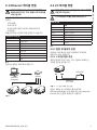
4.3 Ethernet cable connection
The Ethernet cable shield must always be
earthed via the connector. Always use a
shielded RJ45 connector.
Use of Ethernet cables with the following
characteristics is highly recommended:
• STP (shielded)
• Category 5E
• RJ45 connector (crimped in compliance with
standard TIA/EIA-568-B)
The product can be directly connected to an
Ethernet switch.
ETHERNET CABLE CONNECTION
Pin number Core colour
1Orange-White
2Orange
3Green-White
4Blue
5Blue-White
6Green
7Brown-White
8Brown
Tab. 4
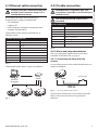
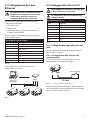
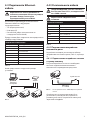
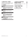
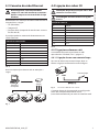
The example below shows a typical installation.
Switch
Personal
Computer
Fig. 1
4.4 I/O cable connection
CAUTION! TNV-1 installation type. The
installation is type TNV-1, do not connect it
to SELV circuits.
The shielding of the I/O cable must be
grounded.
I/O CABLE CONNECTION
Colour Function
White RS-485 A (+)
Yellow RS-485 B (-)
Pink Relay 1, Terminal A
Blue Relay 1, Terminal B
Brown Alarm/Digital input
Green GND/Common alarm
Grey Reset
Tab. 5
4.4.1 Alarm and relay connections
The unit is equipped with the alarms and relays
indicated in the table (Tab. 5, page 7).
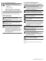
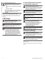
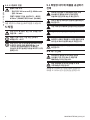
4.4.1.1 Connecting an alarm with dry
contact
In case of free contact alarm make the connection as
shown in the figure.
AL COM
Dry contact
Fig. 2 AL: Alarm. COM: Common alarm.
Clean contact of the alarm can be set NO (normally
open) or NC (normally closed) using the web
interface.

EN - English - Instruction manual
8 MNVCMVXTBCAM_2222_EN
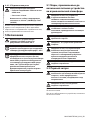
4.4.1.2 Relay connection
Relay operating specifications.
• Working voltage: 30Vac max or 60Vdc
max.
• Current: 1A max.
Use suitable cable sections: from 0.2mm²
(30AWG) up to 1mm² (16AWG).
Due to the absence of polarity, both terminals of the
same relay can be connected either to alternating or
direct current voltages.
5 Switching on
Do not turn on the unit when the ambient
temperature is lower than indicated: -40°C
(-40°F).
The full functionality of the product is
guaranteed from the following ambient
temperature: -40°C (-40°F).
The automatic pre-heating procedure
(De-Ice) activates for 2 hours if on device
switch on an ambient temperature is
detected under -10°C (14°F). The procedure
is necessary to guarantee correct
operation of the devices even at low
temperatures.
5.1 Before powering the product
in an explosive atmosphere
Make sure that the unit and other
components of the installation are closed
so that it is impossible to come into
contact with live parts.
Make sure that the device has been
connected to an earth link as described.
Ensure the rear cover plate is correctly
closed.
Ensure the product is correctly closed.
Ensure that the sealing of cable entry
systems (if any) has been performed
properly and the time of glue hardening
has been observed.
Make sure that all parts are fastened down
firmly and safely.
5.2 First start-up
Ensure the unit and the other components
of the system are appropriately closed to
prevent contact with live parts.
Make sure that all parts are fastened down
firmly and safely.
The unit is switched on by connecting the power
supply.
To switch off the unit disconnect the power.

Instruction manual - English - EN
9MNVCMVXTBCAM_2222_EN
6 Configuration
6.1 Default IP address
The unit is configured to obtain an IP
address from a DHCP server.
The IP address acquired via DHCP is visible in the
DHCP server log file.
If the DHCP server is not available, the unit
automatically configures itself with a self-generated
IP address in the 169.254.x.x/16 subnet. Configuring
the IP address of the PC as belonging to the same
subnet (example: IP address: 169.254.1.1, subnet
mask: 255.255.0.0).
Use an ONVIF compliant VMS or a network sniffer to
find the IP address of the device (IP scan utility).
6.2 Web interface
Browsers supported (the latest version):
Microsoft Edge, Google Chrome, Mozilla
Firefox.
6.2.1 First access to the web pages
The first operation in configuring the device consists
in connecting to the web interface.
To access the web interface of the product, simply
use a browser to connect to http://ip_address.
On first access, the Home page will be displayed.
To configure the web interface, consult the manual
relating to the firmware version installed, available
on the product web page of the website www.
videotec.com.
7 Accessories
For further details on configuration and
use, refer to the manual of the relevant
accessory or support.

EN - English - Instruction manual
10 MNVCMVXTBCAM_2222_EN
8 Maintenance
The pre-installed camera can only be
replaced with one of the same brand and
model.
Read the product Manual A before
performing any operation.
Please provide the device serial number when
requesting any replacement parts.
8.1 Firmware updating
Firmware upgrading can be carried out
directly on the web interface.
If necessary it is possible to update the device
firmware.
For further information please contact the VIDEOTEC
service center.
8.2 Factory Default
It is possible to reset to the factory default settings.
Execute the procedure below:
• Switch off the unit.
• Connect the I/O cable grey and green wires (Tab.
5, page 7).
• Power the unit.
• Wait 30 seconds.
• Disconnect the previously connected grey and
green wires.
• Wait for 2 minutes.
• Switch off the unit.
• Power the unit.
Once the factory default procedure has
finished, you need to configure the unit
as described in chapter: 6.1 Default IP
address, page 9.
9 Troubleshooting
Contact an authorised support centre if
the problems persist or you have any other
issues that are not described here.
Read the product Manual A before
performing any operation.
PROBLEM Video streaming is not
visible.
CAUSE Incorrect IP address settings.
SOLUTION Check the device IP address
and the configuration of the
computer network card.
CAUSE Automatic preheating
procedure (De-Ice) in progress.
SOLUTION Wait until the end of the
pre-heating procedure. If the
ambient temperature is too low
the unit will remain blocked.

Instruction manual - English - EN
11MNVCMVXTBCAM_2222_EN
10 Information on disposal
and recycling
The European Directive 2012/19/EU on Waste
Electrical and Electronic Equipment (WEEE)
mandates that these devices should not be disposed
of in the normal flow of municipal solid waste, but
they should be collected separately in order to
optimize the recovery stream and recycling of the
materials that they contain and to reduce the impact
on human health and the environment due to the
presence of potentially hazardous substances.
The symbol of the crossed out bin is
marked on all products to remember this.
The waste may be delivered to appropriate
collection centers, or may be delivered free of
charge to the distributor where you purchased
the equipment at the time of purchase of a new
equivalent or without obligation to a new purchase
for equipment with size smaller than 25cm (9.8in).
For more information on proper disposal of these
devices, you can contact the responsible public
service.

EN - English - Instruction manual
12 MNVCMVXTBCAM_2222_EN
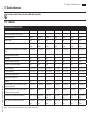
11 Technical data
For the technical data of the housing, consult Manual A of the product.
11.1 Cameras
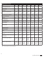
THERMAL CAMERAS RESOLUTION 336X256
Lens 9mm 13mm 19mm 25mm 35mm 50mm 60mm
VOx microbolometer sensor not cooled √√√√√√√
Interpolated resolution 720x480 720x480 720x480 720x480 720x480 720x480 720x480
Pixel dimensions 17μm 17μm 17μm 17μm 17μm 17μm 17μm
Spectral response - long wave infrared (LWIR)
from 7.5μm to 13.5μm from 7.5μm to 13.5μm from 7.5μm to 13.5μm from 7.5μm to 13.5μm from 7.5μm to 13.5μm from 7.5μm to 13.5μm from 7.5μm to 13.5μm
Internal shutter (only for sensor compensation) Video stop <1s Video stop <1s Video stop <1s Video stop <1s Video stop <1s Video stop <1s Video stop <1s
Digital Detail Enhancement (DDE) √√√√√√√
Digital Zoom 2x, 4x 2x, 4x 2x, 4x 2x, 4x 2x, 4x 2x, 4x 2x, 4x
Image updating frequency 7.5f ps 7.5fps 7. 5fps 7. 5fps 7. 5fps 7. 5fps 7.5fps
Image updating high frequency 30fps 30fps 30fps 30fps 30fps 30fps 30fps
Scene range (High Gain) -40°C ÷ +160°C
(-40°F ÷ +320°F)
-40°C ÷ +160°C
(-40°F ÷ +320°F)
-40°C ÷ +160°C
(-40°F ÷ +320°F)
-40°C ÷ +160°C
(-40°F ÷ +320°F)
-40°C ÷ +160°C
(-40°F ÷ +320°F)
-40°C ÷ +160°C
(-40°F ÷ +320°F)
-40°C ÷ +160°C
(-40°F ÷ +320°F)
Scene range (Low Gain) -40°C ÷ +550°C
(-40°F ÷ +1022°F)
-40°C ÷ +550°C
(-40°F ÷ +1022°F)
-40°C ÷ +550°C
(-40°F ÷ +1022°F)
-40°C ÷ +550°C
(-40°F ÷ +1022°F)
-40°C ÷ +550°C
(-40°F ÷ +1022°F)
-40°C ÷ +550°C
(-40°F ÷ +1022°F)
-40°C ÷ +550°C
(-40°F ÷ +1022°F)
Horizontal field of view (HFOV) 35° 25° 17° 13° 9.3° 6.5° 5.5°
Vertical field of view (VFOV) 27° 19° 13° 10° 7.1° 5° 4.2°
f-number f/1.25 f/1.25 f/1.25 f/1.1 f/1.2 f/1.2 f/1.25
Thermal sensitivity (NETD), thermal camera with radiometric
functions
<50mK at f/1.0 <50mK at f/1.0 <50mK at f/1.0 <50mK at f/1.0 <50mK at f/1.0 <50mK at f/1.0 <50mK at f/1.0
Thermal sensitivity (NETD), thermal camera with advanced
radiometric functions
<30mK at f/1.0 <30mK at f/1.0 <30mK at f/1.0 <30mK at f/1.0 <30mK at f/1.0 <30mK at f/1.0 <30mK at f/1.0
Person (detection / recognition / identification) 285m / 71m / 36m
(935ft / 233ft /
118ft)
440m / 112m /
56m (1443ft /
2368ft / 183ft)
640m / 160m /
80m (2099ft /
524ft / 262ft)
930m / 230m /
116m (3051ft /
754ft / 380ft)
1280m / 320m /
160m (4199ft /
1050ft / 525ft)
1700m / 430m /
215m (5577ft /
1410ft / 715ft)
2000m / 510m
/ 255m (6561ft /
1673ft / 836ft)
Car (detection / recognition / identification) 880m / 220m /
108m (2887ft /
722ft / 354ft)
1340m / 340m
/ 170m (4396ft /
1115f t / 557ft)
1950m / 500m
/ 250m (6397ft/
1640ft/ 820ft)
2800m / 710m /
360m (9186ft /
2329ft / 1181ft)
3850m / 950m /
295m (12631ft /
3116ft / 967ft)
5100m / 1320m /
660m (16732ft /
4330ft / 2165ft)
6000m / 1560m /
780m (19685ft /
5118ft / 2559ft)
Tab. 6 Radiometric analysis does not affect camera performance.

Instruction manual - English - EN
13MNVCMVXTBCAM_2222_EN
THERMAL CAMERAS RESOLUTION 640X512
Lens 9mm 13mm 19mm 25mm 35mm 50mm 60mm
VOx microbolometer sensor not cooled √√√√√√√
Interpolated resolution 720x480 720x480 720x480 720x480 720x480 720x480 720x480
Pixel dimensions 17μm 17μm 17μm 17μm 17μm 17μm 17μm
Spectral response - long wave infrared (LWIR) from 7.5μm to
13.5μm
from 7.5μm to
13.5μm
from 7.5μm to
13.5μm
from 7.5μm to
13.5μm
from 7.5μm to
13.5μm
from 7.5μm to
13.5μm
from 7.5μm to
13.5μm
Internal shutter (only for sensor compensation) Video stop <1s Video stop <1s Video stop <1s Video stop <1s Video stop <1s Video stop <1s Video stop <1s
Digital Detail Enhancement (DDE) √√√√√√√
Digital Zoom 2x, 4x, 8x 2x, 4x, 8x 2x, 4x, 8x 2x, 4x, 8x 2x, 4x, 8x 2x, 4x, 8x 2x, 4x, 8x
Image updating frequency 7.5f ps 7.5fps 7. 5fps 7. 5fps 7. 5fps 7. 5fps 7.5fps
Image updating high frequency 30fps 30fps 30fps 30fps 30fps 30fps 30fps
Scene range (High Gain) -40°C ÷ +160°C
(-40°F ÷ +320°F)
-40°C ÷ +160°C
(-40°F ÷ +320°F)
-40°C ÷ +160°C
(-40°F ÷ +320°F)
-40°C ÷ +160°C
(-40°F ÷ +320°F)
-40°C ÷ +160°C
(-40°F ÷ +320°F)
-40°C ÷ +160°C
(-40°F ÷ +320°F)
-40°C ÷ +160°C
(-40°F ÷ +320°F)
Scene range (Low Gain) -40°C ÷ +550°C
(-40°F ÷ +1022°F)
-40°C ÷ +550°C
(-40°F ÷ +1022°F)
-40°C ÷ +550°C
(-40°F ÷ +1022°F)
-40°C ÷ +550°C
(-40°F ÷ +1022°F)
-40°C ÷ +550°C
(-40°F ÷ +1022°F)
-40°C ÷ +550°C
(-40°F ÷ +1022°F)
-40°C ÷ +550°C
(-40°F ÷ +1022°F)
Horizontal field of view (HFOV) 69° 45° 32° 25° 18° 12.4° 10.4°
Vertical field of view (VFOV) 56° 37° 26° 20° 14° 9.9° 8.3°
f-number f/1.4 f/1.25 f/1.25 f/1.1 f/1.2 f/1.2 f/1.25
Thermal sensitivity (NETD), thermal camera with radiome-
tric functions
<50mK at f/1.0 <50mK at f/1.0 <50mK at f/1.0 <50mK at f/1.0 <50mK at f/1.0 <50mK at f/1.0 <50mK at f/1.0
Thermal sensitivity (NETD), thermal camera with advanced
radiometric functions
<30mK at f/1.0 <30mK at f/1.0 <30mK at f/1.0 <30mK at f/1.0 <30mK at f/1.0 <30mK at f/1.0 <30mK at f/1.0
Person (detection / recognition / identification) 250m / 63m / 31m
(820ft / 207ft /
102ft)
390m / 95m / 47m
(1280ft / 312ft /
154ft)
570m / 144m /
72m (1870 / 472 /
236ft)
820m / 210m /
104m (2690ft /
689ft / 341ft)
1140m / 280m /
142m (3740ft /
919ft / 466ft)
1500m / 380m
/ 190m (4921ft /
1247ft / 623ft)
1750m / 450m /
225m (5741ft /
1476ft / 738ft)
Car (detection / recognition / identification) 720m / 175m
/88m (2362 / 574
/ 289ft)
1080m / 275m /
140m (3543ft /
902ft / 459ft)
1550m / 400m /
200m (5085ft /
1312ft / 656ft)
2200m / 580m /
290m (7218ft /
1903ft / 951ft)
3000m / 800m /
200m (9843ft /
2625ft / 656ft)
3900m / 1060m
/ 540m (12795ft /
3478ft / 1772)
4500m / 1240m /
640m (14764ft /
4068ft / 2100ft)
Tab. 7 Radiometric analysis does not affect camera performance.

MNVCMVXTBCAM_2222_EN
Headquarters Italy VIDEOTEC s.r.l.
Via Friuli, 6 - I-36015 Schio (VI) - Italy
Tel. +39 0445 697411 - Fax +39 0445 697414
Email: [email protected]
www.videotec.com

IT
Italiano - Manuale di istruzioni
ITALIANO
MAXIMUS MVXT
Telecamera termica antideflagrante ad alte prestazioni dal design compatto
Manuale B

IT - Italiano - Manuale di istruzioni
2 MNVCMVXTBCAM_2222_IT
Sommario
ITALIANO 1
1 Informazioni sul presente manuale........................................................................................3
1.1 Convenzioni tipografiche .................................................................................................................................................... 3
2 Note sul copyright e informazioni sui marchi commerciali .................................................3
3 Descrizione e designazione del prodotto ..............................................................................3
3.1 Etichetta di marcatura del prodotto ............................................................................................................................... 3
3.2 Identificazione del modello ............................................................................................................................................... 4
4 Installazione .............................................................................................................................6
4.1 Campo di utilizzo .................................................................................................................................................................... 6
4.2 Collegamento della linea di alimentazione ................................................................................................................. 6
4.3 Collegamento del cavo Ethernet ..................................................................................................................................... 7
4.4 Collegamento dei cavi I/O .................................................................................................................................................. 7
4.4.1 Collegamento degli allarmi e dei relè .............................................................................................................................................7
4.4.1.1 Collegamento dell'allarme con contatto pulito..................................................................................................................................................7
4.4.1.2 Collegamento del relè ..................................................................................................................................................................................................8
5 Accensione ................................................................................................................................ 8
5.1 Prima di alimentare il prodotto in atmosfera esplosiva ........................................................................................... 8
5.2 Prima accensione ................................................................................................................................................................... 8
6 Configurazione ......................................................................................................................... 9
6.1 Indirizzo IP di default ............................................................................................................................................................ 9
6.2 Interfaccia web ........................................................................................................................................................................ 9
6.2.1 Primo accesso alle pagine web .......................................................................................................................................................... 9
7 Accessori ...................................................................................................................................9
8 Manutenzione ........................................................................................................................10
8.1 Aggiornamento del firmware .......................................................................................................................................... 10
8.2 Factory Default ..................................................................................................................................................................... 10
9 Risoluzione dei problemi.......................................................................................................10
10 Informazioni sullo smaltimento e il riciclo ........................................................................ 11
11 Dati tecnici ............................................................................................................................ 12
11.1 Telecamere ............................................................................................................................................................................ 12

Manuale di istruzioni - Italiano - IT
3MNVCMVXTBCAM_2222_IT
1 Informazioni sul presente
manuale
Prima di installare e utilizzare questo prodotto
leggere attentamente tutta la documentazione
fornita. Tenere il manuale a portata di mano per
consultazioni successive.
1.1 Convenzioni tipografiche
PERICOLO!
Pericolosità elevata.
Rischio di scosse elettriche. Prima di
eseguire qualsiasi operazione assicurarsi
di togliere tensione al prodotto, salvo
diversa indicazione.
PERICOLO!
Pericolo di esplosione.
Leggere attentamente per evitare pericoli
di esplosione.
ATTENZIONE!
Pericolosità media.
L'operazione è molto importante per
il corretto funzionamento del sistema.
Si prega di leggere attentamente la
procedura indicata e di eseguirla secondo
le modalità previste.
INFO
Descrizione delle caratteristiche del
sistema.
Si consiglia di leggere attentamente per
comprendere le fasi successive.
2 Note sul copyright e
informazioni sui marchi
commerciali
I nomi di prodotto o di aziende citati sono marchi
commerciali o marchi commerciali registrati
appartenenti alle rispettive società.
ONVIF® è un marchio di proprietà di Onvif, Inc.
3 Descrizione e
designazione del prodotto
3.1 Etichetta di marcatura del
prodotto
Vedere l’etichetta posta sul prodotto.

IT - Italiano - Manuale di istruzioni
4 MNVCMVXTBCAM_2222_IT
3.2 Identificazione del modello
MAXIMUS MVXT OPZIONI DI CONFIGURAZIONE CON PRESSACAVO E CAVO ARMATO
Voltaggio Telecamera termica Radiometria Connessioni Modello Frequenza
MVXT 2 12-24Vdc/
24Vac
Q Telecamera termica 9mm, 336x256 0 Telecamera termica con
funzioni radiometriche
S A Pressacavo Ex d 3/4"
NPT e cavo armato da
4m
Z00 T5 -60°C/+65°C B - 7.5Hz
M Telecamera termica 13mm, 336x256 R Telecamera termica con
funzioni radiometriche
avanzate
B Pressacavo Ex d 3/4"
NPT e cavo armato da
10m
02 T6 -60°C/+55°C
H 30Hz
Z Telecamera termica 19mm, 336x256
L Telecamera termica 25mm, 336x256
I Telecamera termica 35mm, 336x256
J Telecamera termica 50mm, 336x256
P Telecamera termica 60mm, 336x256
H Telecamera termica 9mm, 640x512
G Telecamera termica 13mm, 640x512
U Telecamera termica 19mm, 640x512
E Telecamera termica 25mm, 640x512
D Telecamera termica 35mm, 640x512
W Telecamera termica 50mm, 640x512
K Telecamera termica 60mm, 640x512
Tab. 1
A página está carregando...
A página está carregando...
A página está carregando...
A página está carregando...
A página está carregando...
A página está carregando...
A página está carregando...
A página está carregando...
A página está carregando...
A página está carregando...
A página está carregando...
A página está carregando...
A página está carregando...
A página está carregando...
A página está carregando...
A página está carregando...
A página está carregando...
A página está carregando...
A página está carregando...
A página está carregando...
A página está carregando...
A página está carregando...
A página está carregando...
A página está carregando...
A página está carregando...
A página está carregando...
A página está carregando...
A página está carregando...
A página está carregando...
A página está carregando...
A página está carregando...
A página está carregando...
A página está carregando...
A página está carregando...
A página está carregando...
A página está carregando...
A página está carregando...
A página está carregando...
A página está carregando...
A página está carregando...
A página está carregando...
A página está carregando...
A página está carregando...
A página está carregando...
A página está carregando...
A página está carregando...
A página está carregando...
A página está carregando...
A página está carregando...
A página está carregando...
A página está carregando...
A página está carregando...
A página está carregando...
A página está carregando...
A página está carregando...
A página está carregando...
A página está carregando...
A página está carregando...
A página está carregando...
A página está carregando...
A página está carregando...
A página está carregando...
A página está carregando...
A página está carregando...
A página está carregando...
A página está carregando...
A página está carregando...
A página está carregando...
A página está carregando...
A página está carregando...
A página está carregando...
A página está carregando...
A página está carregando...
A página está carregando...
A página está carregando...
A página está carregando...
A página está carregando...
A página está carregando...
A página está carregando...
A página está carregando...
A página está carregando...
A página está carregando...
-
 1
1
-
 2
2
-
 3
3
-
 4
4
-
 5
5
-
 6
6
-
 7
7
-
 8
8
-
 9
9
-
 10
10
-
 11
11
-
 12
12
-
 13
13
-
 14
14
-
 15
15
-
 16
16
-
 17
17
-
 18
18
-
 19
19
-
 20
20
-
 21
21
-
 22
22
-
 23
23
-
 24
24
-
 25
25
-
 26
26
-
 27
27
-
 28
28
-
 29
29
-
 30
30
-
 31
31
-
 32
32
-
 33
33
-
 34
34
-
 35
35
-
 36
36
-
 37
37
-
 38
38
-
 39
39
-
 40
40
-
 41
41
-
 42
42
-
 43
43
-
 44
44
-
 45
45
-
 46
46
-
 47
47
-
 48
48
-
 49
49
-
 50
50
-
 51
51
-
 52
52
-
 53
53
-
 54
54
-
 55
55
-
 56
56
-
 57
57
-
 58
58
-
 59
59
-
 60
60
-
 61
61
-
 62
62
-
 63
63
-
 64
64
-
 65
65
-
 66
66
-
 67
67
-
 68
68
-
 69
69
-
 70
70
-
 71
71
-
 72
72
-
 73
73
-
 74
74
-
 75
75
-
 76
76
-
 77
77
-
 78
78
-
 79
79
-
 80
80
-
 81
81
-
 82
82
-
 83
83
-
 84
84
-
 85
85
-
 86
86
-
 87
87
-
 88
88
-
 89
89
-
 90
90
-
 91
91
-
 92
92
-
 93
93
-
 94
94
-
 95
95
-
 96
96
-
 97
97
-
 98
98
-
 99
99
-
 100
100
-
 101
101
-
 102
102


em outras línguas
- français: Videotec MAXIMUS MVXT Manuel utilisateur
- italiano: Videotec MAXIMUS MVXT Manuale utente
Artigos relacionados
-
Videotec MAXIMUS MVXT Manual do proprietário
-
Videotec MAXIMUS MPXR SERIES2 Manual do usuário
-
-
-
-
-
Videotec Maximus Manual do usuário
-

