
EN
English - Instruction manual
IT
Italiano - Manuale di istruzioni
FR
Français - Manuel d’instructions
DE
Deutsch - Bedienungsanleitung
RU
Русский - Руководство по эксплуатации
PT
Português - Manual de instruções
KO
- 지침 설명서
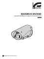
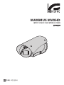
MAXIMUS MVXHD
High-spec ex-proof HD camera in a compact design
Manual B


EN
English - Instruction manual
ENGLISH
MAXIMUS MVXHD
High-spec ex-proof HD camera in a compact design
Manual B

EN - English - Instruction manual
2 MNVCMVXHDBCAM_2121_EN
Contents
ENGLISH 1
1 About this manual ....................................................................................................................3
1.1 Typographical conventions ................................................................................................................................................ 3
2 Notes on copyright and information on trademarks .............................................................3
3 Product description and type designation .............................................................................3
3.1 Product marking label .......................................................................................................................................................... 3
3.2 Model identification .............................................................................................................................................................. 4
4 Installation ................................................................................................................................5
4.1 Range of use ............................................................................................................................................................................. 5
4.2 Connecting the power supply ........................................................................................................................................... 5
4.3 Ethernet cable connection .................................................................................................................................................. 6
4.4 I/O cable connection ............................................................................................................................................................. 6
4.4.1 Alarm and relay connections ...............................................................................................................................................................6
4.4.1.1 Connecting an alarm with dry contact .................................................................................................................................................................... 6
4.4.1.2 Relay connection .............................................................................................................................................................................................................7
4.5 Washing system connection .............................................................................................................................................. 7
5 Switching on .............................................................................................................................7
5.1 Before powering the product in an explosive atmosphere .................................................................................... 7
5.2 First start-up ............................................................................................................................................................................. 7
6 Configuration ............................................................................................................................8
6.1 Default IP address................................................................................................................................................................... 8
6.2 Web interface ........................................................................................................................................................................... 8
6.2.1 First access to the web pages ..............................................................................................................................................................8
7 Accessories ................................................................................................................................ 8
8 Instructions for normal operation ...........................................................................................8
8.1 Enabling the wiper (Wiper) ................................................................................................................................................. 8
8.2 Enabling the washer (Washer) ........................................................................................................................................... 8
9 Maintenance .............................................................................................................................9
9.1 Firmware updating ................................................................................................................................................................ 9
9.2 Factory Default ........................................................................................................................................................................ 9
10 Information on disposal and recycling ............................................................................... 10
11 Troubleshooting ...................................................................................................................10
12 Technical data .......................................................................................................................11
12.1 Cameras ................................................................................................................................................................................. 11

Instruction manual - English - EN
3MNVCMVXHDBCAM_2121_EN
1 About this manual
Read all the documentation supplied carefully before
installing and using this product. Keep the manual in
a convenient place for future reference.
1.1 Typographical conventions
DANGER!
High level hazard.
Risk of electric shock. Disconnect the
power supply before proceeding with any
operation, unless indicated otherwise.
DANGER!
Explosion hazard.
Read carefully to avoid danger of explosion.
CAUTION!
Medium level hazard.
This operation is very important for the
system to function properly. Please read
the procedure described very carefully and
carry it out as instructed.
INFO
Description of system specifications.
We recommend reading this part carefully
in order to understand the subsequent
stages.
2 Notes on copyright and
information on trademarks
The mentioned names of products or companies are
trademarks or registered trademarks.
ONVIF® is a trademark of Onvif, Inc.
3 Product description and
type designation
3.1 Product marking label
See the label attached to the product.

EN - English - Instruction manual
4 MNVCMVXHDBCAM_2121_EN
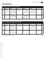
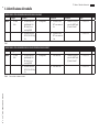
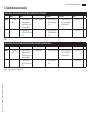
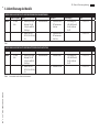
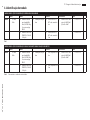
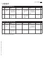
3.2 Model identification
MAXIMUS MVXHD CONFIGURATION OPTIONS WITH CABLE GLAND AND SHIELDED CABLE
Voltage Camera
Connections Video Output Model
MVXHD 2 12-24Vdc/
24Vac
10 Super low-light Day/
Night camera, FULL HD
1080p, 30x, with DELUX
technology
W With wiper A Cable gland Ex d 3/4"
NPT and 4m (13ft)
armoured cable
Z IP H.264/AVC control,
ONVIF protocol Profile
Q, Profile S and Profile T
00 T5 -60°C/+65°C B
20 SONY FCB-EV7520
camera, FULL HD 1080p,
30x
B Cable gland Ex d 3/4"
NPT and 10m (32.8ft)
armoured cable
02 T6 -60°C/+55°C
Tab. 1
MAXIMUS MVXHD CONFIGURATION OPTIONS WITH CABLE TAIL FOR INSTALLATION WITH CONDUIT
Voltage Camera
Connections Video Output Model
MVXHD 2 12-24Vdc/
24Vac
10 Super low-light Day/
Night camera, FULL HD
1080p, 30x, with DELUX
technology
W With wiper F 4m (13ft) cable tail Z IP H.264/AVC control,
ONVIF protocol Profile
Q, Profile S and Profile T
01 T5 -50°C/+65°C B
20 SONY FCB-EV7520
camera, FULL HD 1080p,
30x
G 10m (32.8ft) cable tail
03 T6 -50°C/+55°C
Tab. 2 Conduit sealing fitting and conduit not included.

Instruction manual - English - EN
5MNVCMVXHDBCAM_2121_EN
4 Installation
CAUTION! Device installation and
maintaining must be performed by
specialist technical staff only.
The external multipolar cable shield
(armour) must be earthed.
All disconnected wires must be electrically
isolated.
During installation of the version with
multipolar cable, ensure there is 200mm of
open space at the back of the housing to
guarantee correct curvature of the cable.
4.1 Range of use
For indoors and outdoors installation.
Operating temperature:
• Continuous working: from -50°C (-58°F) up to
+65°C (149°F).
• Cold start: up to -40°C (-40°F).
Relative humidity: from 10% up to 95% (no
condensation).
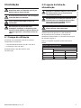
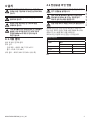
4.2 Connecting the power supply
Electrical connections must be performed
with the power supply disconnected and
the circuit-breaker open.
When commencing installation make sure
that the specifications for the power supply
for the installation correspond with those
required by the device.
Check that the power supply is adequately
dimensioned.
The device can be provided with different power
supply voltages. The power supply voltage is
indicated on the product identification label. (3.1
Product marking label, page 3).
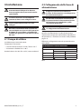
Perform the connections following the instructions
reported in the table .
CONNECTING THE POWER SUPPLY
Power supply 24Vac/ 24Vdc/ 12Vdc
Colour/Number Description
24Vac 24Vdc/12Vdc
Black/1 ~ V+
Black/2 ~ V-
Yellow-Green
Tab. 3

EN - English - Instruction manual
6 MNVCMVXHDBCAM_2121_EN
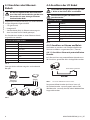
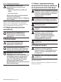
4.3 Ethernet cable connection
The Ethernet cable shield must always be
earthed via the connector. Always use a
shielded RJ45 connector.
Use of Ethernet cables with the following
characteristics is highly recommended:
• STP (shielded)
• Category 5E
• RJ45 connector (crimped in compliance with
standard TIA/EIA-568-B)
The product can be directly connected to an Ethernet
switch.
ETHERNET CABLE CONNECTION
Pin number Core colour
1 Orange-White
2 Orange
3 Green-White
4 Blue
5 Blue-White
6 Green
7 Brown-White
8 Brown
Tab. 4
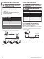
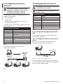
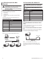
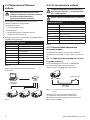
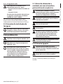
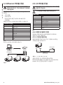
The example below shows a typical installation.
Switch
Personal
Computer
Fig. 1
4.4 I/O cable connection
CAUTION! TNV-1 installation type. The
installation is type TNV-1, do not connect it
to SELV circuits.
The shielding of the I/O cable must be
grounded.
I/O CABLE CONNECTION
Colour Function
White RS-485 A (+)
Yellow RS-485 B (-)
Pink Relay 1, Terminal A
Blue Relay 1, Terminal B
Brown Alarm/Digital input
Green GND/Common alarm
Grey Reset
Tab. 5
4.4.1 Alarm and relay connections
The unit is equipped with the alarms and relays
indicated in the table (Tab. 5, page 6).
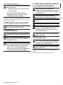
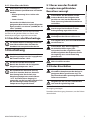
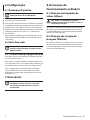
4.4.1.1 Connecting an alarm with dry contact
In case of free contact alarm make the connection as
shown in the figure.
AL COM
Dry contact
Fig. 2 AL: Alarm. COM: Common alarm.
Clean contact of the alarm can be set NO (normally
open) or NC (normally closed) using the web
interface.

Instruction manual - English - EN
7MNVCMVXHDBCAM_2121_EN
4.4.1.2 Relay connection
Each relay is usable with the specifications
described below.
• Working voltage: up to 30Vac or 60Vdc.
• Current: 1A max.
Use suitable cable sections with the
following characteristics: from 0.2mm²
(30AWG) up to 1mm² (16AWG).
Due to the absence of polarity, both terminals of the
same relay can be connected either to alternating or
direct current voltages.
4.5 Washing system connection
For further details on configuration and
use, refer to the relative manual.
5 Switching on
Do not turn on the unit when the ambient
temperature is lower than indicated: -40°C.
The full functionality of the product is
guaranteed from the following ambient
temperature: -40°C.
The automatic pre-heating procedure (De-
Ice) activates for 2 hours if on device switch
on an ambient temperature is detected
under -10 °C (+14°F). The procedure is
necessary to guarantee correct operation of
the devices even at low temperatures.
5.1 Before powering the product
in an explosive atmosphere
Make sure that the unit and other
components of the installation are closed
so that it is impossible to come into contact
with live parts.
Make sure that the device has been
connected to an earth link as described.
Ensure the rear cover plate is correctly
closed.
Ensure the product is correctly closed.
Ensure that the sealing of cable entry
systems (if any) has been performed
properly and the time of glue hardening
has been observed.
Make sure that all parts are fastened down
firmly and safely.
5.2 First start-up
Ensure the unit and the other components
of the system are appropriately closed to
prevent contact with live parts.
Make sure that all parts are fastened down
firmly and safely.
The unit is switched on by connecting the power
supply.
To switch off the unit disconnect the power.

EN - English - Instruction manual
8 MNVCMVXHDBCAM_2121_EN
6 Configuration
6.1 Default IP address
The unit is configured to obtain an IP
address from a DHCP server.
The IP address acquired via DHCP is visible in the
DHCP server log file.
If the DHCP server is not available, the unit
automatically configures itself with a self-generated
IP address in the 169.254.x.x/16 subnet. Configuring
the IP address of the PC as belonging to the same
subnet (example: IP address: 169.254.1.1, subnet
mask: 255.255.0.0).
Use an ONVIF compliant VMS or a network sniffer to
find the IP address of the device (IP scan utility).
6.2 Web interface
Browsers supported (the latest version):
Microsoft Edge, Google Chrome, Mozilla
Firefox.
6.2.1 First access to the web pages
The first operation in configuring the device consists
in connecting to the web interface.
To access the web interface of the product, simply
use a browser to connect to http://ip_address.
On first access, the Home page will be displayed.
To configure the web interface, consult the manual
relating to the firmware version installed, available on
the product web page of the website www.videotec.
com.
7 Accessories
For further details on configuration and
use, refer to the manual of the relevant
accessory or support.
8 Instructions for normal
operation
8.1 Enabling the wiper (Wiper)
Do not use the wiper if the outside
temperature is below 0°C (+32°F) or in case
of ice.
To activate or deactivate this function, refer to the
manual of the control device used or consult the
manual relating to the firmware version installed
(Web Interface manual).
8.2 Enabling the washer (Washer)
To activate or deactivate this function, refer to the
manual of the control device used or consult the
manual relating to the firmware version installed
(Web Interface manual).

Instruction manual - English - EN
9MNVCMVXHDBCAM_2121_EN
9 Maintenance
The pre-installed camera can only be
replaced with one of the same brand and
model.
Read the product Manual A before
performing any operation.
Please provide the device serial number when
requesting any replacement parts.
9.1 Firmware updating
Firmware upgrading can be carried out
directly on the web interface.
If necessary it is possible to update the device
firmware.
For further information please contact the VIDEOTEC
service center.
9.2 Factory Default
It is possible to reset to the factory default settings.
Execute the procedure below:
• Switch off the unit.
• Connect the I/O cable grey and green wires (Tab.
5, page 6).
• Power the unit.
• Wait 30 seconds.
• Disconnect the previously connected green and
grey wires.
• Wait for 2 minutes.
• Switch off the unit.
• Power the unit.
Once the factory default procedure has
finished, you need to configure the unit as
described in chapter (6.1 Default IP address,
page 8).

EN - English - Instruction manual
10 MNVCMVXHDBCAM_2121_EN
10 Information on disposal
and recycling
The European Directive 2012/19/EU on Waste
Electrical and Electronic Equipment (WEEE) mandates
that these devices should not be disposed of in the
normal flow of municipal solid waste, but they should
be collected separately in order to optimize the
recovery stream and recycling of the materials that
they contain and to reduce the impact on human
health and the environment due to the presence of
potentially hazardous substances.
The symbol of the crossed out bin is marked
on all products to remember this.
The waste may be delivered to appropriate collection
centers, or may be delivered free of charge to the
distributor where you purchased the equipment at
the time of purchase of a new equivalent or without
obligation to a new purchase for equipment with size
smaller than 25cm (9.8in).
For more information on proper disposal of these
devices, you can contact the responsible public
service.
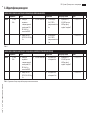
11 Troubleshooting
Contact an authorized support centre if the
problems listed below persist or you have
any other issues that are not described
here.
Read the product Manual A before
performing any operation.
PROBLEM Video streaming is not visible.
CAUSE Incorrect IP address settings.
SOLUTION Check the device IP address
and the configuration of the
computer network card.
CAUSE Automatic preheating
procedure (De-Ice) in progress.
SOLUTION Wait until the end of the pre-
heating procedure. If the ambient
temperature is too low the unit
will remain blocked.
PROBLEM The wash system is blocked
and does not respond to
commands.
CAUSE The wash system is not enabled.
SOLUTION Check the configuration of the
settings.
PROBLEM The wash system settings are
incorrect.
CAUSE Wrong settings in the
configuration.
SOLUTION Check the configuration of the
settings.

Instruction manual - English - EN
11MNVCMVXHDBCAM_2121_EN
12 Technical data
For the technical data of the housing,
consult Manual A of the product.
12.1 Cameras
Day/Night Full HD 30x DELUX
Resolution: Full HD 1080p (1920x1080)
Image Sensor: 1/2.8" Exmor™ R CMOS sensor
Effective Pixels: approx. 2.38 Megapixels
Minimum Illumination:
• Colour: 0.006lx (F1.6, 30 IRE)
• B/W: 0.0006lx (F1.6, 30 IRE)
Focal length: from 4.5mm (wide) up to 135mm (tele)
Zoom: 30x (480x with digital zoom)
Iris: from F1.6 up to F9.6 (Auto, Manual)
Horizontal Viewing Angle: from 61.60° (wide end) up
to 2.50° (tele end)
Vertical Viewing Angle: from 37.07° (wide end) up to
1.44° (tele end)
Shutter speed: from 1/1s up to 1/10000s (Auto,
Manual)
White balance: Auto, Manual
Gain: from 0dB up to 100dB (Auto, Manual)
Wide Dynamic Range: 120dB
Focus System: Auto, Manual, Trigger
Picture Effects: E-flip, Colour enhancement
Noise removal: 2D (3 levels), 3D (3 levels)
Exposure Control: Auto, Manual, Priority (Iris Priority,
Shutter Priority), Brightness, Custom
De-fog: On/Off
Privacy zones masking: maximum 8 settable masks
Indoor Flicker Reduction
Auto Slowshutter: Off, On (from 1/30s up to 1/1s)
Exposure compensation: Off, On (from level 0 up to
level 14)
Sharpness: from level 0 up to level 3
SONY FCB-EV7520 Day/Night Full HD 30x
Resolution: Full HD 1080p (1920x1080)
Image Sensor: 1/2.8" Exmor™ R CMOS sensor
Effective Pixels: approx. 2.13 Megapixels
Minimum Illumination:
• Colour: 0.0013lx (50 IRE, High sensitivity on)
• B/W: 0.0008lx (30 IRE, High sensitivity on)
Focal length: from 4.3mm (wide) up to 129mm (tele)
Zoom: 30x (360x with digital zoom)
Iris: from F1.6 up to F14 (Auto, Manual)
Horizontal Viewing Angle: from 63.7° (wide end) up to
2.3° (tele end)
Vertical Viewing Angle: from 38.5° (wide end) up to
1.3° (tele end)
Shutter speed: from 1/1s up to 1/10000s (Auto,
Manual)
White balance: Auto, Auto Tracing, Indoor,
Outdoor, Manual, Outdoor Auto, Sodium Lamp
(Fix/Auto/Outdoor Auto)
Gain: from 0dB up to 50.0dB (Auto, Manual)
Wide Dynamic Range: 120dB
Focus System: Auto (PTZ Trigger, Full Auto), Manual
Picture Effects: E-flip
Noise removal (2D, 3D): Off, On (from level 1 up to
level 5)
Exposure Control: Auto, Manual, Priority (Shutter
priority, Iris priority, Brightness priority)
De-fog: Off, Low, Mid, High
Dynamic masking of privacy zones: maximum
24 masks settable, maximum 8 simultaneously
displayable
Indoor Flicker Reduction
Gain Limit: from10.7dB up to 50dB
High sensitivity: On/Off
Backlight Compensation: On/Off
Auto Slowshutter: On/Off
Exposure compensation: Off, On (from -10.5dB up to
+10.5dB)
Sharpness: from level 0 up to level 15
High Light Compensation (HLC): Off, Low, Mid, High,
Masking Level (Off, On, from level 1 up to level 15)
Digital image stabilization: On/Off

MNVCMVXHDBCAM_2121_EN
Headquarters Italy VIDEOTEC S.p.A.
Via Friuli, 6 - I-36015 Schio (VI) - Italy
Tel. +39 0445 697411 - Fax +39 0445 697414
Email: [email protected]
www.videotec.com

IT
Italiano - Manuale di istruzioni
ITALIANO
MAXIMUS MVXHD
Telecamera HD antideflagrante ad alte prestazioni dal design compatto
Manuale B

IT - Italiano - Manuale di istruzioni
2 MNVCMVXHDBCAM_2121_IT
Sommario
ITALIANO 1
1 Informazioni sul presente manuale ........................................................................................3
1.1 Convenzioni tipografiche .................................................................................................................................................... 3
2 Note sul copyright e informazioni sui marchi commerciali ...................................................3
3 Descrizione e designazione del prodotto ...............................................................................3
3.1 Etichetta di marcatura del prodotto ................................................................................................................................ 3
3.2 Identificazione del modello ................................................................................................................................................ 4
4 Installazione ..............................................................................................................................5
4.1 Campo di utilizzo .................................................................................................................................................................... 5
4.2 Collegamento della linea di alimentazione .................................................................................................................. 5
4.3 Collegamento del cavo Ethernet ...................................................................................................................................... 6
4.4 Collegamento dei cavi I/O ................................................................................................................................................... 6
4.4.1 Collegamento degli allarmi e dei relè ..............................................................................................................................................6
4.4.1.1 Collegamento allarme con contatto pulito ............................................................................................................................................................6
4.4.1.2 Collegamento del relè ...................................................................................................................................................................................................7
4.5 Collegamento dell'impianto di lavaggio ....................................................................................................................... 7
5 Accensione ................................................................................................................................ 7
5.1 Prima di alimentare il prodotto in atmosfera esplosiva............................................................................................ 7
5.2 Prima accensione .................................................................................................................................................................... 7
6 Configurazione .........................................................................................................................8
6.1 Indirizzo IP di default............................................................................................................................................................. 8
6.2 Interfaccia web ........................................................................................................................................................................ 8
6.2.1 Primo accesso alle pagine web ........................................................................................................................................................... 8
7 Accessori .................................................................................................................................... 8
8 Istruzioni di funzionamento ordinario ...................................................................................8
8.1 Attivazione del tergicristallo (Wiper) ............................................................................................................................... 8
8.2 Attivazione dell'impianto di lavaggio (Washer) .......................................................................................................... 8
9 Manutenzione ...........................................................................................................................9
9.1 Aggiornamento del firmware ............................................................................................................................................ 9
9.2 Factory Default ........................................................................................................................................................................ 9
10 Informazioni sullo smaltimento e il riciclo .........................................................................10
11 Risoluzione dei problemi ..................................................................................................... 10
12 Dati tecnici ............................................................................................................................11
12.1 Telecamere ...........................................................................................................................................................................11

Manuale di istruzioni - Italiano - IT
3MNVCMVXHDBCAM_2121_IT
1 Informazioni sul presente
manuale
Prima di installare e utilizzare questo prodotto
leggere attentamente tutta la documentazione
fornita. Tenere il manuale a portata di mano per
consultazioni successive.
1.1 Convenzioni tipografiche
PERICOLO!
Pericolosità elevata.
Rischio di scosse elettriche. Prima di
eseguire qualsiasi operazione assicurarsi di
togliere tensione al prodotto, salvo diversa
indicazione.
PERICOLO!
Pericolo di esplosione.
Leggere attentamente per evitare pericoli
di esplosione.
ATTENZIONE!
Pericolosità media.
L'operazione è molto importante per il
corretto funzionamento del sistema. Si
prega di leggere attentamente la procedura
indicata e di eseguirla secondo le modalità
previste.
INFO
Descrizione delle caratteristiche del
sistema.
Si consiglia di leggere attentamente per
comprendere le fasi successive.
2 Note sul copyright e
informazioni sui marchi
commerciali
I nomi di prodotto o di aziende citati sono marchi
commerciali o marchi commerciali registrati
appartenenti alle rispettive società.
ONVIF® è un marchio di proprietà di Onvif, Inc.
3 Descrizione e
designazione del prodotto
3.1 Etichetta di marcatura del
prodotto
Vedere l’etichetta posta sul prodotto.

IT - Italiano - Manuale di istruzioni
4 MNVCMVXHDBCAM_2121_IT
3.2 Identificazione del modello
MAXIMUS MVXHD OPZIONI DI CONFIGURAZIONE CON PRESSACAVO E CAVO ARMATO
Voltaggio Telecamera
Connessioni Uscita Video Modello
MVXHD 2 12-24Vdc/
24Vac
10 Telecamera super low-
light Day/Night, FULL
HD 1080p, 30x, con
tecnologia DELUX
W Con tergicristallo A Pressacavo Ex d 3/4"
NPT e cavo armato da
4m
Z Controllo IP H.264/AVC,
protocollo ONVIF Profilo
Q, Profilo S e Profilo T
00 T5 -60°C/+65°C B
20 Telecamera SONY FCB-
EV7520, FULL HD 1080p,
30x
B Pressacavo Ex d 3/4"
NPT e cavo armato da
10m
02 T6 -60°C/+55°C
Tab. 1
MAXIMUS MVXHD OPZIONI DI CONFIGURAZIONE CON CODA CAVI PER INSTALLAZIONE CON CONDUIT
Voltaggio Telecamera
Connessioni Uscita Video Modello
MVXHD 2 12-24Vdc/
24Vac
10 Telecamera super low-
light Day/Night, FULL
HD 1080p, 30x, con
tecnologia DELUX
W Con tergicristallo F Coda cavi da 4m Z Controllo IP H.264/AVC,
protocollo ONVIF Profilo
Q, Profilo S e Profilo T
01 T5 -50°C/+65°C B
20 Telecamera SONY FCB-
EV7520, FULL HD 1080p,
30x
G Coda cavi da 10m
03 T6 -50°C/+55°C
Tab. 2 Porta conduit e conduit non inclusi.

Manuale di istruzioni - Italiano - IT
5MNVCMVXHDBCAM_2121_IT
4 Installazione
ATTENZIONE! L'installazione e la
manutenzione del dispositivo devono
essere eseguite solo da personale tecnico
specializzato.
La calza esterna del cavo multipolare
(armatura) deve essere collegata a terra.
Isolare elettricamente tutti i cavi non
collegati.
Durante l'installazione della versione con
cavo multipolare assicurarsi della presenza
di 200mm di spazio libero sul fondo della
custodia per garantire la corretta curvatura
del cavo.
4.1 Campo di utilizzo
Installazione per interni ed esterni.
Temperatura di esercizio:
• Funzionamento continuo: da -50°C fino a +65°C.
• Avviamento a freddo: fino a -40°C.
Umidità relativa: da 10% fino a 95% (senza condensa).
4.2 Collegamento della linea di
alimentazione
Eseguire le connessioni elettriche in
assenza di alimentazione e con dispositivo
di sezionamento aperto.
All’atto dell’installazione controllare che
le caratteristiche di alimentazione fornite
dall’impianto corrispondano a quelle
richieste dal dispositivo.
Verificare che la sorgente di alimentazione
sia adeguatamente dimensionata.
Al dispositivo possono essere fornite diverse
tensioni di alimentazione. Il valore di tensione di
alimentazione è riportato nell'etichetta identificativa
del prodotto (3.1 Etichetta di marcatura del prodotto,
pagina 3).
Effettuare i collegamenti secondo quanto descritto
nella tabella.
COLLEGAMENTO DELLA LINEA DI ALIMENTAZIONE
Alimentazione 24Vac/ 24Vdc/ 12Vdc
Colore/Numero Descrizione
24Vac 24Vdc/12Vdc
Nero/1 ~ V+
Nero/2 ~ V-
Giallo-Verde
Tab. 3

IT - Italiano - Manuale di istruzioni
6 MNVCMVXHDBCAM_2121_IT
4.3 Collegamento del cavo
Ethernet
La schermatura del cavo Ethernet deve
sempre essere collegata a terra tramite
il connettore. Utilizzare sempre un
connettore RJ45 di tipo schermato.
Si raccomanda l'utilizzo di cavi Ethernet con le
seguenti caratteristiche:
• STP (schermato)
• Categoria 5E
• Connettore RJ45 (crimpato in accordo con lo
standard TIA/EIA-568-B)
Il prodotto può essere collegato direttamente ad uno
switch Ethernet.
COLLEGAMENTO DEL CAVO ETHERNET
Numero del pin Colore dell'anima
1 Arancione-Bianco
2 Arancione
3 Verde-Bianco
4 Blu
5 Blu-Bianco
6 Verde
7 Marrone-Bianco
8 Marrone
Tab. 4
Una installazione tipica è quella riportata
nell’esempio sottostante.
Switch
Personal
Computer
Fig. 1
4.4 Collegamento dei cavi I/O
ATTENZIONE! L'installazione è di tipo TNV-1.
Non collegare a circuiti SELV.
La schermatura del cavo I/O deve essere
collegata a terra.
COLLEGAMENTO DEI CAVI I/O
Colore Funzione
Bianco RS-485 A (+)
Giallo RS-485 B (-)
Rosa Relè 1, Terminale A
Blu Relè 1, Terminale B
Marrone Allarme/Ingresso digitale
Verde GND/Comune allarme
Grigio Reset
Tab. 5
4.4.1 Collegamento degli allarmi e dei
relè
L’unità è dotata degli allarmi e dei relè riportati in
tabella (Tab. 5, pagina 6).
4.4.1.1 Collegamento allarme con contatto
pulito
Nel caso di allarme a contatto pulito eseguire il
collegamento come illustrato in figura.
AL COM
Contatto pulito
Fig. 2 AL: Allarme. COM: Comune allarme.
Il contatto pulito di allarme può essere configurato
NO (normalmente aperto) oppure NC (normalmente
chiuso) tramite l'interfaccia web.
A página está carregando...
A página está carregando...
A página está carregando...
A página está carregando...
A página está carregando...
A página está carregando...
A página está carregando...
A página está carregando...
A página está carregando...
A página está carregando...
A página está carregando...
A página está carregando...
A página está carregando...
A página está carregando...
A página está carregando...
A página está carregando...
A página está carregando...
A página está carregando...
A página está carregando...
A página está carregando...
A página está carregando...
A página está carregando...
A página está carregando...
A página está carregando...
A página está carregando...
A página está carregando...
A página está carregando...
A página está carregando...
A página está carregando...
A página está carregando...
A página está carregando...
A página está carregando...
A página está carregando...
A página está carregando...
A página está carregando...
A página está carregando...
A página está carregando...
A página está carregando...
A página está carregando...
A página está carregando...
A página está carregando...
A página está carregando...
A página está carregando...
A página está carregando...
A página está carregando...
A página está carregando...
A página está carregando...
A página está carregando...
A página está carregando...
A página está carregando...
A página está carregando...
A página está carregando...
A página está carregando...
A página está carregando...
A página está carregando...
A página está carregando...
A página está carregando...
A página está carregando...
A página está carregando...
A página está carregando...
A página está carregando...
A página está carregando...
A página está carregando...
A página está carregando...
A página está carregando...
A página está carregando...
A página está carregando...
A página está carregando...
-
 1
1
-
 2
2
-
 3
3
-
 4
4
-
 5
5
-
 6
6
-
 7
7
-
 8
8
-
 9
9
-
 10
10
-
 11
11
-
 12
12
-
 13
13
-
 14
14
-
 15
15
-
 16
16
-
 17
17
-
 18
18
-
 19
19
-
 20
20
-
 21
21
-
 22
22
-
 23
23
-
 24
24
-
 25
25
-
 26
26
-
 27
27
-
 28
28
-
 29
29
-
 30
30
-
 31
31
-
 32
32
-
 33
33
-
 34
34
-
 35
35
-
 36
36
-
 37
37
-
 38
38
-
 39
39
-
 40
40
-
 41
41
-
 42
42
-
 43
43
-
 44
44
-
 45
45
-
 46
46
-
 47
47
-
 48
48
-
 49
49
-
 50
50
-
 51
51
-
 52
52
-
 53
53
-
 54
54
-
 55
55
-
 56
56
-
 57
57
-
 58
58
-
 59
59
-
 60
60
-
 61
61
-
 62
62
-
 63
63
-
 64
64
-
 65
65
-
 66
66
-
 67
67
-
 68
68
-
 69
69
-
 70
70
-
 71
71
-
 72
72
-
 73
73
-
 74
74
-
 75
75
-
 76
76
-
 77
77
-
 78
78
-
 79
79
-
 80
80
-
 81
81
-
 82
82
-
 83
83
-
 84
84
-
 85
85
-
 86
86
-
 87
87
-
 88
88


em outras línguas
- français: Videotec Maximus Manuel utilisateur
- italiano: Videotec Maximus Manuale utente
Artigos relacionados
-
Videotec MAXIMUS MVXHD Manual do usuário
-
Videotec MAXIMUS MVX DELUX Manual do usuário
-
-
-
Videotec MAXIMUS MPXR SERIES2 Manual do usuário
-
-
-
-
-