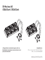
ekwb EK-Nucleus AIO CR360 Dark Guia de instalação
- Tipo
- Guia de instalação

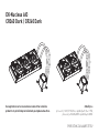
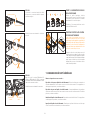
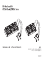
INSTALLATION MANUAL
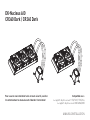
EKNucleus AIO
CR360 Dark / CR240 Dark
Compatible with:
Intel Socket 115X/1200/1700/20xx CPUs
AMD Socket AM4/AM5 CPUs
To ensure safe and easy installation, please carefully read
this manual before beginning the installation process!
1st Revision

1. SAFETY PRECAUTIONS 4
2. SPECIFICATIONS 4
3. ENCLOSED IN THIS PACKAGE 5
ACCESSORY BOX 5
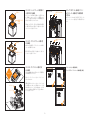
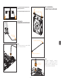
4. INSTALLATION INTEL LGA 115X/1200/1700 SOCKET 6
STEP 1: REMOVING THE MOTHERBOARD 6
STEP 2: ATTACHING THE BACKPLATE TO THE MOTHERBOARD 6
STEP 3: ATTACHING MOUNTING SCREWS 6
STEP 4: INSTALLING THE FANS TO THE RADIATOR 6
STEP 5: REMOVING THE COLD-PLATE PROTECTIVE COVER 6
STEP 6: MOUNTING-BRACKETS INSTALLATION 6
STEP 7: PUMP UNIT INSTALL ATION 6
STEP 8: INSTALLING THE ASSEMBLY OF FANS AND RADIATOR INTO A PC CASE 7
STEP 9: PUMP – CONNECTING CABLES 7
STEP 10: FANS – CONNECTING CABLES 8
STEP 11: PUMP TOP ORIENTATION 9
OPTIONAL STEP! APPLYING THE THERMAL COMPOUND 9
5. INSTALLATION INTEL LGA 20XX SOCKET 9
STEP 1: ATTACHING MOUNTING SCREWS (LGA 20XX) 9
6. INSTALLATION AMD AM4/AM5 SOCKET 9
STEP 1: REMOVING OF THE ORIGINAL PLASTIC HOLD-DOWN CLAMPS (AMD) 9
STEP 2: ATTACHING MOUNTING SCREWS (AMD) 9
STEP 3: INSTALLING THE FANS TO THE RADIATOR (AMD) 9
STEP 4: REMOVING THE COLD-PLATE PROTECTIVE COVER (AMD) 10
STEP 5: MOUNTING-BRACKETS INSTALLATION (AMD) 10
STEP 6: PUMP UNIT INSTALLATION (AMD) 10
STEP 7: INSTALLING THE ASSEMBLY OF FANS AND RADIATOR INTO A PC CASE (AMD) 10
STEP 8: PUMP – CONNECTING CABLES (AMD) 11
STEP 9: FANS – CONNECTING CABLES (AMD) 11
STEP 10: PUMP TOP ORIENTATION (AMD) 12
OPTIONAL STEP! APPLYING THE THERMAL COMPOUND 12
7. GENERAL SAFETY WARNINGS 12
8. SUPPORT AND SERVICE 13
9. SOCIAL MEDIA 13
TABLE OF CONTENTS

- 4 -
Please follow the instructions in this manual for proper installation. Improper installation
may result in damage to your equipment. EK Water Blocks assumes no liability whatsoever,
expressed or implied, for the use of these products, nor their installation. The following
instructions are subject to change without notice. Please visit our website at www.ekwb.com
for updates.
1. SAFETY PRECAUTIONS
1. Keep and store the product away from the reach of children.
2. Check the component list and condition of the product before installation. If there is any
problem, contact the shop where you purchased the product to get a replacement or refund.
3. EKWB d.o.o. is not responsible for any damages due to external causes, including but not
limited to, improper use, problems with electrical power, accident, neglect, alteration, repair,
improper installation, and improper testing.
4. CPU and motherboard are subject to damage if the product is incorrectly installed.
5. Excessive force exerted on the fan may cause damage to the fan and/or system.
6. This product is a CPU liquid cooling solution kit, composed of individual, original EKWB parts.
Combining this liquid cooling unit with parts, other than EK Water Blocks products, may lead
to warranty loss.
7. Product design and specifi cations may be revised to improve quality and performance.
8. You must not run the pump below 20% RPM. The pump must stay within a 20-100% PWM
duty cycle at all times. We recommend always running the pump at 100%. (For help on how to
control the PWM, please refer to your motherboard instructions.)
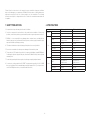
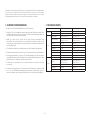
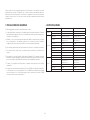
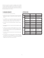
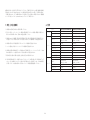
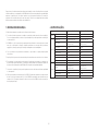
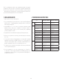
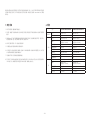
2. SPECIFICATIONS
Model EK-Nucleus AIO CR240 Dark EK-Nucleus AIO CR360 Dark
Radiator Dimensions 277x120x27 mm 398x120x27 mm
Fin material Al Al
Fan
Dimensions 120x120x25 mm (2x) 120x120x25 mm (3x)
Speed 550-2300 RPM ±10%
(PWM: 20-100%)
550-2300 RPM ±10%
(PWM: 20-100%)
Air Flow 72 CFM 72 CFM
Life Expectancy 70.000 hours 70.000 hours
Noise Level 36 dB 36 dB
Bearing Type FDB bearing FDB bearing
Fan Connector 4Pin 4Pin
Fan Rated Voltage 12V 12V
Pump
Dimensions (mm) 82.3x69.2x61.6 mm 82.3x69.2x61.6 mm
RPM 3100 RPM ± 10%
(PWM: 20-100%)
3100 RPM ± 10%
(PWM: 20-100%)
Life Expectancy 70.000 hours 70.000 hours
Noise Level 18.5 dB 18.5 dB
Input Current 0.37 ±10% A 0.37 ±10% A

- 5 -
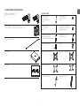
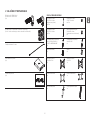
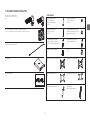
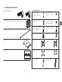
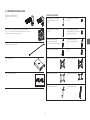
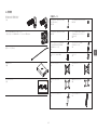
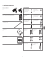
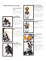
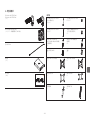
3. ENCLOSED IN THIS PACKAGE
E K- F P T FA N 12 0 E R F ul l Pr e s su re Te c h n o lo g y
(2x / 3x – number of fans depends on the AIO version)
EK-Nucleus AIO CR240 Dark /
EK-Nucleus AIO CR360 Dark
(1x)
Tube of Thermal Paste
1x
ACCESSORY BOX
Phillips Head Screw
UNC 6-32 x 30mm
(4 mm thread length)
8x / 12x
Phillips Head Screw
UNC 6-32 x 34mm
8x / 12x
Phillips Head Screw
UNC 6-32 x 6mm
8x / 12x
Mounting Plate Phillips Head
M3x4mm (for the installation of
mounting brackets)
4x
Mounting thumb screw for
Intel LGA 115x/LGA1200/
LGA1700/AMD AM4/AM5 socket
4x
Mounting thumb screw for
Intel LGA 20XX socket
4x
Thumb nut (Intel /AMD)
4x
Spring
4x
Intel LGA 115x/1200 Backplate
1x
Intel mounting bracket
1x
Intel LGA 1700 Backplate
1x
AMD mounting bracket
1x
Mounting Screw Tool
1x
Extension cable 500mm
Accessory box
(1x)
User Manual
(1x)
INSTALLATION MANUAL
EKNucleus AIO
CR360 Dark / CR240 Dark
Compatible with:
Intel Socket 115X/1200/1700/20xx CPUs
AMD Socket AM4/AM5 CPUs
To ensure safe and easy installation, please carefully read
this manual before beginning the installation process!
1st Revision

- 6 -
Thumb Nut
Spring
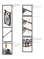
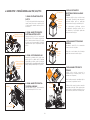
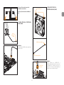
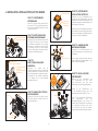
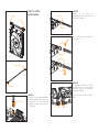
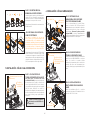
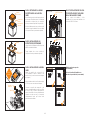
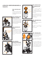
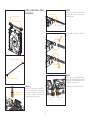
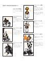
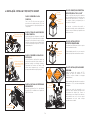
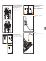
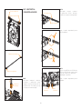
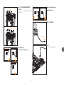
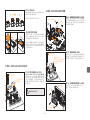
4. INSTALLATION INTEL LGA 115X/1200/1700 SOCKET
STEP 1: REMOVING THE
MOTHERBOARD
If your PC case doesn’t have a cutout from the
bottom CPU side of the motherboard, you will
fi rst need to remove the motherboard from
your computer.
STEP 2: ATTACHING THE BACKPLATE
TO THE MOTHERBOARD
Install the Intel backplate for LGA
115x/1200/1700 socket to the back of your
motherboard. Choose the right backplate
depending on which chipset you are using.
Align the holes on the motherboard with the
holes on the backplate.
Intel LGA 115x / 1200
or 1700 Backplate
STEP 3: ATTACHING MOUNTING
SCREWS
Install 4x mounting thumb screws through
your motherboard to the backplate. The
screws can be installed by using Mounting
Screw Tool. Do not use other tools, because
you may damage the motherboard. (i.e. pliers).
Mounting thumb
screw for INTEL
LGA 115x / 1200
/ 1700 and AMD
AM4/AM5 socket
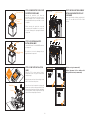
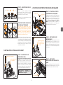
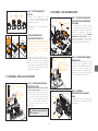
STEP 6: MOUNTING-BRACKETS
INSTALLATION
Use 4x M3x4 screws to install Intel bracket on
the pump unit.
Be careful not to touch or damage the pre-
applied thermal compound.
M3x4
Intel Mounting
Bracket
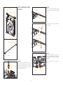
STEP 4: INSTALLING THE FANS TO
THE RADIATOR
Assemble the fans (2x or 3x ... depending on
the AIO version) to the radiator with the UNC
6-32 x 30mm screws.
UNC
6-32 x 30 mm
Fan
Radiator
Mounting Screw Tool
STEP 5: REMOVING THE COLD-PLATE
PROTECTIVE COVER
Remove the protective cover from the
backside of the pump unit. It is there only to
prevent damage to the cold-plate and the
pre-applied thermal compound that is on the
cold-plate.
When removing the protective cover and
proceeding with installation, be careful not
to touch or damage the pre-applied thermal
compound.
STEP 7: PUMP UNIT INSTALLATION
Wipe the CPU’s contact surface (using a
non-abrasive cloth or a Q-tip as shown in the
sample image).
Align the pump unit over the mounting screws
and CPU as shown in the picture.
Place the enclosed compression springs and
thumb nuts over the mounting screws (4x).
Start fastening two thumb nuts at a time,
preferably in a cross pattern, and do not
tighten them fully until all of them are partially
screwed in.
Non-abrasive
cloth IHS
Protective Cover
Pre-applied
thermal
Compound

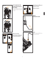
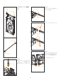
- 7 -
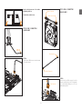
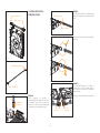
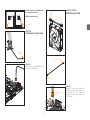
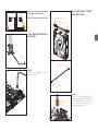
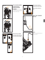
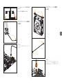
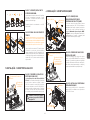
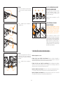
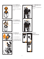
STEP 9: PUMP – CONNECTING
CABLES
4-pin
PWM
STEP A:
Plug the 4-pin PWM connector from the pump
to the motherboard.
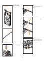
STEP 8: INSTALLING THE ASSEMBLY
OF FANS AND RADIATOR INTO A PC
CASE
Attach the assembly of radiator and the fan(s)
to the PC case with the UNC 6-32 x 6mm
screws.
EK-AIO Nucleus 240
EK-AIO Nucleus 360
UNC 6-32 x 6 mm
(8x)
UNC 6-32 x 6 mm
(12x)
Radiator on top (recommended)
Vertical placement of the radiator with
tubing at the bottom (recommended)
Avoid vertical placement of the radiator
with tubing at the top
Avoid radiator at the bottom

- 8 -
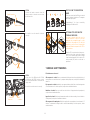
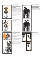
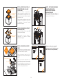
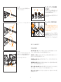
STEP A:
Connect the 4-pin fan connector from the
extension cable directly to the CPU fan header
on the motherboard. Always use CPU fan
header when possible.
STEP 10: FANS – CONNECTING
CABLES
Fan Connector
Male Connector
Female Connector
Fan Connector
Female Connector
STEP B:
Connect the female connector from the
extension cable to the male connector from
the fi rst fan in line.
Be careful to turn the micro-fi t connector
correctly.
Male Connector
Female Connector
STEP C:
In the case of the EK-Nucleus AIO CR240
or EK-Nucleus AIO CR360 version, connect
the second and third fan in series with the
“daisy-chain”.
Be careful to turn the connector correctly.
Male
Connector
Female
Connector

- 9 -
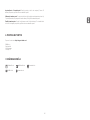
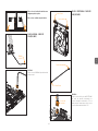
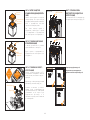
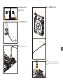
5. INSTALLATION INTEL LGA 20XX SOCKET
STEP 1: ATTACHING MOUNTING
SCREWS (LGA 20XX)
LGA 20xx (2066 / 2011 V3 / 2011) socket
motherboards do not require backplate
installation. Install 4x LGA 20XX mounting
thumb screws into M4 threaded stubs on the
LGA 20XX socket integrated latch
mechanism (ILM). The screws can be
installed by using Mounting Screw Tool.
Do not use other tools, because you may
damage the motherboard. (i.e. pliers).
Continue installation by following
the instructions from Step 4 on
page 6
OPTIONAL STEP! APPLYING THE
THERMAL COMPOUND
This step is relevant only in the case of a
second installation of AIO or if you have
damaged the pre-applied paste on the
backside of the pump unit. For the fi rst
installation, you don’t need to apply the
additional thermal compound to the CPU’s
contact surface.
Wipe the CPU’s contact surface (using a non–
abrasive cloth or Q-tip, as shown in sample
photo). On a clean IHS, apply a line of thermal
compound and spread it over the whole
CPU heat spreader (IHS) with a credit card or
equivalent.
12 34
LGA 20XX M3.5
Thumb Screw
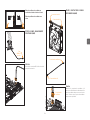
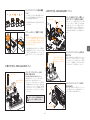
6. INSTALLATION AMD AM4/AM5 SOCKET
STEP 1: REMOVING OF THE
ORIGINAL PLASTIC HOLD-DOWN
CLAMPS (AMD)
Using a Philips head screwdriver, remove the
four UNC 6-32 screws securing the original
plastic hold-down clamps around the socket
as shown on the sketch. Keep the original
AMD® backplate and remove the hold-down
clamps and store them away. See the image for
further part identifi cation.
STEP 2: ATTACHING MOUNTING
SCREWS (AMD)
Install 4x mounting thumb screw for AMD
AM4/AM5 socket onto your motherboard. The
screws can be installed by using Mounting
Screw Tool. Do not use other tools, because
you may damage the motherboard. (i.e. pliers).
Mounting thumb
screw for INTEL
LGA 115x / 1200
/ 1700 and AMD
AM4/AM5 socket
Hold-down
clamps
UNC 6-32 Screws
STEP 3: INSTALLING THE FANS TO
THE RADIATOR (AMD)
Assemble the fans (2x or 3x ... depending on
the AIO version) to the radiator with the UNC
6-32 x 30mm screws.
STEP 11: PUMP TOP ORIENTATION
Lift the top, rotate it until the EK logo is oriented
correctly, and put it back down. The magnets
will hold the top in place.
Congratulations! You have successfully
installed your EK-Nucleus AIO.
Non-abrasive
Cloth
IHS
UNC
6-32 x 30 mm
Fan
Radiator
Mounting Screw Tool
Mounting Screw Tool

- 10 -
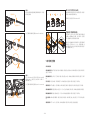
STEP 7: INSTALLING THE ASSEMBLY
OF FANS AND RADIATOR INTO A PC
CASE (AMD)
Attach the assembly of radiator and the fan(s)
to the PC case with the UNC 6-32 x 6mm
screws.
Radiator on top (recommended)
Vertical placement of the radiator with
tubing at the bottom (recommended)
STEP 5: MOUNTING-BRACKETS
INSTALLATION (AMD)
Use 4x M3x4 screws to install AMD bracket on
the pump unit.
Be careful not to touch or damage the pre-
applied thermal compound.
STEP 4: REMOVING THE COLD-PLATE
PROTECTIVE COVER (AMD)
Remove the protective cover from the
backside of the pump unit. It is there only to
prevent damage to the cold-plate and the
pre-applied thermal compound that is on the
cold-plate.
When removing the protective cover and
proceeding with installation be careful not
to touch or damage the pre-applied thermal
compound.
STEP 6: PUMP UNIT INSTALLATION
(AMD)
Wipe the CPU’s contact surface (using a
non-abrasive cloth or a Q-tip as shown in the
sample image).
Align the pump unit over the mounting screws
and CPU as shown in the picture.
Place the enclosed compression springs and
thumb nuts over the mounting screws (4x). Start
fastening two thumb nuts at a time, preferably
in a cross pattern, and do not tighten them fully
until all of them are partially screwed in.
Thumb Nut
Spring
Non-abrasive
cloth IHS
Protective Cover
Pre-applied
thermal
Compound
M3x4
AMD Mounting
Bracket
EK-AIO Nucleus 240
EK-AIO Nucleus 360
UNC 6-32 x 6 mm
(8x)
UNC 6-32 x 6 mm
(12x)

- 11 -
Avoid vertical placement of the radiator
with tubing at the top
Avoid radiator at the bottom
STEP A:
Connect the 4-pin FAN connector from the
extension cable directly to the CPU fan header
on the motherboard. Always use a CPU fan
header when possible.
STEP 9: FANS – CONNECTING
CABLES (AMD)
Fan Connector
Male Connector
Female Connector
STEP 8: PUMP – CONNECTING
CABLES (AMD)
4-pin
PWM
STEP A:
Plug the 4-pin PWM connector from the pump
to the motherboard.
Fan Connector
Female Connector

- 12 -
OPTIONAL STEP! APPLYING THE
THERMAL COMPOUND
This step is relevant only in the case of a
second installation of AIO or if you have
damaged the pre-applied paste on the
backside of the pump unit. For the fi rst
installation, you don’t need to apply the
additional thermal compound to the CPU’s
contact surface.
Wipe the CPU’s contact surface (using a non–
abrasive cloth or Q-tip, as shown on sample
photo). On a clean IHS, apply a line of thermal
compound and spread it over the whole CPU
heat spreader (IHS) with a credit card or
equivalent.
12 34
STEP 10: PUMP TOP ORIENTATION
(AMD)
Lift the top, rotate it until the EK logo is oriented
correctly, and put it back down. The magnets
will hold the top in place.
Congratulations! You have successfully
installed your EK-Nucleus AIO.
First aid measures in case of:
Skin exposure to coolant: Remove contaminated clothing and rinse thoroughly with plenty of
running water or normal saline rinse. If symptoms develop and persist, seek professional medical
attention.
Eye exposure to coolant: Immediately open upper and lower eyelids, fl ush out with running water
or normal saline rinse. If irritation persists, seek professional medical attention.
Inhalation of coolant: Remove yourself from site to fresh air. If symptoms develop and persist,
seek professional medical attention.
Ingestion of coolant: Drink plenty of warm water and do not induce vomiting. In case of doubt or
if felling unwell, seek professional medical attention.
Skin exposure to thermal paste: Wash thoroughly with soap and water for a minimum of 15
minutes. Contaminated clothing should be removed immediately. If irritation persists, obtain
medical attention.
Non-abrasive
Cloth
IHS
7. GENERAL SAFETY WARNINGS
STEP B:
Connect the female connector from the
extension cable to the male connector from
the fi rst fan in line.
Be careful to turn the micro-fi t connector
correctly.
Male Connector
Female Connector
STEP C:
In the case of the EK-Nucleus AIO CR240
or EK-Nucleus AIO CR360 version, connect
the second and third fan in series with the
“daisy-chain”.
Be careful to turn the connector correctly.
Male
Connector
Female
Connector

- 13 -
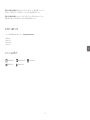
For assistance please contact: http://support.ekwb.com/
EKWB d.o.o.
Pod lipami 18
1218 Komenda
Slovenia – EU
8. SUPPORT AND SERVICE
EKWaterBlocks @EKWaterBlocks ekwaterblocks
ekwaterblocks
EKWBoffi cial
9. SOCIAL MEDIA
Eye exposure to thermal paste: Flush out thoroughly with running water for a minimum of 15
minutes. If irritation persists, seek professional medical attention.
Inhalation of thermal paste: If adverse effects occur, proceed to an uncontaminated area. If
breathing has been arrested, provide artifi cial respiration immediately. Seek immediate medical
attention.
Ingestion of thermal paste: Drink 2 large glasses of water. Do not induce vomiting. If a large
amount has been ingested, or if discomfort persists, obtain professional medical attention.

PRIROČNIK ZA NAMESTITEV
EKNucleus AIO
CR360 Dark / CR240 Dark
Združljiv s:
procesorji 1200/1700/20xx s podnožjem Intel 115X,
procesorjem AM4/AM5 s podnožjem AMD.
Za zagotovitev varne in enostavne namestitve natančno
preberite ta priročnik pred začetkom postopka namestitve.

- 15 -
VSEBINA
1. VARNOSTNI UKREPI 16
2. SPECIFIKACIJE 16
3. VKLJUČENO V TEM PAKIRANJU 17
ŠKATLA Z DODATNO OPREMO 17
4. NAMESTITEV PODNOŽJE INTEL LGA 115X/1200/1700 18
1. KORAK: ODSTRANITEV MATIČNE PLOŠČE 18
2. KORAK: NAMESTITEV HRBTNE PLOŠČE NA MATIČNO PLOŠČO 18
3. KORAK: S PRITRDILNIMI VIJAKI 18
4. KORAK: NAMESTITEV VENTILATORJEV NA HLADILNIK 18
5. KORAK: ODSTRANITEV ZAŠČITNEGA POKROVA HLADILNE PLOŠČE 18
6. KORAK: NAMESTITEV NOSILNE KONZOLE 18
7. KORAK: NAMESTITEV ENOTE ČRPALKE 18
8. KORAK: NAMESTITEV SKLOPA VENTILATORJA IN HLADILNIKA V OHIŠJE RAČUNALNIKA 19
9. KORAK: ČRPALKA – POVEZOVALNI KABEL 19
10. KORAK: VENTILATORJI – POVEZOVALNI KABLI 20
11. KORAK: USMERJENOST ZGORNJEGA DELA ČRPALKE 21
IZBIRNI KORAK! NANAŠANJE TERMIČNE SPOJINE 21
5. NAMESTITEV PODNOŽJE INTEL LGA 20XX 21
1. KORAK: NAMESTITEV PRITRDILNIH VIJAKOV (LGA 20XX) 21
6. NAMESTITEV PODNOŽJE AMD AM4/AM5 21
1. KORAK: ODSTRANITEV ORIGINALNIH PLASTIČNIH PRITRDILNIH SPONK (AMD) 21
2. KORAK: NAMESTITEV PRITRDILNIH VIJAKOV (AMD) 21
3. KORAK: NAMESTITEV VENTILATORJEV NA HLADILNIK (AMD) 21
4. KORAK: ODSTRANITEV ZAŠČITNEGA POKROVA HLADILNE PLOŠČE (AMD) 22
5. KORAK: NAMESTITEV NOSILNE KONZOLE (AMD) 22
6. KORAK: NAMESTITEV ENOTE ČRPALKE (AMD) 22
7. KORAK: NAMESTITEV SKLOPA VENTILATORJA IN HLADILNIKA V OHIŠJE RAČUNALNIKA (AMD) 22
8. KORAK: ČRPALKA – POVEZOVALNI KABLI (AMD) 23
9. KORAK: VENTILATORJI – POVEZOVALNI KABLI (AMD) 23
10. KORAK: USMERJENOST ZGORNJEGA DELA ČRPALKE (AMD) 24
IZBIRNI KORAK! NANAŠANJE TERMIČNE SPOJINE 24
7. SPLOŠNA VARNOSTNA OPOZORILA 24
8. PODPORA IN STORITVE 25
9. DRUŽBENA OMREŽJA 25

- 16 -
Za pravilno namestitev upoštevajte navodila v tem priročniku. Neustrezna namestitev lahko povzroči
škodo na vaši opremi. Podjetje EK Water Blocks ne prevzema nobene odgovornosti, izrecne ali
implicitne, za uporabo teh izdelkov in njihovo namestitev. Spodnja navodila se lahko spremenijo brez
predhodnega obvestila. Za posodobitve obiščite našo spletno stran www.ekwb.com.
1. VARNOSTNI UKREPI
1. Izdelek hranite zunaj dosega otrok.
2. Pred namestitvijo preverite seznam komponent in stanje izdelka. V primeru težav se obrnite na
prodajalno, v kateri ste kupili izdelek, da se dogovorite za zamenjavo ali vračilo kupnine.
3. Podjetje EKWB d.o.o. ne odgovarja za kakršno koli škodo, nastalo zaradi zunanjih vzrokov, kar med
drugim vključuje nepravilno uporabo, težave z električnim napajanjem, nesrečo, malomarnost,
spreminjanje, popravila, nepravilno namestitev in nepravilno testiranje.
4. Procesor in matična plošča se lahko poškodujeta, če je izdelek nameščen nepravilno.
5. Čezmerna sila na ventilator lahko poškoduje ventilator in/ali sistem.
6. Ta izdelek je komplet za vodno hlajenje procesorja, sestavljen iz posameznih originalnih delov
EKWB. Kombiniranje te enote za vodno hlajenje z deli, ki niso izdelki podjetja EK Water Blocks,
lahko povzroči izgubo garancije.
7. Oblika in specifi kacije izdelkov se lahko spremenijo za izboljšanje kakovosti in delovanja.
8. Črpalke ne smete zagnati z manj kot 20 % vrtilne frekvence. Črpalka mora ves čas ostati v
obratovalnem ciklu 20–100 % pulznoširinske modulacije. Priporočamo, da črpalka vedno obratuje
na 100 %. (Za pomoč pri nadzoru PWM si oglejte navodila za uporabo vaše matične plošče.)
2. SPECIFIKACIJE
Model EK-Nucleus AIO CR240 Dark EK-Nucleus AIO CR360 Dark
Hladilnik Mere 277 × 120 × 27 mm 400 × 398 × 120 × 27 mm
Material lamel Al Al
Ventilator
Mere 120 × 120 × 25 mm (2x) 120 × 120 × 25 mm (3x)
Hitrost
550–2300 ±10 % vrtilne frekvence
(pulznoširinska modulacija: 20–100 %)
550–2300 ±10 % vrtilne frekvence
(pulznoširinska modulacija: 20–100 %)
Zračni pretok 72 cfm 72 cfm
Življenjska doba 70.000 ur 70.000 ur
Raven hrupa 36 dB 36 dB
Vrsta ležaja Ležaj FDB Ležaj FDB
Vezni element za ventilator
4 kontakti 4 kontakti
Nazivna napetost ventilatorja
12 V 12 V
Črpalka
Mere (mm) 82,3 × 69,2 x 61,6 mm 82,3 × 69,2 x 61,6 mm
Vrtilna frekvenca
3100 vrt./min ± 10 % (pulznoširinska
modulacija: 20–100 %)
3100 vrt./min ± 10 % (pulznoširinska
modulacija: 20–100 %)
Življenjska doba 70.000 ur 70.000 ur
Raven hrupa 18,5 dB 18,5 dB
Vhodni tok 0,37 ± 10 % A 0,37 ± 10 % A

- 17 -
3. VKLJUČENO V TEM PAKIRANJU
V e n t i l a t o r E K - F P T F A N 1 2 0 E R F u l l P r e s s u r e T e c h n o l o g y
(2x/3x – število ventilatorjev je odvisno od različice sistema AIO)
EK-Nucleus AIO CR240 Dark /
EK-Nucleus AIO CR360 Dark
(1x)
ŠKATLA Z DODATNO OPREMO
Vijak z glavo Phillips
UNC 6–32 x 30 mm
(dolžina navoja 4 mm)
8x/12x
Vijak z glavo Phillips
UNC 6–32 x 34 mm
8x/12x
Vijak z glavo Phillips
UNC 6–32 x 6 mm
8x/12x
Matica za pritrditev z glavo
Phillips M3 x 4 mm
(za namestitev nosilnih konzol)
4x
Vijak za pritrditev na podnožje
Intel LGA 115x/LGA1200/
LGA1700/AMD AM4/AM5
4x
Vijak za pritrditev na podnožje
Intel LGA 20XX
4x
Matica (Intel/AMD)
4x
Vzmet
4x
Hrbtna plošča Intel
LGA 115x/1200
1x
Nosilna konzola Intel
1x
Hrbtna plošča Intel
LGA 1700
1x
Nosilna konzola AMD
1x
Podaljševalni kabel 500 mm
Škatla z dodatno opremo
(1x)
Uporabniški priročnik
(1x)
Tuba termalne paste
1x
Orodje za pritrdilne vijake
1x
INSTALLATION MANUAL
EKNucleus AIO
CR360 Dark / CR240 Dark
Compatible with:
Intel Socket 115X/1200/1700/20xx CPUs
AMD Socket AM4/AM5 CPUs
To ensure safe and easy installation, please carefully read
this manual before beginning the installation process!
1st Revision

- 18 -
4. NAMESTITEV PODNOŽJE INTEL LGA 115X/1200/1700
1. KORAK: ODSTRANITEV MATIČNE
PLOŠČE
Če ohišje vašega računalnika nima izreza na
spodnji strani procesorja na matični plošči,
je treba najprej odstraniti matično ploščo z
računalnika.
2. KORAK: NAMESTITEV HRBTNE
PLOŠČE NA MATIČNO PLOŠČO
Namestite hrbtno ploščo Intel za podnožje
LGA 115x/1200/1700 na hrbtno stran matične
plošče. Izberite ustrezno hrbtno ploščo glede
na nabor vezij, ki ga uporabljate. Poravnajte
odprtine matične plošče z odprtinami hrbtne
plošče.
Hrbtna plošča za Intel
LGA 115x/1200 ali 1700
3. KORAK: S PRITRDILNIMI VIJAKI
Namestite 4 pritrdilne palčne vijake skozi
matično ploščo na hrbtno ploščo. Pritrdilne
vijake lahko pri vijačite s pomočjo orodja za
pritrdile vijake. Ne uporabljajte drugih orodij, ker
lahko poškodujete matično ploščo. (tj. klešče)
6. KORAK: NAMESTITEV NOSILNE
KONZOLE
Uporabite 4 vijake M3 x 4 za namestitev
konzole Intel na enoto črpalke.
Pazite, da se ne dotaknete ali poškodujete
predhodno nanesene termične spojine.
M3x4
Nosilna
konzola
Intel
4. KORAK: NAMESTITEV VENTILA-
TORJEV NA HLADILNIK
Namestite ventilatorje (2 ali 3 ... odvisno od različice
AIO) na hladilnik z vijaki UNC 6–32 × 30 mm.
UNC
6–32 x 30 mm
Ventilator
Hladilnik
5. KORAK: ODSTRANITEV
ZAŠČITNEGA POKROVA HLADILNE
PLOŠČE
Odstranite zaščitni pokrov na hrbtni strani
enote črpalke. Ta je nameščen zato, da prepreči
poškodbe hladilne plošče in predhodno
nanesene termične spojine na hladilni plošči.
Pri odstranjevanju zaščitnega pokrova
in nadaljnjem nameščanju pazite, da se
ne dotaknete ali poškodujete predhodno
nanesene termične spojine.
7. KORAK: NAMESTITEV ENOTE
ČRPALKE
Obrišite stično površino procesorja (z
neabrazivno krpo ali vatirano palčko, kot je
prikazano na sliki primera).
Enoto črpalke poravnajte s pritrdilnimi vijaki in
procesorjem, kot je prikazano na sliki.
Priložene tlačne vzmeti in matice namestite
na pritrdilne vijake (4x). Začnite pritrjevati dve
matici hkrati, po možnosti navzkrižno, in jih ne
privijte do konca, dokler niso vse delno privite.
Matica
Vzmet
Neabrazivna
tkanina IHS
Zaščitni pokrov
Predhodno
nanesena
toplotno
prevodna
spojina
Matica za pritrditev na
podnožje za Intel LGA
115x/1200/1700 in
vtičnica AMD
AM4/AM5
Orodje za pritrdilne vijake

- 19 -
9. KORAK: ČRPALKA – POVEZOVALNI
KABEL
KORAK A:
4-polni priključek PWM s črpalke priključite na
matično ploščo.
8. KORAK: NAMESTITEV SKLOPA
VENTILATORJA IN HLADILNIKA V
OHIŠJE RAČUNALNIKA
Sklop hladilnika in ventilatorja/-ev pritrdite na
ohišje računalnika z vijaki UNC 6–32 × 6 mm.
Hladilnik na vrhu (priporočeno)
Navpična namestitev hladilnika s cevmi na
dnu (priporočeno)
Nepriporočljiva navpična namestitev
hladilnika s cevmi na vrhu
Nepriporočljiva namestitev hladilnika na
dnu
4-polni
priključek
PWM
EK-AIO Nucleus 240
EK-AIO Nucleus 360
UNC 6-32 x 6 mm
(8x)
UNC 6-32 x 6 mm
(12x)

- 20 -
KORAK A:
4-polni priključek za ventilator s
podaljševalnega kabla priključite neposredno
na razdelilnik za ventilator procesorja na
matični plošči. Vedno uporabite razdelilnik za
ventilator procesorja, kadar je to mogoče.
10. KORAK: VENTILATORJI –
POVEZOVALNI KABLI
Priključek za
ventilator
Moški priključek
Ženski priključek
KORAK B:
Povežite ženski priključek s podaljševalnega
kabla na moški priključek s prvega ventilatorja
v liniji.
Bodite pozorni, da ustrezno obrnete priključek
Micro-Fit.
KORAK C:
Pri različicah EK-Nucleus AIO CR240 in
EK-Nucleus AIO CR360 povežite drugi in
tretji ventilator zaporedoma z »marjetičnim
povezovanjem«.
Bodite pozorni, da ustrezno obrnete priključek.
Priključek za ventilator
Ženski priključek
Moški priključek
Ženski priključek
Moški
priključek
Ženski
priključek

- 21 -
5. NAMESTITEV PODNOŽJE INTEL LGA 20XX
1. KORAK: NAMESTITEV PRI-
TRDILNIH VIJAKOV (LGA 20XX)
Matične plošče podnožja LGA 20xx
(2066/2011 V3 /2011) ne zahtevajo
namestitve hrbtne plošče. Namestite 4
pritrdilne palčne vijake LGA 20XX v navojne
čepe M4 na vgrajenem zaklepnem mehanizmu
podnožja LGA 20XX (ILM). Pritrdilne vijake
lahko pri vijačite s pomočjo orodja za pritrdile
vijake. Ne uporabljajte drugih orodij, ker lahko
poškodujete matično ploščo. (tj. klešče)
Nadaljujte z namestitvijo tako,
da sledite navodilom iz četrtega
koraka na strani 18!
IZBIRNI KORAK! NANAŠANJE
TERMIČNE SPOJINE
Ta korak je pomemben samo v primeru druge
namestitve sistema AIO ali če ste poškodovali
predhodno nameščeno pasto na hrbtni strani
enote črpalke. Pri prvi namestitvi vam ni treba
nanesti dodatne termične spojine na stično
površino procesorja.
Obrišite stično površino procesorja (z
neabrazivno krpo ali vatirano palčko, kot je
prikazano na sliki primera). Na čista hladilna
rebra nanesite linijo termične spojine in jo s
kreditno kartico ali podobnim predmetom
nanesite po vseh hladilnih rebrih procesorja
(IHS).
12 34
6. NAMESTITEV PODNOŽJE AMD AM4/AM5
1. KORAK: ODSTRANITEV
ORIGINALNIH PLASTIČNIH
PRITRDILNIH SPONK (AMD)
S križnim izvijačem odstranite štiri vijake
UNC 6-32, ki pritrjujejo originalne plastične
pritrdilne sponke okrog podnožja, kot je
prikazano na skici. Obdržite originalno
hrbtno ploščo AMD® in odstranite pritrdilne
sponke ter jih shranite. Glejte sliko za nadaljnje
prepoznavanje delov.
2. KORAK: NAMESTITEV
PRITRDILNIH VIJAKOV (AMD)
Namestite 4 pritrdilne palčne vijake za
podnožje AMD AM4/AM5 na matično ploščo.
Pritrdilne vijake lahko pri vijačite s pomočjo
orodja za pritrdile vijake. Ne uporabljajte
drugih orodij, ker lahko poškodujete matično
ploščo. (tj. klešče)
Pritrdilne
sponke
Vijaki UNC 6-32
3. KORAK: NAMESTITEV VENTILA-
TORJEV NA HLADILNIK (AMD)
Namestite ventilatorje (2 ali 3 ... odvisno od različice
AIO) na hladilnik z vijaki UNC 6–32 × 30 mm.
11. KORAK: USMERJENOST
ZGORNJEGA DELA ČRPALKE
Dvignite zgornji del in ga vrtite, dokler ni logotip
EK ustrezno obrnjen, nato ga spustite nazaj.
Magneti bodo zadržali zgornji del na mestu.
Čestitamo! Uspešno ste namestili hladilni
sistem EK-Nucleus AIO.
Neabrazivna
tkanina
IHS
LGA 20XX M3,5
Vijak
Matica za pritrditev
na podnožje za Intel
LGA 115x/1200/1700
in vtičnica AMD
AM4/AM5
Orodje za pritrdilne vijake
Orodje za pritrdilne vijake
UNC
6-32 x 30 mm
Ventilator
Hladilnik
A página está carregando...
A página está carregando...
A página está carregando...
A página está carregando...
A página está carregando...
A página está carregando...
A página está carregando...
A página está carregando...
A página está carregando...
A página está carregando...
A página está carregando...
A página está carregando...
A página está carregando...
A página está carregando...
A página está carregando...
A página está carregando...
A página está carregando...
A página está carregando...
A página está carregando...
A página está carregando...
A página está carregando...
A página está carregando...
A página está carregando...
A página está carregando...
A página está carregando...
A página está carregando...
A página está carregando...
A página está carregando...
A página está carregando...
A página está carregando...
A página está carregando...
A página está carregando...
A página está carregando...
A página está carregando...
A página está carregando...
A página está carregando...
A página está carregando...
A página está carregando...
A página está carregando...
A página está carregando...
A página está carregando...
A página está carregando...
A página está carregando...
A página está carregando...
A página está carregando...
A página está carregando...
A página está carregando...
A página está carregando...
A página está carregando...
A página está carregando...
A página está carregando...
A página está carregando...
A página está carregando...
A página está carregando...
A página está carregando...
A página está carregando...
A página está carregando...
A página está carregando...
A página está carregando...
A página está carregando...
A página está carregando...
A página está carregando...
A página está carregando...
A página está carregando...
A página está carregando...
A página está carregando...
A página está carregando...
A página está carregando...
A página está carregando...
A página está carregando...
A página está carregando...
A página está carregando...
A página está carregando...
A página está carregando...
A página está carregando...
A página está carregando...
A página está carregando...
A página está carregando...
A página está carregando...
A página está carregando...
A página está carregando...
A página está carregando...
A página está carregando...
A página está carregando...
A página está carregando...
A página está carregando...
A página está carregando...
A página está carregando...
A página está carregando...
A página está carregando...
-
 1
1
-
 2
2
-
 3
3
-
 4
4
-
 5
5
-
 6
6
-
 7
7
-
 8
8
-
 9
9
-
 10
10
-
 11
11
-
 12
12
-
 13
13
-
 14
14
-
 15
15
-
 16
16
-
 17
17
-
 18
18
-
 19
19
-
 20
20
-
 21
21
-
 22
22
-
 23
23
-
 24
24
-
 25
25
-
 26
26
-
 27
27
-
 28
28
-
 29
29
-
 30
30
-
 31
31
-
 32
32
-
 33
33
-
 34
34
-
 35
35
-
 36
36
-
 37
37
-
 38
38
-
 39
39
-
 40
40
-
 41
41
-
 42
42
-
 43
43
-
 44
44
-
 45
45
-
 46
46
-
 47
47
-
 48
48
-
 49
49
-
 50
50
-
 51
51
-
 52
52
-
 53
53
-
 54
54
-
 55
55
-
 56
56
-
 57
57
-
 58
58
-
 59
59
-
 60
60
-
 61
61
-
 62
62
-
 63
63
-
 64
64
-
 65
65
-
 66
66
-
 67
67
-
 68
68
-
 69
69
-
 70
70
-
 71
71
-
 72
72
-
 73
73
-
 74
74
-
 75
75
-
 76
76
-
 77
77
-
 78
78
-
 79
79
-
 80
80
-
 81
81
-
 82
82
-
 83
83
-
 84
84
-
 85
85
-
 86
86
-
 87
87
-
 88
88
-
 89
89
-
 90
90
-
 91
91
-
 92
92
-
 93
93
-
 94
94
-
 95
95
-
 96
96
-
 97
97
-
 98
98
-
 99
99
-
 100
100
-
 101
101
-
 102
102
-
 103
103
-
 104
104
-
 105
105
-
 106
106
-
 107
107
-
 108
108
-
 109
109
-
 110
110


ekwb EK-Nucleus AIO CR360 Dark Guia de instalação
- Tipo
- Guia de instalação
em outras línguas
Artigos relacionados


Outros documentos
-
Corsair H60x RGB Elite Performance Liquid CPU Cooler Manual do usuário
-
NZXT Kraken 240 Manual do usuário
-
-
Corsair iCUE H100i Series Manual do usuário
-
-
-
Asus ROG RYUJIN 240 Guia de usuario