
INSTALLATION MANUAL
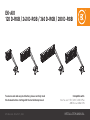
EKAIO
120 D-RGB / 240 D-RGB / 360 D-RGB / 280 D-RGB
Compatible with:
Intel Socket 115X / 1200 / 20XX CPUs
AMD Socket AM4 CPU
To ensure safe and easy installation, please carefully read
this manual before starting with the installation process!
4th Revision - March 17, 2021

INFORMATION TO THE USER
This equipment has been tested and found to comply with the limits for a class B digital
device, pursuant to part 15 of the FCC Rules. These limits are designed to provide reasonable
protection against harmful interference in a residential installation. This equipment generates,
uses and can radiate radio frequency energy and if not installed and used in accordance with
the instructions, may cause harmful interference to radio communications. However, there is
no guarantee that interference will not occur in a particular installation. If this equipment does
cause harmful interference to radio or television reception, which can be determined by turning
the equipment off and on, the user is encouraged to try to correct the interference by one or
more of the following measures:
• Reorient or relocate the receiving antenna.
• Increase the separation between the equipment and receiver.
• Connect the equipment into an outlet on a circuit different from that to which the receiver
is connected.
• Consult the dealer or an experienced radio/TV technician for help.
The user is cautioned that changes and modifi cations made to the equipment without the approval
of manufacturer could void the user’s authority to operate this equipment.

1. SAFETY PRECAUTIONS 4
2. SPECIFICATIONS 4
3. ENCLOSED IN THIS PACKAGE 5
MOUNTING KIT 5
4. INSTALLATION – INTEL LGA-115X/1200 SOCKET 6
STEP 1: REMOVING THE MOTHERBOARD 6
STEP 2: ATTACHING THE BACKPLATE TO THE MOTHERBOARD 6
STEP 3: ATTACHING MOUNTING SCREWS 6
STEP 4: INSTALLING THE FANS TO THE RADIATOR 6
STEP 5: REMOVING THE COLD-PLATE PROTECTIVE COVER 6
STEP 6: MOUNTING BRACKETS INSTALLATION 6
STEP 7: PUMP UNIT INSTALLATION 6
STEP 8: INSTALLING THE RADIATOR AND FANS ASSEMBLY INTO THE PC CASE 7
STEP 9: PUMP – CONNECTING CABLES 7
STEP 10: FANS – CONNECTING CABLES 8
OPTIONAL STEP! APPLYING THE THERMAL COMPOUND 8
5. INSTALLATION – INTEL LGA-20XX SOCKET 8
STEP 1: ATTACHING MOUNTING SCREWS (LGA-20XX) 8
6. INSTALLATION – AMD AM4 SOCKET 9
STEP 1: REMOVING THE ORIGINAL PLASTIC HOLD-DOWN CLAMPS (AMD) 9
STEP 2: ATTACHING MOUNTING SCREWS (AMD) 9
STEP 3: INSTALLING THE FANS TO THE RADIATOR (AMD) 9
STEP 4: REMOVING THE COLD-PLATE PROTECTIVE COVER (AMD) 9
STEP 5: MOUNTING BRACKETS INSTALLATION (AMD) 9
STEP 6: PUMP UNIT INSTALLATION (AMD) 9
STEP 7: INSTALLING THE RADIATOR AND FANS ASSEMBLY INTO THE PC CASE (AMD) 10
STEP 8: PUMP – CONNECTING CABLES (AMD) 10
STEP 9: FANS – CONNECTING CABLES (AMD) 11
OPTIONAL STEP! APPLYING THE THERMAL COMPOUND 11
7. SUPPORT AND SERVICE 11
8. SOCIAL MEDIA 11
TABLE OF CONTENT

- 4 -
This product is intended for installation by expert users only. Please, consult with a qualifi ed
technician. Improper installation may result in damage to your equipment. EK Water Blocks
assumes no liability whatsoever, expressed or implied, for the use of these products or their
installation. The following instructions are subject to change without notice. Please visit our web
site at www.ekwb.com for updates.
1. SAFETY PRECAUTIONS
1. Keep and store the product away from the reach of children.
2. Check the component list and condition of the product before installation. If you encounter a
problem, contact the shop where you have purchased the product to get a replacement or a refund.
3. EKWB d.o.o. is not responsible for any damages due to external causes, including but not
limited to: improper use, problems with electrical power, accident, neglect, alteration, repair,
improper installation, and improper testing.
4. CPU and motherboard are subject to damage if the product is incorrectly installed.
5. The excessive force exerted on the fan may cause damage to the fan and/or system.
6. This product is a CPU liquid cooling solution kit, comprising of individual original EKWB parts.
Combining this liquid cooling unit with parts, other than EK Water Block products, may lead to
warranty loss.
7. Product design and specifi cations may be revised to improve quality and performance.
8. You must not run the pump below 20% RPM. The pump must stay within a 20-100% PWM
duty cycle at all times. We recommend to always run the pump at 100%.
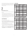
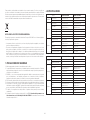
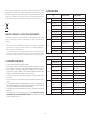
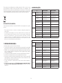
Model EK-AIO 360 D-RGB EK-AIO 280 D-RGB
Radiator Dimensions 397x120x27 mm 313x140x27 mm
Fin material Al Al
Fan
Dimensions 120x120x25 mm (3x) 140x140x25 mm (2x)
Speed 600-2200 RPM ±10%
(PWM: 25-100%)
500-2000 RPM +-10%
(PWM: 25-100%)
Life Expectancy 50,000 hours 50,000 hours
Bearing Type Fluid Dynamic bearing (FDB) Fluid Dynamic bearing (FDB)
Connector 4-Pin 4-Pin
Rated Voltage 12V 12V
Pump
Dimensions (mm) 88x70x53 mm 88x70x53 mm
RPM 850-2600 RPM ±10%
(PWM: 20-100%)
850-2600 RPM ±10%
(PWM: 20-100%)
Life Expectancy 50,000 hours 50,000 hours
Noise Level 23 dB 23 dB
Input Current 0.65 ±10% A 0.65 ±10% A
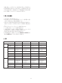
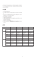
2. SPECIFICATIONS
Model EK-AIO 120 D-RGB EK-AIO 240 D-RGB
Radiator Dimensions 157x120x27 mm 277x120x27 mm
Fin material Al Al
Fan
Dimensions 120x120x25 mm 120x120x25 mm (2x)
Speed 600-2200 RPM ±10%
(PWM: 25-100%)
600-2200 RPM ±10%
(PWM: 25-100%)
Life Expectancy 50,000 hours 50,000 hours
Bearing Type Fluid Dynamic bearing (FDB) Fluid Dynamic bearing (FDB)
Connector 4-Pin 4-Pin
Rated Voltage 12V 12V
Pump
Dimensions (mm) 88x70x53 mm 88x70x53 mm
RPM 850-2600 RPM ± 10%
(PWM: 20-100%)
850-2600 RPM ±10%
(PWM: 20-100%)
Life Expectancy 50,000 hours 50,000 hours
Noise Level 23 dB 23 dB
Input Current 0.65 ±10% A 0.65 ±10% A
NOTE ON ENVIRONMENTAL PROTECTION:
After the implementation of the European Directive 2012/19/EU in the national legal system, the
following applies:
• Electrical and electronic devices may not be disposed of with domestic waste.
• Consumers are obliged by law to return electrical and electronic devices at the end of their
service lives to the public collecting points set up for this purpose or point of sale. Details to
this are defi ned by the national law of the respective country. This symbol on the product, the
instruction manual or the package indicates that a product is subject to these regulations.
By recycling, reusing the materials or other forms of utilising old devices, you are making an
important contribution to protecting our environment.

- 5 -
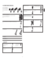
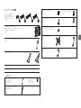
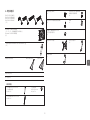
3. ENCLOSED IN THIS PACKAGE
EK-Vardar S 120ER D-RGB Fan
(1x / 2x / 3x – number of fans depends on the AIO version) /
EK-Vardar S 140ER D-RGB Fan
(2x)
EK-AIO 120 D-RGB unit /
EK-AIO 240 D-RGB unit /
EK-AIO 360 D-RGB unit /
EK-AIO 280 D-RGB unit
(1x)
A tube of Thermal Paste (3830046998446 - EK-TIM Ectotherm (1g))
(1x)
Fan Cable Y-splitter
Mounting Kit (1x)
User Manual (1x)
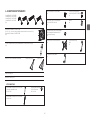
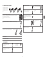
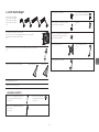
MOUNTING KIT
Phillips Head Screw UNC 6-32 x 30 mm
(5 mm thread length)
4x / 8x / 12x
Phillips Head Screw UNC 6-32 x 34 mm
4x / 8x / 12x
Phillips Head Screw
UNC 6-32 x 6 mm
4x / 8x / 12x
Thumb nut (Intel /AMD)
4x
Mounting thumb screw for Intel LGA
20XX socket
4x
Mounting thumb screw for INTEL
LGA 115x / AMD AM4 socket
4x
Mounting Plate Phillips Head
M4 x 4 mm (for the installation
of mounting brackets)
4x
Spring
4x
Intel LGA 115x Backplate
1x
AMD mounting bracket
2x
Intel mounting bracket
2x
EK-AIO 240 / 280 EK-AIO 360

- 6 -
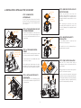
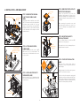
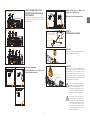
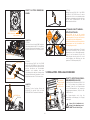
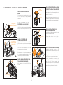
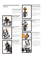
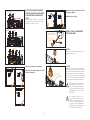
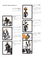
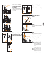
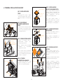
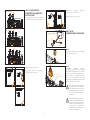
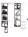
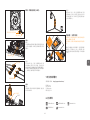
4. INSTALLATION INTEL LGA115X/1200 SOCKET
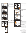
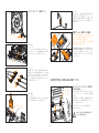
STEP 1: REMOVING THE
MOTHERBOARD
If your PC case doesn't have a cutout from the
bottom CPU side of the motherboard, you will
fi rst need to remove the motherboard from
your computer.
STEP 2: ATTACHING THE BACKPLATE
TO THE MOTHERBOARD
Install the Intel backplate for LGA-115x socket
to the back of your motherboard. Align the
holes on the motherboard with the holes on
the backplate.
Intel LGA 115x
Backplate
STEP 3: ATTACHING MOUNTING
SCREWS
Install 4x LGA-115x mounting thumb screws
through your motherboard to the backplate.
Thumb screws are to be installed without the
use of tools (i.e. pliers).
Start fastening two thumb screws at a time,
preferably in a cross pattern, but do not tighten
them fully until all four are partially screwed in.
Mounting thumb
screw for INTEL
LGA 115x / AMD
AM4 socket
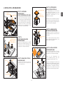
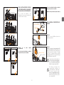
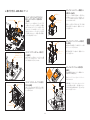
STEP 6: MOUNTING BRACKETS
INSTALLATION
Use four M4x4 screws to install two Intel
brackets onto the pump unit.
Be careful not to touch or damage the pre-
applied thermal compound!
M4x4
Intel
Mounting
Bracket
STEP 4: INSTALLING THE FANS TO
THE RADIATOR
Attach the fans (1x, 2x or 3x, depending on the
AIO version) to the radiator using the UNC 6-32
x 30mm screws.
UNC
6-32 x 30 mm
Fan Radiator
STEP 5: REMOVING THE COLD-PLATE
PROTECTIVE COVER
Remove the protective cover from the
backside of the pump unit. It is there only to
prevent the damage of the cold-plate and the
pre-applied thermal compound that is on the
cold-plate.
When removing the protective cover and
proceeding with installation be careful not
to touch or damage the pre-applied thermal
compound!
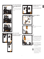
STEP 7: PUMP UNIT INSTALLATION
Wipe the CPU’s contact surface (using a
non-abrasive cloth pr a Q-tip as shown in the
sample image).
Align the pump unit over the mounting screws
and CPU as shown in the picture.
Place the enclosed compression springs and
thumb nuts over the mounting screws (4x). Start
fastening two thumb nuts at a time, preferably
in cross pattern, and do not tighten them fully
until all of them are partially screwed in.
Thumb Nut
Spring
Non-abrasive
cloth IHS
Protective
Cover
Pre-applied
thermal
Compound

- 7 -
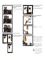
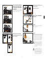
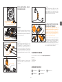
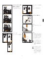
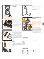
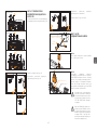
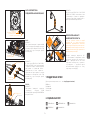
STEP 9: PUMP – CONNECTING
CABLES
D-RGB
Connector
VDG Connector
4-pin Connector
STEP A:
Plug the 4-pin PWM connector of the pump to
the motherboard.
D-RGB Header
RGB Header
STEP B:
Plug the 3-pin connector of the pump’s D-RGB LED
light to the D-RGB HEADER on the motherboard.
The LED will work if the pin layout on the header is
as follows: +5V, Digital, Empty, Ground. With some
motherboards, you can alternatively use a VDG
connector instead of a D-RGB to connect the LED.
Please ensure that the arrow indicated on
the connector is plugged into the +5V line
as indicated on your motherboard. If you
put LED Diode to the 12V RGB HEADER
you can damage the LEDs.
Connector is the same on D-RGB and RGB
versions, but D-RGB version has 3 cables
from connector to PCB; RGB version has
4 cables. If you connect D-RGB led to
ordinary RGB header you can damage
your motherboard or LED strip.
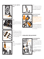
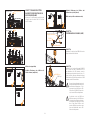
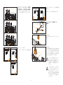
STEP 8: INSTALLING THE RADIATOR
AND FANS ASSEMBLY INTO THE PC
CASE
Attach the assembly of the radiator and the
fan(-s) to the PC case with the UNC 6-32 x
6mm screws.
EK-AIO 120 D-RGB
EK-AIO 240 D-RGB /
EK-AIO 280 D-RGB
EK-AIO 360 D-RGB
UNC 6-32 x 6 mm
(4x)
UNC 6-32 x 6 mm
(8x)
UNC 6-32 x 6 mm
(12x)
Radiator on top (recommended)
Vertical placement of the radiator with
tubing at the bottom (recommended)
Vertical placement of the radiator with
tubing at the top (not optimal)
Radiator at the bottom (should be avoided)

- 8 -
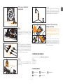
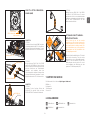
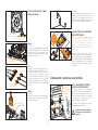
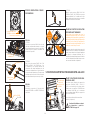
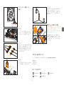
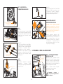
STEP 10: FANS – CONNECTING
CABLES
Fan D-RGB LED Light
Connector
Fan Connector
STEP A:
OPTION 1:
Connect the 4-pin PWM connector from the
fan cable directly to the CPU fan-header on the
motherboard. Always use the CPU fan-header
if possible.
OPTION 2:
In the case of EK-AIO 240 / 280 D-RGB and EK-
AIO 360 D-RGB versions (with 2 or 3 fans), you
may connect the connectors from each of the
fans with the connectors on the Y-splitter cable
and then connect the Y-splitter connector to
the fan-header on the motherboard. Always
use the CPU fan-header if possible.
Y-splitter
Fan Connector
STEP B:
OPTION 1:
Plug the 3-pin connector for D-RGB LED light
of the fan(-s) to the D-RGB HEADER on the
motherboard.
D-RGB Header
RGB Header
OPTION 2:
In the case of EK-AIO 240 / 280 D-RGB and
EK-AIO 360 D-RGB versions, you may fi rst
connect 2 or 3 fans together in a “daisy-chain”
connection and then connect them all together
to a D-RGB header on the motherboard.
5. INSTALLATION INTEL LGA20XX SOCKET
STEP 1: ATTACHING MOUNTING
SCREWS (LGA-20XX)
LGA-20xx (2066 / 2011 V3 / 2011) socket
motherboards do not require backplate
installation. Install 4x LGA-20XX mounting
thumb screws into M4 threaded stubs on the
integrated latch mechanism (ILM) of the LGA-
20XX socket.
Thumb screws are to be installed without the
use of tools (i.e. pliers).
Continue installation by following
the instructions from Step 4 on
page 6
OPTIONAL STEP! APPLYING THE
THERMAL COMPOUND
This step is relevant only in the case of a
second installation of AIO or if you have
damaged the pre-applied paste on the
backside of the pump unit! For the fi rst
installation, you don’t need to apply the
additional thermal compound to the CPU’s
contact surface!
Wipe the CPU’s contact surface (using a
non-abrasive cloth or a Q-tip as shown in the
sample image). On a clean IHS, apply a line
of thermal compound and spread it over the
whole CPU heat spreader (IHS) with a credit
card or something similar.
Non-abrasive
cloth IHS
Fan
Connector
LGA-2011 M3
Thumb Screw

- 9 -
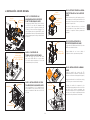
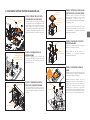
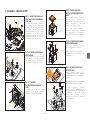
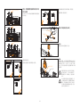
6. INSTALLATION AMD AM4 SOCKET
STEP 1: REMOVING THE ORIGINAL
PLASTIC HOLD-DOWN CLAMPS
(AMD)
Using Philips-head screwdriver, remove the 4
UNC 6-32 screws securing the original plastic
hold-down clamps around the socket as
shown in the image. Keep the original AMD®
backplate and remove the hold-down clamps
to store them away. See the image for further
part identifi cation.
STEP 2: ATTACHING MOUNTING
SCREWS (AMD)
Install 4x mounting thumb screw for AMD
AM4 socket onto your motherboard. The
screws are to be installed without the use of
tools (i.e. pliers).
Mounting thumb
screw for INTEL
LGA 115x / AMD
AM4 socket
Hold-down
clamps
UNC 6-32 Screws
STEP 3: INSTALLING THE FANS TO
THE RADIATOR (AMD)
Attach the fans (1x, 2x or 3x, depending on the
AIO version) to the radiator with the UNC 6-32
x 30mm screws.
UNC
6-32 x 30 mm
Fan Radiator
STEP 5: MOUNTING BRACKETS
INSTALLATION (AMD)
Use four M4x4 screws to install two AMD
brackets onto the pump unit.
Be careful not to touch or damage the pre-
applied thermal compound!
M4x4
AMD
Mounting
Bracket
STEP 4: REMOVING THE COLD-PLATE
PROTECTIVE COVER (AMD)
Remove the protective cover from the
backside of the pump unit. It is there only to
prevent the damage of the cold-plate and the
pre-applied thermal compound that is on the
cold-plate.
When removing the protective cover and
proceeding with installation be careful not
to touch or damage the pre-applied thermal
compound!
STEP 6: PUMP UNIT INSTALLATION
(AMD)
Wipe the CPU’s contact surface (using a
non-abrasive cloth pr a Q-tip as shown in the
sample image).
Align the pump unit over the mounting screws
and CPU as shown in the picture.
Place the enclosed compression springs and
thumb nuts over the mounting screws (4x). Start
fastening two thumb nuts at a time, preferably
in cross pattern, and do not tighten them fully
until all of them are partially screwed in.
Thumb Nut
Spring
Non-abrasive
cloth IHS
Protective
Cover
Pre-applied
thermal
Compound

- 10 -
STEP 7: INSTALLING THE RADIATOR
AND FANS ASSEMBLY INTO THE PC
CASE (AMD)
Attach the assembly of the radiator and the
fan(-s) to the PC case with the UNC 6-32 x
6mm screws.
UNC 6-32 x 6 mm
(4x)
UNC 6-32 x 6 mm
(8x)
UNC 6-32 x 6 mm
(12x)
EK-AIO 120 D-RGB
EK-AIO 240 D-RGB /
EK-AIO 280 D-RGB
EK-AIO 360 D-RGB
STEP 8: PUMP – CONNECTING CA-
BLES (AMD)
D-RGB
Connector
VDG Connector
4-pin Connector
STEP A:
Plug the 4-pin PWM connector of the pump to
the motherboard.
D-RGB Header
RGB Header
STEP B:
Plug the 3-pin connector of the pump’s D-RGB LED
light to the D-RGB HEADER on the motherboard.
The LED will work if the pin layout on the header is
as follows: +5V, Digital, Empty, Ground. With some
motherboards, you can alternatively use a VDG
connector instead of a D-RGB to connect the LED.
Please ensure that the arrow indicated on
the connector is plugged into the +5V line
as indicated on your motherboard. If you
put LED Diode to the 12V RGB HEADER
you can damage the LEDs.
Connector is the same on D-RGB and RGB
versions, but D-RGB version has 3 cables
from connector to PCB; RGB version has
4 cables. If you connect D-RGB led to
ordinary RGB header you can damage
your motherboard or LED strip.
Radiator on top (recommended)
Vertical placement of the radiator with
tubing at the bottom (recommended)
Vertical placement of the radiator with
tubing at the top (not optimal)
Radiator at the bottom (should be avoided)

- 11 -
STEP 9: FANS – CONNECTING
CABLES (AMD)
Fan D-RGB LED Light
Connector
Fan Connector
STEP A:
OPTION 1:
Connect the 4-pin PWM connector of the fan
cable directly to the CPU fan-header on the
motherboard. Always use the CPU fan-header
if possible.
OPTION 2:
In the case of EK-AIO 240 / 280 D-RGB and EK-
AIO 360 D-RGB versions (with 2 or 3 fans), you
may connect the connectors from each of the
fans to the connectors on the Y-splitter cable
and then connect the Y-splitter connector to
the fan-header on the motherboard. Always
use the CPU fan-header if possible.
Y-splitter
Fan Connector
STEP B:
OPTION 1:
Plug the 3-pin connector for D-RGB LED light
of the fan(-s) to the D-RGB HEADER on the
motherboard.
D-RGB Header
RGB Header
OPTION 2:
In the case of EK-AIO 240 / 280 D-RGB and
EK-AIO 360 D-RGB versions, you may fi rst
connect 2 or 3 fans together in a “daisy-chain”
connection and then connect them all together
to a D-RGB header on the motherboard.
For assistance please contact: http://support.ekwb.com/
EKWB d.o.o.
Pod lipami 18
1218 Komenda
Slovenia - EU
7. SUPPORT AND SERVICE
EKWaterBlocks @EKWaterBlocks ekwaterblocks
ekwaterblocks
EKWBoffi cial
8. SOCIAL MEDIA
OPTIONAL STEP! APPLYING THE
THERMAL COMPOUND
This step is relevant only in the case of a
second installation of AIO or if you have
damaged the pre-applied paste on the
backside of the pump unit! For the fi rst
installation, you don’t need to apply the
additional thermal compound to the CPU’s
contact surface!
Wipe the CPU’s contact surface (using a
non-abrasive cloth or a Q-tip as shown in the
sample image). On a clean IHS, apply a line
of thermal compound and spread it over the
whole CPU heat spreader (IHS) with a credit
card or something similar.
Non-abrasive
cloth IHS
Fan
Connector

INSTALLATIONSHANDBUCH
Kompatibel mit:
Intel Buchse 115X / 20xx / 1200 CPUs
AMD Buchse AM4 CPU
Lesen Sie dieses Handbuch sorgfältig durch, bevor Sie mit
der Installation beginnen, um eine sichere und einfache
Installation zu gewährleisten!
EKAIO
120 D-RGB / 240 D-RGB / 360 D-RGB / 280 D-RGB

- 13 -
1. SICHERHEITSVORKEHRUNGEN 14
2. TECHNISCHE DATEN 14
3. IN DIESEM PAKET ENTHALTEN 15
MONTAGESATZ 15
4. INSTALLATION - INTEL LGA-115X/1200-BUCHSE 16
SCHRITT 1: ENTFERNEN DES MOTHERBOARDS 16
SCHRITT 2: BEFESTIGEN SIE DIE RÜCKWAND AM MOTHERBOARD 16
SCHRITT 3: BEFESTIGUNGSSCHRAUBEN ANBRINGEN 16
SCHRITT 4: EINBAU DER LÜFTER IN DEN KÜHLER 16
SCHRITT 5: ENTFERNEN DER KÜHLPLATTENSCHUTZFOLIE 16
SCHRITT 6: ANBRINGUNG VON MONTAGEHALTERUNGEN 16
SCHRITT 7: INSTALLATION DER PUMPENEINHEIT 16
SCHRITT 8: EINBAU DER LÜFTERBAUGRUPPE UND DES KÜHLERS IN EIN PCGEHÄUSE 17
SCHRITT 9: PUMPENANSCHLUSSKABEL 17
SCHRITT 10: LÜFTER - VERBINDUNGSKABEL 18
OPTIONALER SCHRITT!! WÄRMELEITPASTE AUFTRAGEN 18
5. INSTALLATION - INTEL LGA-20XX-BUCHSE 18
SCHRITT 1: BEFESTIGUNGSSCHRAUBEN ANBRINGEN (LGA-20XX) 18
6. INSTALLATION – AMD AM4 BUCHSE 19
SCHRITT 1: ENTFERNEN DER ORIGINALEN KUNSTSTOFFNIEDERHALTER (AMD) 19
SCHRITT 2: BEFESTIGUNGSSCHRAUBEN ANBRINGEN (AMD) 19
SCHRITT 3: EINBAU DER LÜFTER IN DEN KÜHLER (AMD) 19
SCHRITT 4: ENTFERNEN DER KÜHLPLATTENSCHUTZFOLIE 19
SCHRITT 5: ANBRINGUNG VON MONTAGEHALTERUNGEN (AMD) 19
SCHRITT 6: INSTALLATION DER PUMPENEINHEIT (AMD) 19
SCHRITT 7: EINBAU DER LÜFTERBAUGRUPPE UND DES KÜHLERS IN EIN PCGEHÄUSE (AMD) 20
SCHRITT 8: PUMPENANSCHLUSSKABEL (AMD) 20
SCHRITT 9: LÜFTER - VERBINDUNGSKABEL (AMD) 21
OPTIONALER SCHRITT!! WÄRMELEITPASTE AUFTRAGEN 21
7. SUPPORT UND SERVICE 21
8. SOZIALE MEDIEN 21
INHALT

- 14 -
Dieses Produkt ist nur für die Installation durch erfahrene Benutzer vorgesehen. Bitte wenden Sie sich
an einen qualifi zierten Techniker. Eine unsachgemäße Installation kann zu Schäden an Ihrem Gerät
führen. EK Water Blocks übernimmt keinerlei Haftung, weder ausdrücklich noch stillschweigend, für die
Verwendung dieser Produkte oder deren Installation. Die folgenden Anweisungen können ohne vorherige
Ankündigung geändert werden. Bitte besuchen Sie unsere Website unter www.ekwb.com für Updates.
1. SICHERHEITSVORKEHRUNGEN
1. Bewahren Sie das Produkt außerhalb der Reichweite von Kindern auf.
2. Überprüfen Sie vor der Installation die Komponentenliste und den Zustand des Produkts. Wenn Sie
auf ein Problem stoßen, wenden Sie sich an das Geschäft, in dem Sie das Produkt gekauft haben, um
Ersatz oder eine Rückerstattung zu erhalten.
3. EKWB d.o.o. haftet nicht für Schäden, die auf äußere Ursachen zurückzuführen sind, einschließlich,
aber nicht beschränkt auf: unsachgemäße Verwendung, Probleme mit der Stromversorgung, Unfall,
Nachlässigkeit, Änderung, Reparatur, unsachgemäße Installation und unsachgemäße Prüfung.
4. CPU und Motherboard können beschädigt werden, wenn das Produkt falsch installiert wird.
5. Wenn übermäßig Kraft auf den Lüfter ausgeübt wird, kann der Lüfter und/oder das System
beschädigt werden.
6. Bei diesem Produkt handelt es sich um ein CPU-Kit für die Flüssigkeitskühlung, das aus einzelnen
EKWB-Originalteilen besteht. Diese Flüssigkeitskühleinheit mit anderen Teilen als den EK Water
Block-Produkten zu kombinieren, kann zum Verlust der Garantie führen.
7. Produktdesign und -spezifi kationen können überarbeitet werden, um Qualität und Leistung zu
verbessern.
8. Die Pumpe nicht unter 20 % der U/Min. betreiben. Die Pumpe muss jederzeit innerhalb von
20–100 % des PWM-Betriebszyklus bleiben. Wir empfehlen, dass die Pumpe immer mit 100 %
betrieben wird.
2. TECHNISCHE DATEN
Modell EK-AIO 120 D-RGB EK-AIO 240 D-RGB
Kühler Abmessungen 157x120x27 mm 277x120x27 mm
Rippenmaterial Al Al
Lüfter
Abmessungen 120x120x25 mm 120x120x25 mm (2x)
Geschwindigkeit 600 - 2200 U/min ± 10 %
(PWM: 25 - 100 %)
600 - 2200 U/min ± 10 %
(PWM: 25 - 100 %)
Lebensdauer 50.000 Stunden 50.000 Stunden
Lagertyp Fluid Dynamic bearing (FDB) Fluid Dynamic bearing (FDB)
Verbindungsstück 4-polig 4-polig
Nennspannung 12V 12V
Pumpe
Abmessungen (mm)
88x70x53 mm 88x70x53 mm
U/min
850 - 2600 U/min ± 10 %
(PWM: 20 - 100 %)
850 - 2600 U/min ± 10 %
(PWM: 20 - 100 %)
Lebensdauer 50.000 Stunden 50.000 Stunden
Lärmpegel 23 dB 23 dB
Eingangsleistung 0.65 ±10% A 0.65 ±10% A
Modell EK-AIO 360 D-RGB EK-AIO 280 D-RGB
Kühler Abmessungen 397x120x27 mm 313x140x27 mm
Rippenmaterial Al Al
Lüfter
Abmessungen 120x120x25 mm (3x) 140x140x25 mm (2x)
Geschwindigkeit 600 - 2200 U/min ± 10 %
(PWM: 25 - 100 %)
500-2000 U/min ± 10 %
(PWM: 25 - 100 %)
Lebensdauer 50.000 Stunden 50.000 Stunden
Lagertyp Fluid Dynamic bearing (FDB) Fluid Dynamic bearing (FDB)
Verbindungsstück 4-polig 4-polig
Nennspannung 12V 12V
Pumpe
Abmessungen (mm)
88x70x53 mm 88x70x53 mm
U/min
850 - 2600 U/min ± 10 %
(PWM: 20 - 100 %)
850 - 2600 U/min ± 10 %
(PWM: 20 - 100 %)
Lebensdauer 50.000 Stunden 50.000 Stunden
Lärmpegel 23 dB 23 dB
Eingangsleistung 0.65 ±10% A 0.65 ±10% A
HINWEIS ZUM UMWELTSCHUTZ:
Ab dem Zeitpunkt der Umsetzung der europäischen Richtlinie 2012/19/EU in nationales Recht
gilt folgendes:
• Elektrische und elektronische Geräte dürfen nicht mit dem Hausmüll entsorgt werden.
• Der Verbraucher ist gesetzlich verpflichtet, elektrische und elektronisch Geräte am
Ende ihrer Lebensdauer an den dafür eingerichteten, ö-entlichen Sammelstellen oder an
die Verkaufstelle zurückzugeben. Einzelheiten dazu regelt das jeweilige Landesrecht.
Das Symbol auf dem Produkt, der Gebrauchsanleitung oder der Verpackung weist auf
diese Bestimmungen hin. Mit der Wiederverwertung, der stochen Verwertung oder
anderer Formen der Verwertung von Altgeräten leisten Sie einen wichtigen Beitrag zum
Schutz unserer Umwelt. In Deutschland gelten oben genannte Entsorgungsregeln, laut
Batterieverordnung, für Batterien und Akkus entsprechend.

- 15 -
3. IN DIESEM PAKET ENTHALTEN
EK-Vardar S 120ER D-RGB Lüfter
(1x / 2x / 3x – Anzahl der Lüfter hängt von der AIO-Version ab) /
EK-Vardar S 140ER D-RGB Lüfter
(2x)
EK-AIO 120 D-RGB Einheit /
EK-AIO 240 D-RGB Einheit /
EK-AIO 360 D-RGB Einheit /
EK-AIO 280 D-RGB Einheit
(1x)
Eine Tube Wärmeleitpaste (3830046998446 - EK-TIM Ectotherm (1g))
(1x)
Lüfter-Kabelsplitter
Montagesatz (1x)
Benutzerhandbuch (1x)
MONTAGESATZ
Kreuzschlitzschraube UNC 6-32 x 30 mm
(5 mm Gewindelänge)
4x / 8x / 12x
Kreuzschlitzschraube UNC 6-32 x 34 mm
4x / 8x / 12x
Kreuzschlitzschraube
UNC 6-32 x 6 mm
4x / 8x / 12x
Flügelmutter (Intel / AMD)
4x
Flügelbefestigungsschraube für Intel
LGA 20XX Buchse
4x
Flügelbefestigungsschraube für
INTEL LGA 115x / AMD AM4 Buchse
4x
Montageplatte Kreuzschlitz M4 x 4 mm
(zur Anbringung von Montagehalterungen)
4x
Feder
4x
Intel LGA 115x Rückwand
1x
AMD Montagehalterung
2x
Intel Montagehalterung
2x
EK-AIO 240 / 280 EK-AIO 360

- 16 -
Intel LGA 115x
Rückwand
4. INSTALLATION INTEL LGA115X/1200BUCHSE
SCHRITT 1: ENTFERNEN DES
MOTHERBOARDS
Wenn Ihr PC-Gehäuse keinen Ausschnitt von
der unteren CPU-Seite des Motherboards hat,
müssen Sie zuerst das Motherboard von Ihrem
Computer entfernen.
SCHRITT 2: BEFESTIGEN SIE DIE
RÜCKWAND AM MOTHERBOARD
Installieren Sie die Intel-Rückwand für die
LGA-115x-Buchse auf der Rückseite Ihres
Motherboards. Richten Sie die Bohrungen
auf dem Motherboard entsprechend den
Bohrungen auf der Rückwand aus.
SCHRITT 3: BEFESTIGUNGSSCHRAU-
BEN ANBRINGEN
Installieren Sie mittels der vier LGA-115x
Flügelbefestigungsschrauben Ihr Mother-
board an der Rückplatte.
Die Fingerschrauben sind ohne die Verwendung
von Werkzeugen (d. h. Zangen) anzubringen.
Beginnen Sie mit der Befestigung von zwei Fin-
gerschrauben gleichzeitig, vorzugsweise kreuz-
weise, aber nicht vollkommen festziehen bis alle
vier Schrauben teilweise eingeschraubt sind.
SCHRITT 6: ANBRINGUNG VON
MONTAGEHALTERUNGEN
Verwenden Sie vier M4 x 4-Schrauben, um
zwei Intel-Halterungen an der Pumpeneinheit
anzubringen.
Es muss darauf geachtet werden, dass die
vorab aufgebrachte Wärmeleitpaste nicht
berührt oder beschädigt wird!
M4x4
Intel
Montagehalterung
SCHRITT 4: EINBAU DER LÜFTER IN
DEN KÜHLER
Befestigen Sie die Lüfter (1x, 2x oder 3x, je
nach AIO-Version) mit den Schrauben UNC
6-32 x 30 mm am Kühler.
UNC
6-32 x 30 mm
Lüfter Kühler
SCHRITT 5: ENTFERNEN DER
KÜHLPLATTENSCHUTZFOLIE
Die Schutzabdeckung von der Rückseite
der Pumpeneinheit entfernen, um eine
Beschädigung der Kühlplatte und der vorab
aufgebrachten Wärmeleitpaste auf der
Kühlplatte zu vermeiden.
Beim Entfernen der Schutzabdeckung und bei
der Installation muss darauf geachtet werden,
dass die vorab aufgebrachte Wärmeleitpaste
nicht berührt oder beschädigt wird!
SCHRITT 7: INSTALLATION DER
PUMPENEINHEIT
Wischen Sie die Kontaktfl äche der CPU ab (mit
einem nicht scheuernden Tuch oder einem
Wattestäbchen, wie im Beispielbild gezeigt).
Richten Sie die Pumpeneinheit, wie
in der Abbildung gezeigt, über den
Befestigungsschrauben und der CPU aus.
Legen Sie die beiliegenden Druckfedern und
Flügelmuttern über die Befestigungsschrauben
(4x). Ziehen Sie zunächst zwei Flügelmuttern
hintereinander an, vorzugsweise überkreuz,
und ziehen Sie sie erst dann fest, wenn alle
eingeschraubt und etwas angezogen wurden.
Flügelmutter
Feder
Nicht
scheuerndes
Tuch IHS
Schutzabdeckung
Vorab
aufgebrachte
Wärmeleitpaste
Flügelbefesti-
gungsschraube
für INTEL LGA
115x / AMD AM4
Buchse

- 17 -
SCHRITT 8: EINBAU DER LÜFTER-
BAUGRUPPE UND DES KÜHLERS IN
EIN PCGEHÄUSE
Befestigen Sie die Baugruppe aus Kühler und
Lüfter mit den Schrauben UNC 6-32 x 6 mm
am PC-Gehäuse.
EK-AIO 120 D-RGB
EK-AIO 240 D-RGB /
EK-AIO 280 D-RGB
EK-AIO 360 D-RGB
UNC 6-32 x 6 mm
(4x)
UNC 6-32 x 6 mm
(8x)
UNC 6-32 x 6 mm
(12x)
SCHRITT 9:
PUMPENANSCHLUSSKABEL
D-RGB
Anschluss
VDG Anschluss
4-poliger Anschluss
SCHRITT A:
Verbinden Sie den 4-poligen PWM-Stecker der
Pumpe mit dem Motherboard.
D-RGB Kopf
RGB Kopf
SCHRITT B:
Verbinden Sie den 3-poligen Stecker der D-RGB-LED
für die Pumpe mit dem D-RGB-ANSCHLUSS auf
dem Motherboard. Die LED funktioniert, wenn die
Steckerbelegung auf dem Anschluss wie folgt ist: + 5V,
Digital, Leer, Masse. Bei einigen Motherboards können
Sie alternativ einen VDG-Anschluss anstelle eines D-RGB
verwenden, um die LED anzuschließen.
Es muss sichergestellt werden, dass der auf
dem Anschluss angegebene Pfeil an die auf
dem Motherboard angegebene + 5V-Lei-
tung angeschlossen wird. Wird eine LED-
Diode an den 12V-RGB-KOPF angeschlos-
sen, können die LEDs beschädigt werden.
Der Anschluss ist bei der D-RGB- und
RGB-Version identisch, die D-RGB-Version
verfügt jedoch über 3 Kabel vom Anschluss
zur Leiterplatte. Die RGB-Version verfügt
über 4 Kabel. Wenn D-RGB an einen
normalen RGB-Kopf angeschlossen wird,
könnte das Motherboard oder der LED-
Streifen beschädigt werden.
Kühler oben (empfohlen)
Vertikale Platzierung des Kühlers mit
Schlauch unten (empfohlen)
Vertikale Platzierung des Kühlers mit
Schlauch oben (nicht optimal)
Kühler unten (sollte vermieden werden)

- 18 -
SCHRITT 10: LÜFTER - VERBINDUNG-
SKABEL
Lüfter D-RGB
LED-Lichtanschluss
Lüfteranschluss
SCHRITT A:
OPTION 1:
Verbinden Sie den 4-poligen PWM-Stecker des
Lüfterkabels direkt mit der CPU-Lüfter-Buchse
auf dem Motherboard. Verwenden Sie nach
Möglichkeit immer den CPU-Lüfteranschluss.
OPTION 2:
Bei den Versionen EK-AIO 240 / 280 D-RGB
und EK-AIO 360 D-RGB (mit 2 oder 3 Lüftern)
können Sie die Anschlüsse der einzelnen Lüfter
mit den Anschlüssen am Y-Verteilerkabel
verbinden und verbinden dann den
Y-Verteileranschluss mit dem Lüfteranschluss
auf dem Motherboard. Verwenden Sie nach
Möglichkeit immer den CPU-Lüfteranschluss.
Y-Kabelsplitter
Lüfteranschluss
SCHRITT B:
OPTION 1:
Verbinden Sie den 3-poligen Stecker der
D-RGB-LED für den/die Lüfter mit dem
D-RGB-ANSCHLUSS auf dem Motherboard.
D-RGB Kopf
RGB Kopf
OPTION 2:
Bei den Versionen EK-AIO 240 / 280 D-RGB
und EK-AIO 360 D-RGB können Sie zuerst
zwei oder drei Lüfter in einer kaskadierenden
Verbindung miteinander verbinden und dann
alle an einen D-RGB-Anschluss auf dem
Motherboard anschließen.
5. INSTALLATION INTEL LGA20XXBUCHSE
SCHRITT 1: BEFESTIGUNGSSCHRAU-
BEN ANBRINGEN (LGA-20XX)
LGA-20xx-Buchse-Motherboards (2066 / 2011
V3 / 2011) erfordern keine Installation der
Rückwand. Setzen Sie vier Flügelschrauben
in die M4-Gewindestifte am integrierten
Verriegelungsmechanismus (ILM) der LGA-
20XX-Buchse ein.
Die Fingerschrauben sind ohne die
Verwendung von Werkzeugen (d. h. Zangen)
anzubringen.
Setzen Sie die Installation fort,
indem Sie den Anweisungen von
SCHRITT 4 auf Seite 16 folgen
OPTIONALER SCHRITT!! WÄRMEL-
EITPASTE AUFTRAGEN
Dieser Schritt ist nur bei der zweiten
Installation von AIO relevant oder wenn die
vorab aufgebrachte Paste auf der Rückseite
der Pumpeneinheit beschädigt wurde!
Bei der Erstinstallation muss keine zusätzliche
Wärmeleitpaste auf die Kontaktfl äche der
CPU aufgetragen werden!
Wischen Sie die Kontaktfl äche der CPU ab (mit
einem nicht scheuernden Tuch oder einem
Wattestäbchen, wie im Beispielbild gezeigt).
Tragen Sie auf ein sauberes IHS eine Linie
Wärmeleitpaste auf und verteilen Sie sie mit
einer Kreditkarte oder Ähnlichem auf dem
gesamten CPU-Wärmespender (IHS).
Nicht
scheuerndes
Tuch IHS
Lüfteranschluss
Flügelbefesti-
gungsschraube
für Intel LGA
20XX Buchse

- 19 -
6. INSTALLATION AMD AM4 BUCHSE
SCHRITT 1: ENTFERNEN
DER ORIGINALEN
KUNSTSTOFFNIEDERHALTER (AMD)
Ent fern en Sie mi t einem Kreuz schl itz schr auben -
dreher die 4 UNC 6-32-Schrauben, mit denen
die Original-Kunststoff-Niederhalteklammern,
wie in der Abbildung gezeigt, an der Buchse
befestigt sind. Behalten Sie die Original-AMD®-
Rückwand, und entfernen Sie die Niederh-
alteklammern, um sie aufzubewahren. Siehe
Bild, zur weiteren Teileidentifi zierung.
SCHRITT 2:
BEFESTIGUNGSSCHRAUBEN
ANBRINGEN (AMD)
Setzen Sie 4x Flügelschrauben für die AMD
AM4-Buchse auf Ihrem Motherboard ein. Die
Schrauben sind ohne die Verwendung von
Werkzeugen (d. h. Zangen) anzubringen.
Niederhalter
UNC 6-32
Schrauben
SCHRITT 3: EINBAU DER LÜFTER IN
DEN KÜHLER (AMD)
Befestigen Sie die Lüfter (1x, 2x oder 3x, je
nach AIO-Version) mit den Schrauben UNC
6-32 x 30 mm am Kühler.
UNC
6-32 x 30 mm
Lüfter Kühler
SCHRITT 5: ANBRINGUNG VON
MONTAGEHALTERUNGEN (AMD)
Verwenden Sie vier M4 x 4-Schrauben, um
zwei AMD-Halterungen an der Pumpeneinheit
anzubringen.
Es muss darauf geachtet werden, dass die
vorab aufgebrachte Wärmeleitpaste nicht
berührt oder beschädigt wird!
M4x4
Montagehalterung
AMD
SCHRITT 4: ENTFERNEN DER
KÜHLPLATTENSCHUTZFOLIE
Die Schutzabdeckung von der Rückseite
der Pumpeneinheit entfernen, um eine
Beschädigung der Kühlplatte und der vorab
aufgebrachten Wärmeleitpaste auf der
Kühlplatte zu vermeiden.
Beim Entfernen der Schutzabdeckung und bei
der Installation muss darauf geachtet werden,
dass die vorab aufgebrachte Wärmeleitpaste
nicht berührt oder beschädigt wird!
SCHRITT 6: INSTALLATION DER
PUMPENEINHEIT (AMD)
Wischen Sie die Kontaktfl äche der CPU ab (mit
einem nicht scheuernden Tuch oder einem
Wattestäbchen, wie im Beispielbild gezeigt).
Richten Sie die Pumpeneinheit, wie
in der Abbildung gezeigt, über den
Befestigungsschrauben und der CPU aus.
Legen Sie die beiliegenden Druckfedern und
Flügelmuttern über die Befestigungsschrauben
(4x). Ziehen Sie zunächst zwei Flügelmuttern
hintereinander an, vorzugsweise überkreuz,
und ziehen Sie sie erst dann fest, wenn alle
eingeschraubt und etwas angezogen wurden.
Flügelmutter
Feder
Nicht
scheuerndes
Tuch IHS
Schutzabdeckung
Vorab
aufgebrachte
Wärmeleitpaste
Flügelbefesti-
gungsschraube für
INTEL LGA 115x /
AMD AM4 Buchse

- 20 -
SCHRITT 7: EINBAU DER LÜFTER-
BAUGRUPPE UND DES KÜHLERS IN
EIN PCGEHÄUSE (AMD)
Befestigen Sie die Baugruppe aus Kühler und
Lüfter mit den Schrauben UNC 6-32 x 6 mm
am PC-Gehäuse.
EK-AIO 120 D-RGB
EK-AIO 240 D-RGB /
EK-AIO 280 D-RGB
EK-AIO 360 D-RGB
UNC 6-32 x 6 mm
(4x)
UNC 6-32 x 6 mm
(8x)
UNC 6-32 x 6 mm
(12x)
SCHRITT 8:
PUMPENANSCHLUSSKABEL (AMD)
D-RGB
Anschluss
VDG Anschluss
4-poliger Anschluss
SCHRITT A:
Verbinden Sie den 4-poligen PWM-Stecker der
Pumpe mit dem Motherboard.
D-RGB Kopf
RGB Kopf
SCHRITT B:
Verbinden Sie den 3-poligen Stecker der D-RGB-LED
für die Pumpe mit dem D-RGB-ANSCHLUSS auf
dem Motherboard. Die LED funktioniert, wenn die
Steckerbelegung auf dem Anschluss wie folgt ist: + 5V,
Digital, Leer, Masse. Bei einigen Motherboards können
Sie alternativ einen VDG-Anschluss anstelle eines D-RGB
verwenden, um die LED anzuschließen.
Es muss sichergestellt werden, dass der auf
dem Anschluss angegebene Pfeil an die auf
dem Motherboard angegebene + 5V-Lei-
tung angeschlossen wird. Wird eine LED-
Diode an den 12V-RGB-KOPF angeschlos-
sen, können die LEDs beschädigt werden.
Der Anschluss ist bei der D-RGB- und
RGB-Version identisch, die D-RGB-Version
verfügt jedoch über 3 Kabel vom Anschluss
zur Leiterplatte. Die RGB-Version verfügt
über 4 Kabel. Wenn D-RGB an einen
normalen RGB-Kopf angeschlossen wird,
könnte das Motherboard oder der LED-
Streifen beschädigt werden.
Kühler oben (empfohlen)
Vertikale Platzierung des Kühlers mit
Schlauch unten (empfohlen)
Vertikale Platzierung des Kühlers mit
Schlauch oben (nicht optimal)
Kühler unten (sollte vermieden werden)
A página está carregando...
A página está carregando...
A página está carregando...
A página está carregando...
A página está carregando...
A página está carregando...
A página está carregando...
A página está carregando...
A página está carregando...
A página está carregando...
A página está carregando...
A página está carregando...
A página está carregando...
A página está carregando...
A página está carregando...
A página está carregando...
A página está carregando...
A página está carregando...
A página está carregando...
A página está carregando...
A página está carregando...
A página está carregando...
A página está carregando...
A página está carregando...
A página está carregando...
A página está carregando...
A página está carregando...
A página está carregando...
A página está carregando...
A página está carregando...
A página está carregando...
A página está carregando...
A página está carregando...
A página está carregando...
A página está carregando...
A página está carregando...
A página está carregando...
A página está carregando...
A página está carregando...
A página está carregando...
A página está carregando...
A página está carregando...
A página está carregando...
A página está carregando...
A página está carregando...
A página está carregando...
A página está carregando...
A página está carregando...
A página está carregando...
A página está carregando...
A página está carregando...
A página está carregando...
A página está carregando...
A página está carregando...
A página está carregando...
A página está carregando...
A página está carregando...
A página está carregando...
A página está carregando...
A página está carregando...
A página está carregando...
A página está carregando...
A página está carregando...
-
 1
1
-
 2
2
-
 3
3
-
 4
4
-
 5
5
-
 6
6
-
 7
7
-
 8
8
-
 9
9
-
 10
10
-
 11
11
-
 12
12
-
 13
13
-
 14
14
-
 15
15
-
 16
16
-
 17
17
-
 18
18
-
 19
19
-
 20
20
-
 21
21
-
 22
22
-
 23
23
-
 24
24
-
 25
25
-
 26
26
-
 27
27
-
 28
28
-
 29
29
-
 30
30
-
 31
31
-
 32
32
-
 33
33
-
 34
34
-
 35
35
-
 36
36
-
 37
37
-
 38
38
-
 39
39
-
 40
40
-
 41
41
-
 42
42
-
 43
43
-
 44
44
-
 45
45
-
 46
46
-
 47
47
-
 48
48
-
 49
49
-
 50
50
-
 51
51
-
 52
52
-
 53
53
-
 54
54
-
 55
55
-
 56
56
-
 57
57
-
 58
58
-
 59
59
-
 60
60
-
 61
61
-
 62
62
-
 63
63
-
 64
64
-
 65
65
-
 66
66
-
 67
67
-
 68
68
-
 69
69
-
 70
70
-
 71
71
-
 72
72
-
 73
73
-
 74
74
-
 75
75
-
 76
76
-
 77
77
-
 78
78
-
 79
79
-
 80
80
-
 81
81
-
 82
82
-
 83
83


ekwb EK-AIO 240 D-RGB Guia de instalação
- Tipo
- Guia de instalação
- Este manual também é adequado para
em outras línguas
Artigos relacionados


Outros documentos
-
NZXT Kraken Elite 240 RGB Manual do usuário
-
Corsair H60x RGB Elite Performance Liquid CPU Cooler Manual do usuário
-
-
Corsair iCUE H100i Series Manual do usuário
-
-
Corsair iCUE H100i Guia de instalação
-
-
Corsair H100i Manual do usuário
-
Asus ROG RYUJIN 240 Guia de usuario
-