
Istruzioni ed avvertenze per l’installazione e l’uso
Instructions and warnings for installation and use
Instrucciones y advertencias para su instalación y uso
Anleitungen und Hinweise zu Installation und Einsatz
Instruções e advertências para a instalação e utilização
Instructions et avertissements pour l’installation et l’usage
CBX10224
CBX10224F
Control unit for a 24 Vdc motor, for a sliding gate, up-and-over door or barrier
Steuergerät für einen Motor 24 Vdc, für Schiebetor, Schwingtor oder Schrankenönung
Centrale per un motore 24 Vdc, per cancello scorrevole, portone basculante o barriera
Logique de commande pour un moteur 24 Vdc, pour portail coulissant,
porte basculante ou barrieres
Central para un motor 24 Vdc, para puerta de corredera, portón basculante o barreras
Unidade para um motor 24 Vdc, para portão de correr, portão basculante ou barreira
Centrala do silnika 24 Vdc, napędzającego przesuwną bramę ogrodzeniową,
uchylną bramę garażową lub szlaban

2
EN
1
2
3
4
5
6
7
8
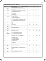
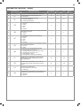
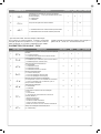
Safety warnings
2.1
2.2
2.3
2.4
4.1
4.2
4.3
4.4
4.5
5.1
5.2
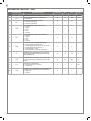
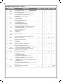
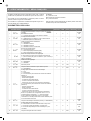
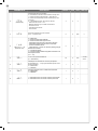
Introducing the product
Description of the control unit
Description of the connections
Models and technical characteristics
List of cables required
Preliminary Checks
Installing the Product
Electric connections
Display during normal operation
Autolearning of the travel stroke
Transmitter learning procedure
Customising the system - BASIC MENU
Testing and commissioning
Testing
Commissioning
Further details - ADVANCED MENU
Instructions and warnings for the
nal user
EC declaration of conformity
pag. 3
pag. 4
pag. 4
pag. 4
pag. 4
pag. 5
pag. 5
pag. 6
pag. 6
pag. 7
pag. 9
pag. 9
pag. 10
pag. 14
pag. 14
pag. 14
pag. 15
pag. 20
pag. 135
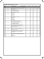
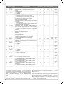
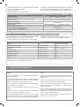
TABLE OF CONTENTS

3
EN
1 - SAFETY WARNINGS
ORIGINAL INSTRUCTIONS - important safety instructions. Fol-
low the instructions since incorrect installation can lead to se-
vere inquiry! Save these instructions.
Read the instructions carefully before proceeding with installation.
The design and manufacture of the devices making up the
product and the information in this manual are compliant with
current safety standards. However, incorrect installation or
programming may cause serious injury to those working on or
using the system. Compliance with the instructions provided
here when installing the product is therefore extremely impor-
tant.
If in any doubt regarding installation, do not proceed and contact the
Marantec Technical Service for clarications.
Under European legislation, an automatic door or gate system
must comply with the standards envisaged in the Directive
2006/42/EC (Machinery Directive) and in particular standards
EN 12453; EN 12635 and EN 13241-1, which enable declaration
of presumed conformity of the automation system.
Therefore, nal connection of the automation system to the electri-
cal mains, system testing, commissioning and routine maintenance
must be performed by skilled, qualied personnel, in observance of
the instructions in the “Testing and commissioning the automation
system” section.
The aforesaid personnel are also responsible for the tests required
to verify the solutions adopted according to the risks present, and for
ensuring observance of all legal provisions, standards and regula-
tions, with particular reference to all requirements of the EN 12453
standard which establishes the test methods for testing door and
gate automation systems.
Before starting installation, perform the following checks and
assessments:
ensure that every device used to set up the automation system is
suited to the intended system overall. For this purpose, pay special
attention to the data provided in the “Technical specications” sec-
tion. Do not proceed with installation if any one of these devices is
not suitable for its intended purpose;
check that the devices purchased are sucient to guarantee system
safety and functionality;
perform a risk assessment, including a list of the essential safety
requirements as envisaged in Annex I of the Machinery Directive,
specifying the solutions adopted. The risk assessment is one of the
documents included in the automation system’s technical le. This
must be compiled by a professional installer.
Considering the risk situations that may arise during instal-
lation phases and use of the product, the automation system
must be installed in compliance with the following safety pre-
cautions:
never make modications to any part of the automation system other
than those specied in this manual. Operations of this type can only
lead to malfunctions. The manufacturer declines all liability for da-
mage caused by unauthorised modications to products;
if the power cable is damaged, it must be replaced by the manufac-
turer or its after-sales service, or in all cases by a person with similar
qualications, to prevent all risks;
do not allow parts of the automation system to be immersed in water
or other liquids. During installation ensure that no liquids are able to
enter the various devices;
should this occur, disconnect the power supply immediately and
contact a Marantec Service Centre. Use of the automation system in
these conditions may cause hazards;
never place automation system components near to sources of heat
or expose them to naked lights. This may damage system compo-
nents and cause malfunctions, re or hazards;
The drive shall be disconnected from its power source during
cleaning, maintenance and when replacing parts. If the discon-
nect device is not in a visible location, ax a notice stating:
“MAINTENANCE IN PROGRESS”:
connect all devices to an electric power line equipped with an
earthing system;
the product cannot be considered to provide eective protection
against intrusion. If eective protection is required, the automation
system must be combined with other devices;
the product may not be used until the automation system “commis-
sioning” procedure has been performed as specied in the “Automa-
tion system testing and commissioning” section;
the system power supply line must include a circuit breaker device
with a contact gap allowing complete disconnection in the conditions
specied by class III overvoltage;
use unions with IP55 or higher protection when connecting hoses,
pipes or cable glands;
the electrical system upstream of the automation system must com-
ply with the relevant regulations and be constructed to good wor-
kmanship standards;
this appliance can be used by children aged from 8 years and above
and persons with reduced physical, sensory or mental capabilities or
lack of experience and knowledge if they have been given supervi-
sion or instruction concerning use of the appliance in a safe way and
understand the hazards involved;
before starting the automation system, ensure that there is no-one
in the immediate vicinity;
before proceeding with any cleaning or maintenance work on the
automation system, disconnect it from the electrical mains;
special care must be taken to avoid crushing between the part ope-
rated by the automation system and any xed parts around it;
children must be supervised to ensure that they do not play with the
equipment.
that the drive cannot be used with a driven part incorporating a wi-
cket door unless the drive can only be operated with the wicket door
in the safe position;
The automation system component packaging material must
be disposed of in full observance of current local waste dispo-
sal legislation.
Marantec reserves the right to amend these instructions if neces-
sary; they and/or any more recent versions are available at www.
marantec.com
Frequently examine the installation for imbalance where ap-
plicable and signs of wear or damage to cables, springs and
mounting.
Do not use if repair or adjustment is necessary.
ATTENTION !
ATTENTION !
ATTENTION !
ATTENTION !
ATTENTION !

4
EN
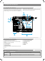
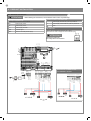
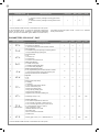
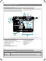
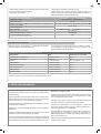
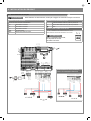
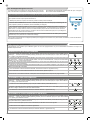
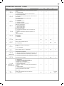
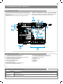
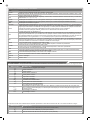
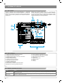
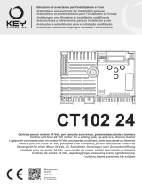
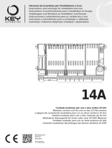
2.1 - Description of the control unit
The CBX10224 control unit is the most modern, ecient system for
the control of Marantec motors for the electric opening and closure
of sliding gates, up-and-over doors and electromechanical barrier.
All other, improper, use of the control unit is forbidden. The
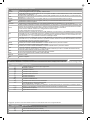
2.2 - Description of the connections
1- Motor power supply connections and encoder
2- Transformer power supply connections
3- 24Vdc and 24Vac output connections to controls and safety
devices
4- Connector for battery charger KBP
5- Limit switch connector
6- Functions display
7- Safety device dip switch
8- Fuse 2A slow-acting
9- STOP-PH2-PH1-OPEN-CLOSE-PAR-SBS safety led and led
input led
10- Limit switch indicator LED LSC
11- Limit switch indicator LED LSO
12- STEPPING SBS button
13- UP + button
14- MENU button
15- DOWN - button
16- Antenna
17- KEY led
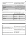
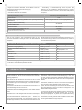
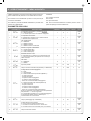
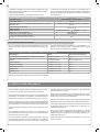
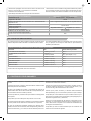
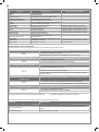
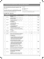
2.3 - Models and technical characteristics
CBX10224 has a display allowing easy programming and constant
monitoring of the input status; the menu structure also allows easy
setting of working times and operating modes.
2 - INTRODUCING THE PRODUCT
CODE DESCRIPTION
CBX10224 24V control unit for sliding gates, up-and-over doors or electromechanical barrier
CBX10224F 24V control unit FAST LINE for sliding gates, up-and-over doors or electromechanical barrier
NEG
PH-POW
STOP
STOP
STOP
STOP
PH2
PH1
OPEN
CLOSE
PAR
SBS
PH2
PH1
PH 2
COM
FLASH
IND
LED
SHIELD
UP
MENU
SBS
DOWN
(RADIO)
ANT
24 VAC
24 VAC
PH 1
OPEN
CLOSE
SBS
PAR
COM
POWER SUPPLY
NEG
ENC
V +
M -
M +
BATTERY
LS 1
LS 2
KEY
COM
1
4
16
8
2
5
7
9
6
17
3
10
11
13
12
15
14

5
EN
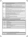
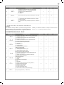
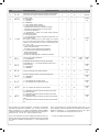
3 - PRELIMINARY CHECKS
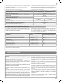
2.4 - List of cables required
The cables required for connection of the various devices in a stan-
dard system are listed in the cables list table.
Before installing the product, perform the following checks and in-
spections:
check that the gate, the door or the barrier is suitable for automation;
the weight and size of the gate or door and the balance of the barrier
boom must be within the operating limits specied for the automa-
tion system in which the product is installed;
heck that the gate or door has rm, eective mechanical safety
stops;
make sure that the product xing zone is not subject to ooding;
high acidity or salinity or nearby heat sources might cause the pro-
duct to malfunction;
in case of extreme weather conditions (e.g. snow, ice, wide tempera-
ture variations or high temperatures), friction may increase, causing
a corresponding rise in the force needed to operate the system;
the starting torque may therefore exceed that required in normal
conditions;
check that when operated by hand the gate, the door or the barrier
moves smoothly without any areas of greater friction or derailment
risk;
check that the gate, door or the barrier is well balanced and will the-
refore remain stationery when released in any position;
check that the electricity supply line to which the product is to be
connected is suitably earthed and protected by an overload and dif-
ferential safety breaker device;
he system power supply line must include a circuit breaker device
with a contact gap allowing complete disconnection in the conditions
specied by class III overvoltage;
ensure that all the material used for installation complies with the
relevant regulatory standards.
The cables used must be suitable for the type of installation; for
example, an H03VV-F type cable is recommended for indoor appli-
cations, while H07RN-F is suitable for outdoor applications.
- Power supply with protection against short-circuits inside the con-
trol unit, on motors and on the connected accessories.
- Obstacle detection.
- Automatic learning of working times.
- Safety device deactivation by means of dip switches: there is no
need to bridge the terminals of safety devices which are not instal-
led - the function is simply disabled by means of a dip switch.
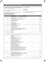
* If the power supply cable is more than 20 m long, it must be of larger gauge (3x2.5mm2) and a safety grounding system must be installed
near the automation unit.
TECHNICAL SPECIFICATIONS: CBX10224 CBX10224F
Power supply (L-N) 230 Vac (+10% - 15%) 50-60 Hz
Max motor load 150 W
Output for Vac accessories power/device test power Vdc
24 Vac without regulation 200 mA / 24 Vdc without regu-
lation 250 mA
Courtesy light output
24 Vdc 25 W
Flashing light output
Pause time Adjustable 0 - 900 sec. Adjustable 0,1 - 90 sec.
Operating temperature -20 °C + 55 °C
230 Vac power supply line fuses 1.6 A slow-acting
Max. number of transmitters storage
Compatible with all Marantec “Bi-Linked” transmitters
200
ELECTRIC CABLE TECHNICAL SPECIFICATIONS:
Connection cable maximum allowable limit
Control unit power supply line 1 x cable 3 x 1,5 mm
2
20 m *
Flashing light, courtesy light
Antenna
3 x 0,5 mm
2
**
1 x cable type RG58
20 m
20 m (advised < 5 m)
Electric lock 1 x cable 2 x 1 mm
2
10 m
Transmitter photocells 1 x cable 2 x 0,5 mm
2
20 m
Receiver photocells 1 x cable 4 x 0,5 mm
2
20 m
Sensitive edge 1 x cable 2 x 0,5 mm
2
20 m
Key-switch 1 x cable 4 x 0,5 mm
2
** 20 m

6
EN
4 - PRODUCT INSTALLATION
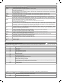
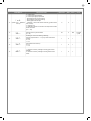
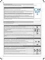
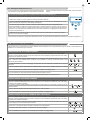
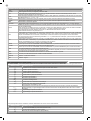
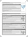
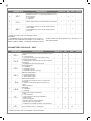
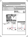
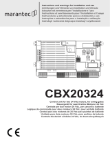
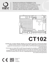
4.1 - Electrical connections
Before making the connections, ensure that the control unit is not powered up
ON
1 2 3
STOP
PH2
PH1
MOTOR CONNECTOR
Power supply connection terminal board
M + Power supply motor
M - Power supply motor
V + Power supply encoder
ENC Encoder signal
NEG Maximum encoder power supply
POWER SUPPLY CONNECTOR
L Power supply live 230 Vac (120 Vac) 50-60 Hz
N Power supply neutral 230 Vac (120 Vac) 50-60 Hz
Earth
DIP SWITCH
Set on “ON” to disable inputs STOP, PH1, PH2
Eliminates the need to bridge the terminal board inputs.
with the dip switch ON,
the safety devices are disabled
ATTENTION !
ATTENTION !
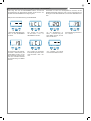
ELECTRICAL CONNECTIONS
FOR ENERGY SAVING
NEG
PH-POW
STOP
STOP
PH 2
COM
FLASH
IND
LED
24 VAC
24 VAC
PH 1
OPEN
CLOSE
SBS
PAR
COM
PHOTOTEST
OUTPUT LED
OPEN
PHOTOCELL 1
PHOTOCELL 2
CLOSE
PARCIAL
STEP BY STEP
COMMON
STOP/EDGE
INDICATOR
NEGATIVE
24 VAC
24 VAC
2
3
4
1
1
2
TX
RX
NC
PH2
2
3
4
1
1
2
TX
RX
PH1
GND
_
12/24
AC/DC
GND
_
12/24
AC/DC
COM
OUT
GND
_
12/24
AC/DC
GND
_
12/24
AC/DC
COM
OUT
NC
POWER
POWER SUPPLY
SUPPLY
N
T1,6A
L
230Vac
50/60Hz
COM
LED
FLASH
STOP
STOP
PH2
PH1
OPEN
CLOSE
PAR
SBS
PH2
PH1
SHIELD
UP
MENU
SBS
DOWN
(RADIO)
ANT
NEG
ENC
V +
M -
M +
BATTERY
LS 1
LS 2
KEY
COM
NEG
PH-POW
STOP
STOP
PH 2
COM
FLASH
IND
LED
24 VAC
24 VAC
PH 1
OPEN
CLOSE
SBS
PAR
COM
PHOTOTEST
OUTPUT LED
OPEN
PHOTOCELL 1
PHOTOCELL 2
CLOSE
PARCIAL
STEP BY STEP
COMMON
STOP/EDGE
INDICATOR
NEGATIVE
24 VAC
24 VAC
2
3
4
1
1
2
TX
RX
NC
PH2
2
3
4
1
1
2
TX
RX
PH1
GND
_
12/24
AC/DC
GND
_
12/24
AC/DC
COM
OUT
GND
_
12/24
AC/DC
GND
_
12/24
AC/DC
COM
OUT
NC
POWER
POWER SUPPLY
SUPPLY
N
T1,6A
L
230Vac
50/60Hz
STOP
STOP
PH2
PH1
OPEN
CLOSE
PAR
SBS
PH2
PH1
SHIELD
UP
MENU
SBS
DOWN
(RADIO)
ANT
NEG
ENC
V +
M -
M +
BATTERY
LS 1
LS 2
KEY
COM

7
EN
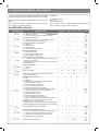
SAFETY AND CONTROL DEVICE CONNECTOR
COM Common for the FLASH-IND-LED inputs
FLASH Flashing light output 24Vdc (without regulation), maximum 25W
IND
IND output for gate open indicator light 24 Vdc not regulated 4W MAX / Electric lock output 12Vac, 15VA maximum
selectable with parameter IN.D.
LED
Courtesy light output 24Vdc (without regulation), maximum 25W, controllable also via radio ON-OFF command (radio
channel 4 selecting fC.y. = 2, tC.y. = 0)
24 VAC Accessories power supply 24 Vac without regulation, 200 mA (with battery operation output not active)
24 VAC Accessories power supply 24 Vac without regulation, 200 mA (with battery operation output not active)
NEG Accessories power supply negative
PH-POW
Photocells PH1 and PH2 power supply positive; phototest can be selected with parameter tp.h. 24 Vdc, 250 mA
STOP
STOP safety device, NC contact between STOP and STOP (warning, with dip switch 1 ON the safety device input is
o). This input is classied as a safety device; the contact can be deactivated at any time, cutting out the automation
system and disabling all functions, including Automatic Closure.
Safety sensor edge, ON/OFF, NC contact or resistive 8K2 between STOP and STOP.
Input selectable with parameter Ed.m.
PH2
Photocells (opening), NC contact between PH2 and COM (warning, with dip switch 2 ON the PHOTOCELL 2 safety
device input is o). The photocell is tripped at any time during opening of the automation system, halting operation
immediately; the automation system will continue opening when the contact is restored. In the event of intervention on
closure (parameter Ph.2. = 0) the device stops and on release re-opens.
PH1
Photocells (closing), NC contact between PH1 and COM (warning, with dip switch 3 ON the PHOTOCELL 1 safety
device input is o) The photocell is tripped at any time during closing of the automation system, halting operation im-
mediately and reversing the travel direction.
OPEN
OPEN command NO contact between OPEN and COM
Contact for the HOLD-TO-RUN function. The gate OPENS as long as the contact is held down
CLOSE
CLOSE command NO contact between CLOSE and COM
Contact for the HOLD-TO-RUN function. The gate CLOSES as long as the contact is held down
PAR
PARCIAL command NO contact between PAR and COM
Used to open the gate partially, depending on the software setting (not active in barrier/up-and-over mode)
SBS
STEPPING command NO contact between SBS and COM
Open/Stop/Close/Stop command, or as set in the software
COM Common for the PH2-PH1-OPEN-CLOSE-PAR-SBS inputs
SHIELD Antenna - shield -
ANT Antenna - signal -
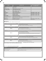
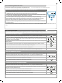
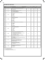
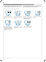
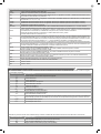
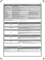
4.2 - Display during normal operation
In “NORMAL OPERATING MODE”, i.e. when the system is powered up normally, the 3-gure LCD display shows the following status messages:
MESSAGES MEANING
--
Gate closed or switch-on after shutdown
OP
Gate opening
CL
Gate closing
SO
Gate stopped during opening
SC
Gate stopped during closure
F1
Photocell 1 tripped
F2
Photocell 2 tripped
ALI
Re-alignment procedure
oP
Gate stopped without automatic reclosure
-tC
Gate open with timed reclosure
Flashing dash counting in progress
L--
Learning started on limit switch (move the gate o the limit switch to continue the learning procedure) or lear-
ning stopped due to trip of safety device or motor inversion.
LOP
Learning opening
LCL
Learning closure
MESSAGES MEANING
-.-
Limit switch CLOSED (one dot between the two lines)
tC.
Limit switch OPEN (a point to the right)
SO
No limit switch active (no dots present)
In addition, the dots between the gures illustrate the status of the limit switches, as described in greater detail below:
n

8
EN
Malfunctions
This section lists a number of malfunctions which may occur.
SURGE OVERLOAD ALARM The motor’s current drawdown has increased very quickly
EOL
1. The gate has struck an obstacle.
2. Friction on runners or rack (see motor current [A]).
SAFETY EDGE ALARM The control unit has received a signal from the safety edge
EED
1. The safety edge has been pressed.
2. The safety edge is not connected correctly.
LIMIT SWITCH ALARM The limit switches are not working properly
ELS
1. The limit switches are damaged.
2. The limit switches are not connected.
3. Check the travel time which has passed without tripping of the limit switches.
After eliminating the cause of the alarm, to delete all errors simply
press the “DOWN -” key or press the SBS (STEPPING) command
The display returns to the normal screen.
PHOTOCELL ALARM/SAFETY EDGE Phototest fail outcome.
EPH
1. Check the photocell and the safety edge connections.
2. Check that the photocells and the safety edg are operating correctly.
ENCODER ALARM Encoder encoder (only if encoder is present)
EEN
1. Check the encoder connections.
2. Check that the encoder are operating correctly.
EVENT DESCRIPTION
KEY TO MAIN CONTROL
FLASHING LIGHT AND KEY LEDS
CONTROL UNIT
opening Gate opening
closure Gate closing
automatic closure Gate open with timed reclosure active
stop during closure Gate stopped during closure
stop during opening Gate stopped during opening
open Gate completely open without automatic reclosure
closed Gate completely closed
programmation During the programming phase 2 quick ashes + pause + 1 ash
obstacle M1 Motor 1 obstacle detected 4 quick ashes + pause, 3 times
photo 1! Photocell 1 tripped 2 quick ashes + pause, 3 times
photo 2! Photocell 2 tripped 2 quick ashes + pause, 3 times
sensitive edge! Sensitive edge tripped 5 quick ashes + pause, 3 times
parcial opening Parcial opening in progress
automatic parcial closure Gate opening to parcial position with timed reclosure activated
realignment Realignment after a manual release
phototest error Phototest error detected 3 quick ashes + pause, 3 times
encoder error Encoder error detected 7 quick ashes
DISPLAY MEANING
Status display (--, OP, CL, SO, ecc..) Description of the control unit (--, OP, CL, SO, ecc..)
Maneuvers performed Counter displays alternating the thousands (without dots) and the units (with dots).
Motor current [A] Current absorbed by the motor
Press “UP“ to read the following parameters on display.

9
EN
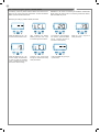
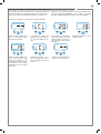
4.4 - Learning a transmitter
A transmitter can be “learned” via the specic programming menu or by remote memorisation, using a previously memorised transmitter.
UP
SBS
DOWN
MENU
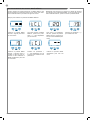
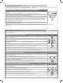
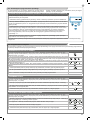
4.3 - Autolearning of the travel stroke
The rst time the control unit is powered up, an autolearning proce-
dure must be carried out to acquire fundamental parameters such
as the travel stroke length and deceleration points.
AUTOLEARNING OF THE TRAVEL STROKE AND MAIN PARAMETERS
The decelerations will be those set in the menu, with the same percentage during both opening and closing.
1. Release the gate or door, move it onto the central position and lock it in place again.
2. Hold down the + and MENU buttons SIMULTANEOUSLY for more than 5 seconds, until the screen shows
LOP and get ready to press the DOWN key (see illustration) if necessary.
3. If the rst operation is NOT opening of the gate, press the DOWN key to stop the autolearning.
Then press SBS to restart the acquisition: the gate starts moving again, in the right direction. The motor
opens the gate at low speed to the opening limit switch. On reaching the opening limit switch, the gate re-
starts in the closing direction at low speed until it reaches the closing limit switch, displaying LCL.
4. Perform a number of opening, closing and sudden stop commands to ensure that the system is solid with
no assembly defects.
All the main parameters are set with the default settings by the control unit. To customise the installation, proceed as described in point 4.5
below.
CLEARING THE ENTIRE RECEIVER MEMORY
If you are in programming mode exit pressing the MENU button until -- appears. Press the DOWN (RADIO)
button for more than 2 seconds. Until the display shows the word “rd” (radio), then release the button
1. Press the DOWN (RADIO) button and hold it down until the LED lights up (about 3 seconds) and then goes
out (about 3 seconds). Release the key.
(>3s)-> (>3s)->
2. About 1 second after the key is released, the KEY LED starts to ash
(1s)+ (1s)+
3. Press the key on the receiver as the LED ashes for the third time
4. If the deletion has been successful, the KEY LED will give one long ash
3s
MEMORISING A REMOTE CONTROL
If you are in programming mode exit pressing the MENU button until -- appears. Press the DOWN (RADIO)
button for more than 2 seconds. Until the display shows the word “rd” (radio), then release the button
1. Press and release the DOWN (RADIO) button a number of times equal to the number of the function to be
selected: once for function STEP BY STEP, twice for function PARTIAL, three times for function ONLY OPEN,
four times for function LIGHT ON/OFF
+ +
2. The KEY LED will ash a number of times equal to the number of the function selected, with 1 second pauses
between ashes
+1s +1s
3. Press the back key of the remote control to be memorized and then press the front key within 7 seconds
2s
4. If the memorization has been successful, the KEY LED will give one long ash
3s
5. To memorize another remote control on the same function, repeat point 3
N.B If no commands are given for 7 seconds, the receiver automatically quits the programming mode
DELETING A REMOTE CONTROL
If you are in programming mode exit pressing the MENU button until -- appears. Press the DOWN (RADIO)
button for more than 2 seconds. Until the display shows the word “rd” (radio), then release the button
1. Press the DOWN (RADIO) button until the LED lights up (about 3 seconds), then release the button
(>3s)->
2. Press the key of the remote control to be deleted within 7 seconds
3. If the deletion has been successful, KEY LED will give one long ash
3s

10
EN
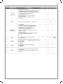
4.5 - Customising the system - BASIC MENU
If necessary, users may select a BASIC MENU which allows modi-
cation of the control unit’s basic parameters. To select the BASIC
MENU proceed as described below.
WARNING: to be certain of accessing the NORMAL OPERATION
display state, the starting point for accessing the BASIC MENU,
press the MENU key twice
Exampling of modifying a BASIC MENU parameter
UP
UP
UP
UP
UP UP
UP
DOWN
DOWN
DOWN
DOWN
DOWN DOWN
DOWN
MENU
MENU
MENU
MENU
MENU MENU
MENU
After accessing the BASIC
MENU, press the + and – keys
to scroll through the functions.
Press the MENU key quickly to
quit the menu.
Press the MENU key for 1 se-
cond to access the basic menu.
Press the + and – keys to scroll
through the functions to modify
other parameters.
Press the + and – keys to to
modify the value.
Press the MENU key for 1 se-
cond to display the parameter
in order to save the modied
value, or MENU quickly to quit
the function without saving.
To access the value modica-
tion function, press the MENU
key for 1 second, until the va-
lue starts to ash quickly.

11
EN
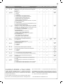
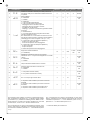
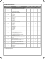
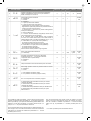
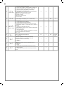
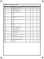
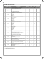
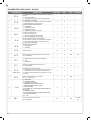
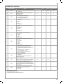
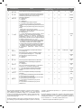
PARAMETERS DESCRIPTION DEFAULT MIN MAX UNIT
1
TCL
Automatic reclosure time (0 = o) 0 0 900 s
2
ttr
Reclosing time after transit on PH1
(0 = o)
0 0 30 s
3
SEI
Sensitivity on obstacles
0 = Maximum impact force
10 = Minimum impact force
3 0 10
4
SFO
Motor speed during opening
1 = minimum
2 = low
3 = medium
4 = high
5 = maximum
4 1 5
5
SSO
Motor speed during opening deceleration phase
1 = minimum
2 = low
3 = medium
4 = high
5 = maximum
1 1 5
6
SFC
Motor speed during closing
1 = minimum
2 = low
3 = medium
4 = high
5 = maximum
4 1 5
7
SSC
Motor speed during closing deceleration phase
1 = minimum
2 = low
3 = medium
4 = high
5 = maximum
1 1 5
8
SBS
STEP BY STEP or SBS conguration:
0 = Normal (AP-ST-CH-ST-AP-ST…)
1 = Alternate STOP (AP-ST-CH-AP-ST-CH…)
2 = Alternate (AP-CH-AP-CH…)
3 = Apartment block – timer
4 = Apartment block with immediate reclosure
0 *** 0 4
9
sT2
Additional stop input:
0 = disabled
1 = The PAR input becomes the STOP function. NO
contact input
0 0 1
10
LSI
Deceleration distance
0 to 100 = Motor deceleration percentage during
opening and closure
20 0 ** 100 %
11
BlT
Post blackout procedure
0 = No action, remains stationery
1 = Closure
0 0 1 s
12
SBY
Energy saving: enables photocell switch-o when gate
is closed
0= disabled
1= enabled
0 0 1
*** = The default value for barriers is 4
PARAMETERS CBX10224

EN
12
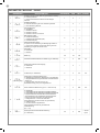
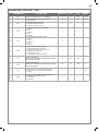
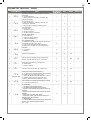
PARAMETERS CBX10224F - SU500F
PARAMETERS DESCRIPTION DEFAULT MIN MAX UNIT
1
TCL
Automatic reclosure time (0 = o) 0 0 900 s
2
ttr
Reclosing time after transit on PH1
(0 = o)
0 0 30 s
3
SEI
Sensitivity on obstacles
0 = Maximum impact force
10 = Minimum impact force
3 0 10
4
SFO
Motor speed during opening
1 = minimum
2 = low
3 = medium
4 = high
5 = maximum
5 1 5
5
SSO
Motor speed during opening deceleration phase
1 = minimum
2 = low
1 1 2
6
SFC
Motor speed during closing
1 = minimum
2 = low
3 = medium
4 = high
5 = maximum
5 1 5
7
SSC
Motor speed during closing deceleration phase
1 = minimum
2 = low
1 1 2
8
SBS
STEP BY STEP or SBS conguration:
0 = Normal (AP-ST-CH-ST-AP-ST…)
1 = Alternate STOP (AP-ST-CH-AP-ST-CH…)
2 = Alternate (AP-CH-AP-CH…)
3 = Apartment block – timer
4 = Apartment block with immediate reclosure
0 0 4
9
LSI
Deceleration distance in opening
from 5 to 100 = Motor deceleration percentage during
opening
20 5 100 %
10
LS2
Deceleration distance in closing
from 5 to 100 = Motor deceleration percentage during
closure
20 5 100 %
11
BlT
Post blackout procedure
0 = No action, remains stationery
1 = Closure
0 0 1
12
SBY
Energy saving: enables photocell switch-o when
barrier is closed
0= disabled
1= enabled
0 0 1

13
EN
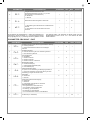
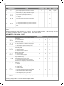
PARAMETERS CBX10224F - PA3F
PARAMETERS DESCRIPTION DEFAULT MIN MAX UNIT
1
TCL
Automatic reclosure time (0 = o) 0 0 600 0,1 sec
2
ttr
Reclosing time after transit on PH1
(0 = o)
0 0 300 0,1 sec
3
SEI
Sensitivity on obstacles
0 = Maximum impact force
5 = Minimum impact force
0 0 5
4
SFO
Motor speed during opening
1 = minimum
2 = low
3 = medium
4 = high
5 = maximum
5 1 5
5
SFC
Motor speed during closing
1 = minimum
2 = low
3 = medium
4 = high
5 = maximum
5 1 5
6
SBS
STEP BY STEP or SBS conguration:
0 = Normal (AP-ST-CH-ST-AP-ST…)
1 = Alternate STOP (AP-ST-CH-AP-ST-CH…)
2 = Alternate (AP-CH-AP-CH…)
3 = Apartment block – timer
4 = Apartment block with immediate reclosure
4 0 4
7
LSI
Deceleration distance in opening
from 40 to 100 = Motor deceleration percentage
during opening
55 40 100 %
8
LS2
Deceleration distance in closing
from 40 to 100 = Motor deceleration percentage
during closure
68 40 100 %
9
BlT
Post blackout procedure
0 = No action, remains stationery
1 = Closure
0 0 1 sec
10
SBY
Energy saving: enables photocell switch-o when
barrier is closed
0= disabled
1= enabled
0 0 1

14
EN
5.2 Commissioning
Once all (and not just some) of the system devices have passed the
testing procedure, the system can be commissioned;
the system’s technical dossier must be produced and kept for 10
years. It must contain the electrical wiring diagram, a drawing or
photograph of the system, the analysis of the risks and the solutions
adopted to deal with them, the manufacturer’s declaration of con-
formity for all connected devices, the operator’s manual for every
device and the system maintenance plan;
x a dataplate with the details of the automation, the name of the
person who commissioned it, the serial number and year of con-
struction and the CE marking on the gate or door;
also t a sign specifying the procedure for releasing the system by
hand;
draw up the declaration of conformity, the instructions and precau-
tions for use for the end user and the system maintenance plan and
consign them to the end user;
ensure that the user has fully understood how to operate the system
in automatic, manual and emergency modes;
the end user must also be informed in writing about any risks and
hazards still present;
After detecting an obstacle, the gate or door stops during its
opening travel and automatic closure is disabled; to restart
operation, the user must press the control button or use the
transmitter.
5 - TESTING AND COMMISSIONING THE AUTOMATION SYSTEM
5.1 Testing
All system components must be tested following the procedures de-
scribed in their respective operator’s manuals;
ensure that the recommendations in Chapter 1 - Safety Warnings -
have been complied with;
check that the gate or door is able to move freely once the automa-
tion system has been released and is well balanced, meaning that it
will remain stationery when released in any position;
check that all connected devices (photocells, sensitive edges, emer-
gency buttons, etc.) are operating correctly by performing gate or
door opening, closing and stop tests using the connected control
devices (transmitters, buttons or switches);
perform the impact measurements as required by the EN12445
standard, adjusting the control unit’s speed, motor force and decele-
ration functions if the measurements do not give the required results,
until the correct setting is obtained.
The system must be tested by a qualied technician, who must per-
form the tests required by the relevant standards in relation to the
risks present, to check that the installation complies with the relevant
regulatory requirements, especially the EN12445 standard which
species the test methods for gate and door automation systems.
ATTENTION !

15
EN
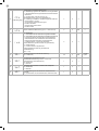
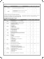
6 - FURTHER DETAILS - ADVANCED MENU
The ADVANCED MENU allows the system to be further customised
by modifying parameters not accessible from the basic menu.
To access the ADVANCED menu, press the MENU key and hold it
down for 5 seconds.
To modify ADVANCED MENU parameters, proceed as described
for the BASIC MENU.
LEGENDA:
SL= sliding gate
BA= barrier
OH= up-and-over door
N.B. Some default functions/display items may vary with respect to
the type of motor selected.
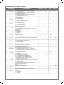
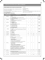
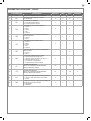
PARAMETERS
DESCRIPTION DEFAULT MIN MAX UNIT TYPE
1
SP.h.
Use of PHOTO1 when starting from closed
0 = PHOTO1 is checked
1 = The gate starts even with PHOTO1 excited
1 0 1
SL/BA/
OH
2
Ph.2.
Use of PHOTO2
0 = Enabled during both opening and closing AP/CH
1 =Only enabled during opening AP
1 0 1
SL/BA/
OH
3
tP.h.
Photo-device test
0 = o
1 = PHOTO1 on
2 = PHOTO2 on
3 = PHOTO1 and PHOTO2 on
0 0 3
SL/BA/
OH
4
Ed.m.
STOP input selection
0 = STOP contact (NC)
1 = Resistive safety edge (8k2)
2 = Contact safety edge (NC)
0 0 2
SL/BA/
OH
5
iE.D.
Sensitive edge tripping mode
0= only tripped during closure with direction reversal
1 = stops the automation (during both opening and
closure) and retreats from the obstacle
0 0 1
SL/BA/
OH
6
tE.D.
Edge test
0 = o
1 = on
0 0 1
SL/BA/
OH
7
LP.o.
Parcial opening 50 10 100 % SL
8
TP.C.
Time for automatic closure from parcial opening (0=o) 0 0 900 s SL
9
FP.r.
Flashing light output setup
0 = Steady
1 = Flashing
2 = Two-colour LED strip for barrier (MODE 1)
- gate closed steady red
- gate open LEDs o
- during opening ashing green
- during closing ashing red
- stopped not on limit switch ashing red
3 = two-colour LED strip for barrier (MODE 2)
- gate closed steady red
- gate open steady green
- during opening ashing green
- during closing ashing red
- stopped not on limit switch ashing red
N.B.: if this parameter is set as 2 or 3, the settings of
parameter .D. will be ignored.
If this parameter is set as 2 or 3, the ashing light and gate
open light outputs will be used for operation with the LED strip
1 * 0 3
SL/BA/
OH
10
tP.r.
Pre-ashing time (0 = o) 0 0 20 s
SL/BA/
OH
11
FC.Y.
Courtesy light setup
0 = On at end of operation for time TCY
1 = On if gate not closed + duration of TCY
2 = On if courtesy light timer (TCY) time not out
0 0 2
SL/BA/
OH
12
tC.Y.
Courtesy light on time 0 0 900 s
SL/BA/
OH
n
PARAMETERS CBX10224

EN
16
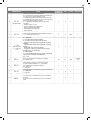
PARAMETERS
DESCRIPTION DEFAULT MIN MAX UNIT TYPE
13
CL.E.
Clearance. Allows to stop before the fully open position: it
is useful to avoid mechanical stress during opening.
0 0 30 % BA/OH
14
de.a.
Hold-to-run
0 = o
1 = on
0 0 1
SL/BA/
OH
15
IN.D.
0 = deactivated
1 = gate open light ON/OFF
2 = gate open light proportional
- Slow ashing with gate opening
- Quick ashing with gate closing
- Steady light if gate open
- 2 ashes + pause with gate stationary (position other than
closed)
3 = Electric lock
4 = Magnetic electric lock function with output active when
gate/door is closed
N.B. interface with an external relay with 24 Vdc winding. To
activate this function, the pre-ash must be enabled at the
recommended value of 1 sec (tP.r. ≠ 0)
5 = LED strip for gate open light (MODE 1)
- steady light when open and closed
- ashing light in all other positions
6 = LED strip for gate open light (MODE 2)
- gate closed steady red
- gate open LEDs o
ashing red in all other positions
0 0 6
SL/BA/
OH
16
se.r.
Service interval cycle threshold.
(0 = o)
10 0 200
x 1000
cycles
SL/BA/
OH
17
se.f.
Enabling of continuous ashing indicating
service required with se.r. ≠ 0 (only active with gate
closed).
0 = o
1 = on
0 0 1
SL/BA/
OH
18
EL.T.
Electric lock activation time in seconds 4 1 10 s
SL/BA/
OH
19
ST.P.
High-speed motor start-up.
0 = on
1 = o
0 0 1
SL/BA/
OH
20
EN.C.
1 = O (use of virtual encoder)
2 = On (use of motor’s physical encoder)
1 1 2
SL/BA/
OH
21
NE.P.
1 to 10 pulses per revolution of the physical encoder 4 1 10
SL/BA/
OH
22
DE.F.
2 = Restore of factory settings for sliding gate motor
SU700M
3 = Restore of factory settings for sliding gate motor
SU1100M
4 = Factory setting restore for 4/6 mt barrier
5 = Factory setting restore for 8 mt barrier
0 0 5
SL/BA/
OH
To set the default values: 1) access the advanced programming
function; 2) select the “dEf” parameter”; 3) activate the modication
mode (“0” on display”); 4) accept the modication (press “MENU”
and hold it down). A countdown should now appear: 49,48...,1 down
to “don“. Release the key when nished.
To use both colours of a two-colour LED strip, make the connections
as explained in the CTLIGHT instructions and modify parameters
FP.r. as required (setting 2 or 3).
To use just one colour of a LED strip, make the connections as ex-
plained in the CTLIGHT instructions and modify parameter IN.D. as
required (setting 5 or 6); parameter FP.r. cannot be set on 2 or 3.
* = The default value for barriers is 3

17
EN
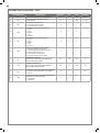
PARAMETERS CBX10224F - SU500F
PARAMETERS DESCRIPTION DEFAULT MIN MAX UNIT
1
SP.h.
Use of PHOTO1 when starting from closed
0 = PHOTO1 is checked
1 = The barrier starts even with PHOTO1 excited
1 0 1
2
Ph.2.
Use of PHOTO2
0 = Enabled during both opening and closing AP/CH
1 =Only enabled during opening AP
1 0 1
3
tP.h.
Photo-device test
0 = o
1 = PHOTO1 on
2 = PHOTO2 on
3 = PHOTO1 and PHOTO2 on
0 0 3
4
Ed.m.
STOP input selection
0 = STOP contact (NC)
1 = Resistive safety edge (8k2)
2 = Contact safety edge (NC)
0 0 2
5
iE.D.
Sensitive edge tripping mode
0= only tripped during closure with direction reversal
1 = stops the automation (during both opening and
closure) and retreats from the obstacle
0 0 1
6
tE.D.
Edge test
0 = o
1 = on
0 0 1
7
LP.o.
Parcial opening 50 30 100
8
TP.C.
Time for automatic closure from parcial opening (0=o) 0 0 900 sec
9
FP.r.
Flashing light output setup
0 = Steady
1 = Flashing
1 0 1
10
tP.r.
Pre-ashing time (0 = o) 0 0 20 sec
11
FC.Y.
(LED output)
Courtesy light setup
0 = On at end of operation for time TCY
1 = On if not closed + duration of TCY
2 = On if courtesy light timer (TCY) time not out
0 0 2
12
tC.Y.
Courtesy light on time, if FC.Y. dierent from 3
0 0 900 sec
13
IN.D.
0 = deactivated
1 = open light ON/OFF
2 = open light proportional
- Slow ashing with opening
- Quick ashing with closing
- Steady light if open
- 2 ashes + pause with barrier stationary (position other
than closed)
3 = Electric lock
4 = Magnetic electric lock function with output active when
gate is closed (tP.r.>0)
0 0 4
14
se.r.
Service interval cycle threshold.
(0 = o)
50 0 200
x 10.000
cycles
15
se.f.
Enabling of continuous ashing indicating
service required with se.r. ≠ 0 (only active with gate
closed).
0 = o
1 = on
1 0 1
16
EL.T.
Electric lock activation time in seconds 4 1 10
n

EN
18
PARAMETERS DESCRIPTION DEFAULT MIN MAX UNIT
17
DE.F.
1 = Restore of factory settings for sliding gate motors
SU500F
2 = Restore of factory settings for sliding barrier motor
PA3F
1 1 2
To set the default values: 1) access the advanced programming
function; 2) select the “dEf” parameter”; 3) activate the modication
mode; 4) accept the modication (press “MENU” and hold it down).
A countdown should now appear: 49,48...,1 down to “don“. Release
the key when nished.
* connect between COM and LED. to reset disconnect main power.
PARAMETERS DESCRIPTION DEFAULT MIN MAX UNIT
1
SP.h.
Use of PHOTO1 when starting from closed
0 = PHOTO1 is checked
1 = The barrier starts even with PHOTO1 excited
1 0 1
2
Ph.2.
Use of PHOTO2
0 = Enabled during both opening and closing AP/CH
1 =Only enabled during opening AP
1 0 1
3
tP.h.
Photo-device test
0 = o
1 = PHOTO1 on
2 = PHOTO2 on
3 = PHOTO1 and PHOTO2 on
0 0 3
4
Ed.m.
STOP input selection
0 = STOP contact (NC)
1 = Resistive safety edge (8k2)
2 = Contact safety edge (NC)
0 0 2
5
iE.D.
Sensitive edge tripping mode
0= only tripped during closure with direction reversal
1 = stops the automation (during both opening and
closure) and retreats from the obstacle
0 0 1
6
tE.D.
Edge test
0 = o
1 = on
0 0 1
8
FP.r.
Flashing light output setup
0 = Steady
1 = Flashing
2 = Two-colour LED disk for barrier
- barrier closed steady red
- barrier open steady green
- during opening steady green
- during closing steady red
- stopped not on limit switch steady red
2 0 2
9
tP.r.
Pre-ashing time (0 = o) 0 0 20 sec
10
FC.Y.
(LED output)
Courtesy light setup
0 = On at end of operation for time TCY
1 = On if barrier not closed + duration of TCY
2 = On if courtesy light timer (TCY) time not out
3* = Fault detection. Active in case of:
- motor overtravel >10 sec
- obstacle detection for 3 times
- limit switch error
- service maintenance reached
- encoder error
3 0 3
11
tC.Y.
Courtesy light on time, if FC.Y. dierent from 3
0 0 900 sec
* connect between COM and LED. to reset disconnect main power.
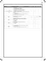
PARAMETERS CBX10224F - PA3F

19
EN
PARAMETS DESCRIPTION DEFAULT MIN MAX UNIT
12
IN.D.
(active if FP.r. dierent
from 2)
0 = deactivated
1 = barrier open light ON/OFF
2 = barrier open light proportional
- Slow ashing with barrier opening
- Quick ashing with barrier closing
- Steady light if barrier open
- 2 ashes + pause with barrier stationary (position other
than closed)
3 = Electric lock
4 = Magnetic electric lock function with output active when
barrier is closed
(tP.r.>0)
0 0 4
13
se.r.
Service interval cycle threshold.
(0 = o)
50 0 200
x 10.000
cycles
14
se.f.
Enabling of continuous ashing indicating
service required with se.r. ≠ 0 (only active with barrier
closed).
0 = o
1 = on
1 0 1
15
ST.P.
High-speed motor start-up.
0 = on
1 = o
1 0 1
16
DE.F.
1 = Restore of factory settings for sliding gate motors
SU500F
2 = Restore of factory settings for sliding barrier motor
PA3F
1 0 1

20
EN
Marantec Antriebs- und Steuerungstechnik GmbH & Co. KG produ-
ces systems for the automation of gates, garage doors, automatic
doors, roller blinds and car-park and road barriers. However, Ma-
rantec is not the manufacturer of your complete automation system,
which is the outcome of the analysis, assessment, choice of mate-
rials and installation work of your chosen installer. Every automation
system is unique, and only your installer has the experience and
skill required to produce a safe, reliable, durable system tailored to
your needs, and above all that complies with the relevant regulatory
standards. Although your automation system complies with the re-
gulation safety level, this does not rule out the presence of “residual
risk”, meaning the possibility that hazards may occur, usually due to
reckless or even incorrect use. We would therefore like to give you
some advice for the correct use of the system:
• before using the automation system for the rst time, have the in-
staller explain the potential causes of residual risks to you;
• keep the manual for future reference, and pass it on to any new
owner of the automation system;
• reckless use and misuse of the automation system may make it
dangerous: do not operate the automation system with people, ani-
mal or objects within its range of action;
• a properly designed automation system has a high level of safety,
since its sensor systems prevent it from moving with people or ob-
stacles present so that its operation is always predictable and safe.
However, as a precaution children should not be allowed to play clo-
se to the automation system, and to prevent involuntary activation,
remote controls must not be left within their reach;
• as soon as any system malfunction is noticed, disconnect the elec-
tricity supply and perform the manual release procedure. Never at-
tempt repairs on your own; call in your installation engineer. In the
meantime the door or gate can be operated without automation once
the geared motor has been released using the release key supplied
with the system. In the event of safety devices out of service arran-
ge for repairs to the automation immediately;
• in the event of malfunctions or power failures: while waiting for the
engineer to come (or for the power to be restored if your system is
not equipped with buer batteries), the door or gate can be used just
like any non-automated installation. To do this, the manual release
procedure must be carried out;
• manual release and operation: rst bear in mind that the release
procedure can only be carried out with the door or gate stationery.
• Maintenance: Like any machine, your automation system needs
regular periodic maintenance to ensure its long life and total safety.
Arrange a periodic maintenance schedule with your installation en-
gineer. Marantec recommends that maintenance checks should be
carried out every six months for normal domestic use, but this inter-
val may vary depending on the level of use. Any inspection, main-
tenance or repair work must only be carried out by qualied sta.
• Never modify the automation system or its programming and setup
parameters: this is the responsibility of your installation engineer.
• Testing, routine maintenance and any repairs must be recorded by
the person who performs them and the documents must be conser-
ved by the system’s owner.
The only procedures you are capable of, and which you are recom-
mended to perform, are cleaning of the photocell glass and removal
of any leaves or stones that may obstruct the automation system.
To prevent anyone from activating the gate or door, release the au-
tomation system before starting. Clean only with a cloth dipped in
a little water.
At the end of its useful life, the automation system must be disman-
tled by qualied personnel, and the materials must be recycled or
disposed of in compliance with the legislation locally in force.
If after some time your remote control seems to have become less
eective, or stops operating completely, the battery may be at (de-
pending on the level of use, this may take from several months up
to more than a year). You will realise this because the transmission
conrmation light does not come on, or only lights up for a very short
time.
Batteries contain pollutants: do not dispose of them with normal wa-
ste but follow the methods specied by the local regulations.
Thank you for choosing Marantec Antriebs- und Steuerungstechnik
GmbH & Co. KG; please visit our Internet site www.marantec.com
for further information.
7 - INSTRUCTIONS AND WARNINGS FOR THE END USER
A página está carregando...
A página está carregando...
A página está carregando...
A página está carregando...
A página está carregando...
A página está carregando...
A página está carregando...
A página está carregando...
A página está carregando...
A página está carregando...
A página está carregando...
A página está carregando...
A página está carregando...
A página está carregando...
A página está carregando...
A página está carregando...
A página está carregando...
A página está carregando...
A página está carregando...
A página está carregando...
A página está carregando...
A página está carregando...
A página está carregando...
A página está carregando...
A página está carregando...
A página está carregando...
A página está carregando...
A página está carregando...
A página está carregando...
A página está carregando...
A página está carregando...
A página está carregando...
A página está carregando...
A página está carregando...
A página está carregando...
A página está carregando...
A página está carregando...
A página está carregando...
A página está carregando...
A página está carregando...
A página está carregando...
A página está carregando...
A página está carregando...
A página está carregando...
A página está carregando...
A página está carregando...
A página está carregando...
A página está carregando...
A página está carregando...
A página está carregando...
A página está carregando...
A página está carregando...
A página está carregando...
A página está carregando...
A página está carregando...
A página está carregando...
A página está carregando...
A página está carregando...
A página está carregando...
A página está carregando...
A página está carregando...
A página está carregando...
A página está carregando...
A página está carregando...
A página está carregando...
A página está carregando...
A página está carregando...
A página está carregando...
A página está carregando...
A página está carregando...
A página está carregando...
A página está carregando...
A página está carregando...
A página está carregando...
A página está carregando...
A página está carregando...
A página está carregando...
A página está carregando...
A página está carregando...
A página está carregando...
A página está carregando...
A página está carregando...
A página está carregando...
A página está carregando...
A página está carregando...
A página está carregando...
A página está carregando...
A página está carregando...
A página está carregando...
A página está carregando...
A página está carregando...
A página está carregando...
A página está carregando...
A página está carregando...
A página está carregando...
A página está carregando...
A página está carregando...
A página está carregando...
A página está carregando...
A página está carregando...
A página está carregando...
A página está carregando...
A página está carregando...
A página está carregando...
A página está carregando...
A página está carregando...
A página está carregando...
A página está carregando...
A página está carregando...
A página está carregando...
A página está carregando...
A página está carregando...
A página está carregando...
A página está carregando...
A página está carregando...
A página está carregando...
-
 1
1
-
 2
2
-
 3
3
-
 4
4
-
 5
5
-
 6
6
-
 7
7
-
 8
8
-
 9
9
-
 10
10
-
 11
11
-
 12
12
-
 13
13
-
 14
14
-
 15
15
-
 16
16
-
 17
17
-
 18
18
-
 19
19
-
 20
20
-
 21
21
-
 22
22
-
 23
23
-
 24
24
-
 25
25
-
 26
26
-
 27
27
-
 28
28
-
 29
29
-
 30
30
-
 31
31
-
 32
32
-
 33
33
-
 34
34
-
 35
35
-
 36
36
-
 37
37
-
 38
38
-
 39
39
-
 40
40
-
 41
41
-
 42
42
-
 43
43
-
 44
44
-
 45
45
-
 46
46
-
 47
47
-
 48
48
-
 49
49
-
 50
50
-
 51
51
-
 52
52
-
 53
53
-
 54
54
-
 55
55
-
 56
56
-
 57
57
-
 58
58
-
 59
59
-
 60
60
-
 61
61
-
 62
62
-
 63
63
-
 64
64
-
 65
65
-
 66
66
-
 67
67
-
 68
68
-
 69
69
-
 70
70
-
 71
71
-
 72
72
-
 73
73
-
 74
74
-
 75
75
-
 76
76
-
 77
77
-
 78
78
-
 79
79
-
 80
80
-
 81
81
-
 82
82
-
 83
83
-
 84
84
-
 85
85
-
 86
86
-
 87
87
-
 88
88
-
 89
89
-
 90
90
-
 91
91
-
 92
92
-
 93
93
-
 94
94
-
 95
95
-
 96
96
-
 97
97
-
 98
98
-
 99
99
-
 100
100
-
 101
101
-
 102
102
-
 103
103
-
 104
104
-
 105
105
-
 106
106
-
 107
107
-
 108
108
-
 109
109
-
 110
110
-
 111
111
-
 112
112
-
 113
113
-
 114
114
-
 115
115
-
 116
116
-
 117
117
-
 118
118
-
 119
119
-
 120
120
-
 121
121
-
 122
122
-
 123
123
-
 124
124
-
 125
125
-
 126
126
-
 127
127
-
 128
128
-
 129
129
-
 130
130
-
 131
131
-
 132
132
-
 133
133
-
 134
134
-
 135
135
-
 136
136


Marantec CBX10224 Manual do proprietário
- Tipo
- Manual do proprietário
- Este manual também é adequado para
em outras línguas
- español: Marantec CBX10224 El manual del propietario
- français: Marantec CBX10224 Le manuel du propriétaire
- italiano: Marantec CBX10224 Manuale del proprietario
- English: Marantec CBX10224 Owner's manual
- Deutsch: Marantec CBX10224 Bedienungsanleitung
- polski: Marantec CBX10224 Instrukcja obsługi
Artigos relacionados
-
Marantec CBX20224L Manual do proprietário
-
-
-
-
-
-
-
-
Outros documentos
-
 Key Automation 580ISCT10224 Manual do usuário
-
Key Gates CT10224 Manual do usuário
-
 Key Automation 580CT20324W Manual do usuário
-
-
Key Gates CT102 Manual do usuário
-
-
 Key Automation CT202 Manual do usuário
-
 Key Automation 580ISCT202 Manual do usuário
-
 Key Automation 580IS14A Manual do usuário
-
 Key Automation 580ISCT102B Manual do usuário


