Logitech X52 Professional Space/Flight H.O.T.A.S. Guia de instalação
- Tipo
- Guia de instalação

logitechG.com
X52 PROFESSIONAL HOTAS
USER GUIDE / GUIDE D’UTILISATION


3
ENGLISH
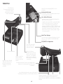
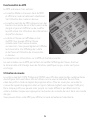
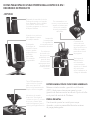
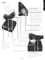
LOGITECH G X52 PROFESSIONAL SPACE/FLIGHT HOTAS PRODUCT TOUR
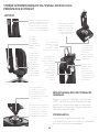
JOYSTICK
5-position
adjustment
tosuit all
handsizes.
2-Stage metal trigger
Destroy the enemy with the aid
of a precise and durable, cool-
touch trigger. Two-stages can
be programmed with separate
re functions.
Cool-touch metal
pinkie switch
can be assigned
shift functionality
todouble up on
programmable
commands.
3D Rudder Twist handle on
joystick for precise rudder
control; includes integrated
rudder lock mechanism.
Precision centering mechanism
Non-contact technology on x
and y axes and constant spring
force reduce free play, improve
control and increase durability.
3 toggle switches Spring
loaded and conveniently
positioned on the base for
an extra 6 programmable
ight commands.
Missile Launcher
Flip up the spring-loaded
safety cover to activate
missile launches.
Mode selector switch
3-position rotary
switch with tristate
LED to indicate
program mode.
3 Fire Buttons Backlit
buttons conveniently
positioned on joystick
head for instant
access in the heat
ofthe battle.
2 x 8-way hat
switches -1 pre-
dened as point
of view; select
from multiple view
perspectives and
assign frequently
used commands.
GENERAL FEATURES BACKLIGHTING
Illuminated buttons and Multi-Function Display
(MFD) - ideal for low light environments,
guaranteed to stand out from the crowd.
Adjustbrightness via Windows control panel.
METAL PARTS
Part metal construction for increased
durabilityand maximum comfort during
extended gameplay.

4
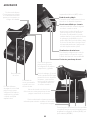
THROTTLE
2 Fire Buttons
Conveniently positioned
on throttle head for
instant access in the
heat of the battle.
Smooth-action thumb
slider provides axes for
pitch, trim and yaw
settings or zoom in/
out view.
Scroll wheel positioned on rear of throttle for
index nger activation; includes built-in button.
8-way hat switch: Select from multiple view
perspectives and assign frequently used
commands.
Clutch (I) Button
Initiates ’safe mode’ to
allow on-the-y prole
selection, or to display
button functionality on
MFD without activating
commands.
Two rotaries provide
axes for pitch, trim
and yaw settings.
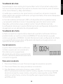
Multi-Function Display (MFD) screen
indicates:
Mode and shift state
Mode state is determined by mode selector
on the head of the stick.
User dened Text area
- indicates name of command assigned to
button when activated.
- supplies name of prole in use and enables
on-the-y prole selection. Prole can
also be changed during gameplay by
pressing clutch button and scrolling though
available proles moving the pointof- view
hat switch up and down. Move the same
button left to clear current prole or right
to activate prole.
Multi Time Displays
Time zone (set origin and destination local
times in control panel Formattable date/
month/time
Stopwatch for ight time
Progressive throttle control Super smooth action
with metal tension adjustment and detents for
programming idle (0-20%) and afterburner (80-100%)
settings.
Mouse controller,
which can also
function as a hat
switch.
Left mouse button.

5
ENGLISH
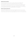
GETTING STARTED
In order for this product to function correctly please install the software from
logitech.com/support/x52-pro
MAINTAINING YOUR CONTROLLER SETTINGS
Your Logitech X52 Professional HOTAS is supplied ready for use. However, we want you to
use it in the way that suits you best. We’ve therefore included the facility for you to change
various settings on your stick and throttle units.You can, for example, vary the brightness
of the LED buttons, check your stick is working correctly or change the way the date is
displayed on your Multi-Functional Display (MFD).
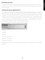
You change your controller settings in the properties window for your HOTAS. You can access
this by opening the Devices and Printers screen in Windows, right-clicking on the X52 and
then selecting Game Controllers.
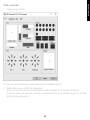
In Game Controllers select the X52 Professional HOTAS and then click Properties.
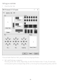
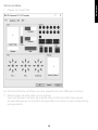
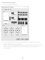
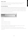
The X52 Professional HOTAS properties window consists of ve separate tabs. You can
view and change various controller settings in each tab. The settings you can change are
described in the following sections.

6
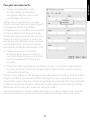
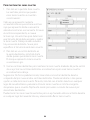
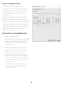
Testing your controller
1. Click the Test tab.
The controller features that you can test are displayed below.
2. Test each feature as required.
The way you do this varies, depending on what the feature does. It may, for example,
involve pressing the corresponding button, or turning the corresponding rotary control.

7
ENGLISH
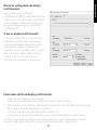
Maintaining deadzones
You can create deadzones for each range and axis your controller features move in.
Theyreduce interference that may be caused by unintended movements of the ight
stickand other controls. For example, you may want to move your stick in the X axis only,
but nd it dicult to avoid moving it in the Y axis as you do so. You can set up a deadzone
inthe Y axis so that these minor movements are not detected by the drivers.
What is a deadzone?
A deadzone is a part of the range in which an axis moves that is not detected by
thedriversand so has no eect on the game in progress. It may be around the center point
of therange, or at either end.

8
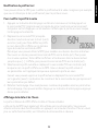
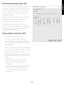
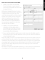
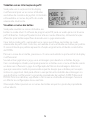
To maintain your deadzones
1. Click the Deadzone tab.
The controls you can create deadzones
forare shown, as follows:
Each axis is represented by a white box
thatcontains a red line that represents
where the control is currently sitting.
Movingthe corresponding control moves
thered line. Use this line to determine exactly
where yourdeadzone must begin and end.
Beneatheach box is a sliding scale. You use
this to specify the size of each deadzone.
2. Click on a slider on the sliding scale and
drag it to where you want the deadzone
to end. The area that represents
thedeadzone is shaded gray.
3. Use the center sliders to maintain
thedeadzone around the center point of
an axis. Use the sliders at either end to
create deadzones at either end of the axis.
Tips: By default, clicking on either the right or the left slider in the pair moves both sliders.
You can change this if you just want to adjust one side of the deadzone. To dothis,
right-click anywhere in the white box and select Link Deadzones from the popup list
ofoptions displayed. Repeat this to link the pairs of sliders again.
You can clear existing deadzones for an axis by right-clicking anywhere in the white box
andselecting Clear Deadzone.

9
ENGLISH
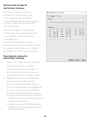
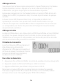
Maintaining your LED brightness
The authenticity of the ight control
experience provided by your LogitechG
X52 Professional HOTAS is enhanced
byanumber of LEDs on the throttle unit
and ight stick.
You can control the appearance of these
LEDs, making them brighter or dimmer
according to your preference.
You can also change the colour of
thedierent button LEDs, with a choice
ofgreen, amber or red for most of
thebuttons.
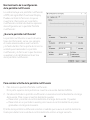
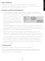
To maintain LED brightness
1. Click the LEDs tab.
A sliding scale is displayed, which you
can use to choose how brightly the LEDs
on your stick and throttle are displayed:
2. Move the slider on the scale to adjust
LED brightness. The LEDs change as
you move the slider, so you can make
sure they are as you want them to be.
Youcan either:
• Click and drag the slider along
thescale Or:
• Click a point on the scale itself,
tomove the slider in graduated steps
along the scale.

10
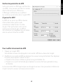
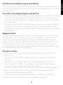
Maintaining MFD settings
Your unit includes an MFD, or Multi-
Functional Display. You can control the way
information is displayed in your MFD by
changing various settings in the MFD tab:
What is the MFD?
The MFD is a screen that displays a variety
of dierent information including, for
example, the mode currently selected and
today’s date. It is part of the same unit as
your throttle. The MFD itself and the way it
works is explained in more detail in Using
the MFD.

11
ENGLISH
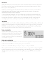
To change the brightness of your MFD
1. Click the MFD tab.
A Brightness sliding scale is displayed at the top of the tab.
2. Change the brightness of your MFD by moving the slider along the scale To move
theslider, you can either:
• Click and drag the slider along the scale. Or:
• Click a point on the scale itself, to move the slider in graduated steps along the scale.
The brightness of your MFD changes as you move the slider. Use this to determine when
theslider is in the right place.
Maintaining clock settings
Your MFD can display the current time in any time zone. You can choose the time zones
displayed and the format in which the time for each zone is displayed.
You can have up to three dierent time zones available on your MFD. Greenwich Mean Time
(GMT) is included by default. You can choose up to two additional time zones. When using
your MFD, you switch between the three time zones, as required.
To change your clock settings
1. Click the MFD tab.
This tab includes three panels in which you change the way time is displayed on
yourMFD. They are called Clock 1, Clock 2 and Clock 3.
Note: Clock 1 is set to GMT by default. You cannot change this.
2. Choose additional time zones that you want to be able to view on your MFD in the Clock
2 and Clock 3 panels. You do this by selecting an option from the corresponding Time
Adjustment drop-down list.
Each option is a time relative to GMT, for example GMT +1:00 is GMT plus one hour,
andso on. Each time is also represented by an entry in the phonetic alphabet.
Forexample, GMT is represented by ’Zulu’ and GMT +12:00 by ’Mike’.
3. Choose the format you want each time to be displayed in. To do this, either check
oruncheck the corresponding 12 Hour Format checkbox.
When the box is unchecked, the time is displayed in 24 hour clock format, i.e. between
00:00 and 23:59. If it is checked, the time is shown in 12 hour clock format.
4. Click Apply.
You can now view the current times in your chosen time zones on your MFD. See Using
the MFD for details.

12
Maintaining date settings
The current date is displayed in the bottom right-hand corner of your MFD. You can choose
how this date is displayed.
You may, for example, prefer to see the month rst, followed by day and year.
Changing the way your clutch button works
The clutch button on your throttle is used to temporarily deactivate the buttons in
thegame in progress. This enables you to check what each button does without interrupting
the game, and to select a dierent prole if required. See Viewing button names in Using
the MFD for more information.
To change the way your clutch works, check or uncheck the Latched Clutch Button checkbox
in the Clutch Settings panel and then click Apply.
When the box is checked, pressing and releasing the clutch deactivates the buttons in the
game in progress. To reactivate the buttons, you must press and release the clutch again.
When the box is unchecked, the buttons are deactivated in the game only as long as
theclutch is depressed. When you release the clutch, pressing buttons once again aects
the game in progress.

13
ENGLISH
Using the MFD
The MFD, or Multi-Functional Display, is an integral part of your throttle unit. It displays
avariety of information including button names, the current prole and today’s date.
Italsoprovides a stopwatch feature. In addition the MFD can display information and
interact with features in supported games, such as Microsoft Flight Simulator X. For more
details on this check out the nal section of this manual.
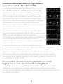
Features of the MFD
The MFD is divided into three sections:
• The mode section is at the top of the MFD and shows the currently selected mode.
SeeWorking with modes, below.
• The center section of the MFD is used to view
the names of buttons on your ight stick and
throttle, and to view and change the current
prole. See Working with prole information,
below.
• The time and date display is at the bottom
of the MFD. It can show the current time in
up to three time zones. It also includes the
stopwatch. See Viewing the time and date and
Using the stopwatch, below.
The layout of the MFD is shown right:
The controls beneath the MFD are used to change
the time display, operate the stopwatch and
interact with game-specic functions, where supported.
Working with modes
The Logitech G X52 Professional HOTAS oers extensive opportunities for you to
congure your controller to work the way you want it to. You do this by creating proles,
using the programming software. (See the programming software manual online at
logitech.com/support/x52-pro for details.) Within each prole, you can create up to six
dierent modesthat determine the actions performed when you press buttons on the ight
stick and throttle.
You can use your MFD to view the mode that is currently selected.

14
Changing the mode
You change the mode by rotating the mode selector switch on your ight stick.
Asyoudothis, the MODE number displayed on the MFD changes to reect your selection.
Using additional modes
Three modes are available by default. You can increase this to six using the pinkie switch
on your ight stick. To do this you must designate the pinkie switch to perform the same
function as the Shift key, using the SST programming software. You can then select one
ofthe additional modes by holding down the pinkie switch as you rotate the mode selector
switch. When you do this, the word SHIFT is displayed in the mode section of your MFD.
Within each prole, you can use the following modes:
• Mode 1
• Mode 2
• Mode 3
• Mode 1 + Pinkie
• Mode 2 + Pinkie
• Mode 3 + Pinkie
Viewing the current modeThe mode that is currently selected is displayed in the top part
ofthe MFD. This is shown in the following example:

15
ENGLISH
If you have selected one of the three pinkie modes described above, the word SHIFT
isdisplayed, because the pinkie switch is acting as a Shift key.
Working with prole information
You can use the center section of the MFD
toview the names assigned to buttons on
youright stick and throttle. It also shows
the names of the prole and mode currently
selected.
Viewing button names
You can view the names assigned to buttons in the current mode. You may use the SST
programming software to create a number of proles. Each prole may include up to six
dierent modes, assigning dierent functions to individual buttons for use in dierent
games.
If you’ve created proles, you can view the names you’ve given to buttons in the selected
mode in the current prole. If not, the standard name assigned to each button is displayed.
The standard name reects the function assigned to each button when your HOTAS
issupplied.

16
To view the name of a button, press it as you normally would. Its name is displayed in
thecentreline of the MFD.
If a game is in progress, use the clutch to deactivate the buttons in the game. You can then
press them and view their names without aecting the game. When supplied, the clutch
is set up so that you must keep it depressed for as long as you want the buttons to remain
inactive in the current game. You can change the way the clutch button works via the MFD
tab of the Logitech G X52 Professional HOTAS properties window. See Changing the way
your clutch button works in Maintaining your controller settings for details.
Note: You cannot view button names if the properties window is open.
Changing the current prole
You can use the MFD to change the current prole ’on the y’. You may, for example,
realisethat you’re not working in the correct prole for the game in progress.
To change the prole on the y
1. Press the clutch button. The LEDs on your clutch and on the main POV control on
youright stick begin to ash on and o. Pressing buttons does not aect the game in
progress when the clutch is engaged.
2. Move the main POV control on your ight stick up (north) or down (south) to scroll
through your proles. As you do this, the prole names are displayed in the bottom row
of the centre section of the MFD.
Note: You can use the MFD to access any folder on your computer. To open a folder,
pushthe POV to the right (east). To move up a level, scroll through the les and folders
in the current folder until [...] is displayed,
and then push the POV to the right (east).
3. Select the prole you want by moving the
main POV control right (east) when the
prole’s name is displayed on the MFD.
It becomes the current prole and its settings are applied when you resume the game
inprogress.
Tip: You can clear the current prole by moving the POV left (west). The buttons on
yourstick and throttle return to their default settings.

17
ENGLISH
4. Release the clutch. The way you do this depends on your clutch settings. Either stop
pressing the clutch button or press and release it.
Viewing the time and date
The lower part of the MFD displays the current time and date:
This part of the MFD can also be used as a stopwatch. You toggle between the two features
by pressing the Function button. See Using the stopwatch, below, for more information
about this feature.
Viewing the time
You can choose the time zone for which the current time is displayed from up to three
available time zones. To move between the available time zones, press the up (Start/Stop)
and down (Reset) buttons.
As you move between the three time zones, a number is displayed in the bottom right
corner of the MFD (in place of the date). This number disappears after a few seconds.
Greenwich Mean Time (GMT) is available by default, and is represented by the number 1.
You can choose which other time zones are available and the format in which each time is
displayed. See Maintaining clock settings in the section Maintaining your controller settings
for an explanation of this procedure.
Viewing the date
The date is displayed in the bottom right-hand corner of the MFD. By default, it is shown
in the format MMDDYY. You can change the date format, for example to DDMMYY.
See Maintaining date settings in the section Maintaining your controller settings for an
explanation of this procedure.
Using the stopwatch
The lower part of the MFD can also be used
as a stopwatch. You toggle between the
stopwatch and time displays by pressing
the Function button. When the stopwatch
isselected, the following is displayed:
To use the stopwatch
1. Press Start/Stop once. The number of seconds begins to increase.
2. Press Start/Stop again to stop the timer.
3. Press Reset to clear the time and return to 00:00.

18
Note: The timer initially shows minutes and seconds. If the time recorded reaches fty-
nine minutes and fty-nine seconds, i.e. 59:59, it changes to show hours and minutes.
Thismeans the next reading after 59:59 is 01:00.
Using the rudder lock
You can deactivate the rudder feature on your ight stick by engaging the rudder lock.
When you do this, the ight stick no longer rotates.
To use the rudder lock
1. Position your ight stick unit with the three toggle switches (T1 to T6) facing you.
Therudder lock can be seen at the base of the ight stick, on the left hand side.
Ifyoulook closer, you will see that it is labelled RLOCK.
2. Pull out the RLOCK switch. You may nd the easiest way to do this is by using the thumb
on your left hand. The twist action on the ight stick is now locked and you can no
longer rotate it. You can restore the rudder feature at any time by pushing the RLOCK
switch back in.
Adjusting the handle
You can optimise your comfort when using the ight stick by adjusting the height of the
hand rest and pinkie switch. If your hands are small, you can place the hand rest and pinkie
switch in the highest position available. This reduces the distance between the trigger switch
and pinkie switch, avoiding the need for you to stretch to reach both. If you have larger
hands, you can maximise this distance and operate the ight stick in greater comfort.
To adjust the handle
1. Position your ight stick unit with the three toggle switches (T1 to T6) facing away from
you.
A metal screw is clearly visible about one third of the way up the back of the handle.
2. Loosen the screw by turning it anti-clockwise.
When the screw is loose enough, you can move it freely up and down within its slot on
the back of the handle.
Moving the screw also moves the hand rest and pinkie switch.
3. Move the screw until the hand rest and pinkie switch are at the height you want.
4. Place the screw in the position that best suits your preferred height. There are ve
positions for you to choose from.
5. Tighten the screw in position by turning it clockwise.

19
ENGLISH
Using the Microsoft Flight Simulator X plug-in
with your Logitech G X52 Professional HOTAS
Most aircraft available in Microsoft Flight Sim X feature the radio
stack panel which is displayed and can be adjusted with the mouse
when Shift +2 is pressed. The aircraft radio stack display shows the
frequencies which communication radios are set to as well as the
Nav1 and Nav2 VOR radio beacon frequencies, ADF navigation
frequency, Distance Measuring Equipment (DME), transponder
frequency and Auto-Pilot settings. The radio stack display diers from
aircraft to aircraft but the basic information shown is the same.
First, you will need to install the plug-in for Flight Simulator
X, whichcan be found on the support page: logitech.com/
support/x52-pro. This will mean your X52 Pro is already set-up
to display and control Radio Stack information and will show the
radio stack settings when you open the Microsoft Flight Sim X
application. Please follow the instructions below to access and
change the Radio Stack.
If you have installed Flight Sim 10 after installing the HOTAS drivers,
go to C:\Program Files (x86)\Logitech\FSX Plugin and run (double
click) LogiFlightSimX.exe
From now on, every time you open Flight Sim X, your X52 Professional’s iMFD will display the
Radio Stack information. If at any time you want to disable this feature, open the run box,
from Start, run, in the run text box type
“C:\program les\Logitech\directoutput\LogiFlightSimX.exe” -uninstall
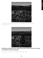
Programming the Radio Stack in Microsoft Flight Sim X
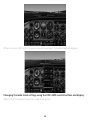
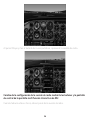
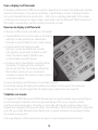
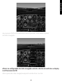
As an example, let’s assume you’re ying a Cessna C172SP Skyhawk. The cockpit view will
appear as below, with all the main aircraft altitude, airspeed and attitude instruments to
theleft, and navigational instruments to the right.

20
When you press shift and 2 on your computer keyboard, the radio stack will appear.
Changing the radio stack settings using the X52’s iMFD control buttons and display
When still on the ground, open the radio stack panel.
A página está carregando...
A página está carregando...
A página está carregando...
A página está carregando...
A página está carregando...
A página está carregando...
A página está carregando...
A página está carregando...
A página está carregando...
A página está carregando...
A página está carregando...
A página está carregando...
A página está carregando...
A página está carregando...
A página está carregando...
A página está carregando...
A página está carregando...
A página está carregando...
A página está carregando...
A página está carregando...
A página está carregando...
A página está carregando...
A página está carregando...
A página está carregando...
A página está carregando...
A página está carregando...
A página está carregando...
A página está carregando...
A página está carregando...
A página está carregando...
A página está carregando...
A página está carregando...
A página está carregando...
A página está carregando...
A página está carregando...
A página está carregando...
A página está carregando...
A página está carregando...
A página está carregando...
A página está carregando...
A página está carregando...
A página está carregando...
A página está carregando...
A página está carregando...
A página está carregando...
A página está carregando...
A página está carregando...
A página está carregando...
A página está carregando...
A página está carregando...
A página está carregando...
A página está carregando...
A página está carregando...
A página está carregando...
A página está carregando...
A página está carregando...
A página está carregando...
A página está carregando...
A página está carregando...
A página está carregando...
-
 1
1
-
 2
2
-
 3
3
-
 4
4
-
 5
5
-
 6
6
-
 7
7
-
 8
8
-
 9
9
-
 10
10
-
 11
11
-
 12
12
-
 13
13
-
 14
14
-
 15
15
-
 16
16
-
 17
17
-
 18
18
-
 19
19
-
 20
20
-
 21
21
-
 22
22
-
 23
23
-
 24
24
-
 25
25
-
 26
26
-
 27
27
-
 28
28
-
 29
29
-
 30
30
-
 31
31
-
 32
32
-
 33
33
-
 34
34
-
 35
35
-
 36
36
-
 37
37
-
 38
38
-
 39
39
-
 40
40
-
 41
41
-
 42
42
-
 43
43
-
 44
44
-
 45
45
-
 46
46
-
 47
47
-
 48
48
-
 49
49
-
 50
50
-
 51
51
-
 52
52
-
 53
53
-
 54
54
-
 55
55
-
 56
56
-
 57
57
-
 58
58
-
 59
59
-
 60
60
-
 61
61
-
 62
62
-
 63
63
-
 64
64
-
 65
65
-
 66
66
-
 67
67
-
 68
68
-
 69
69
-
 70
70
-
 71
71
-
 72
72
-
 73
73
-
 74
74
-
 75
75
-
 76
76
-
 77
77
-
 78
78
-
 79
79
-
 80
80


Logitech X52 Professional Space/Flight H.O.T.A.S. Guia de instalação
- Tipo
- Guia de instalação
em outras línguas
Artigos relacionados
-
Logitech X52 Space/Flight H.O.T.A.S. Guia de instalação
-
-
-
-
-
-
Logitech 945-000058 Manual do usuário
-
-
Logitech Flight Yoke System Guia de instalação
-
Outros documentos
-
Logitech G 945-000058 Manual do usuário
-
Thrustmaster 2960848 Manual do usuário
-
-
-
-
Thrustmaster TWCS Throttle Manual do usuário
-
 Manual del QuarkCopyDesk 8.5 Guia de usuario
-
-
Thrustmaster USB JOYSTICK Manual do usuário
-
Eaton MFD-AC-CP4 Instruction Leaflet
