3M Belt-Mounted PAPR Painter`s Kit GVP-PSK2/37335(AAD), 1 EA/Case Instruções de operação
- Tipo
- Instruções de operação

M-100 Series Respiratory Faceshields
Écrans faciaux pour système de protection
respiratoire de série M-100
Protección Facial y Respiratoria Serie M-100
Capacete Respiratório da Série M-100
M-200 Series Respiratory Faceshields
Écrans faciaux pour système de protection
respiratoire de série M-200
Protección Facial y Respiratoria Serie M-200
Capacete Respiratório da Série M-200
M-300 Series Respiratory Hard Hats
Casques durs pour système de protection
respiratoire de série M-300
Cascos con Protección Respiratoria Serie M-300
Capacete Respiratório da Série M-300
M-400 Series Respiratory Helmets
Masques pour systèmes de protection
respiratoire de série M-400
Cascos con Protección Respiratoria Serie M-400
Capacete Respiratório da Série M-300
M-Series Headgear
User Instructions for:
Pièce faciale de série M
Directives d’utilisation pour :
Casco Serie M
Instrucciones de uso para:
Equipamento para a cabeça da Série M
Instruções de Uso para:
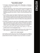
IMPORTANT: Before use, the wearer must read and understand these User Instructions. Keep
these User Instructions for reference.
IMPORTANT: Avant de se servir du produit, l’utilisateur doit lire et comprendre les présentes
directives d’utilisation. Conserver ces directives d’utilisation à titre de référence.
IMPORTANTE: Antes de su uso, el usuario debe leer y comprender estas Instrucciones de uso.
Guarde estas Instrucciones de uso para referencia futura.
IMPORTANTE: Antes de usar este produto, leia e compreenda este Instruções de Uso.
Guarde-o como referência.
Versao
TM/MC


1
ENGLISH
FOREWORD ............................................................................................................................... 2
Contact Information .................................................................................................................. 2
System Description ................................................................................................................... 2
List of Warnings within these User Instructions ......................................................................... 3
Limitations of Use ..................................................................................................................... 4
Respirator Program Management ............................................................................................ 4
NIOSH - Approval, Cautions, & Limitations ................................................................................ 4
Additional Certications ............................................................................................................ 4
OPERATING INSTRUCTIONS ........................................................................................................ 5
Unpacking................................................................................................................................. 5
Assembly ................................................................................................................................. 5
Donning & Fitting ...................................................................................................................... 6
Entering and Exiting the Contaminated Area .............................................................................. 8
INSPECTION & MAINTENANCE .................................................................................................... 9
REPLACEMENT PARTS ............................................................................................................... 9
M-925 and M-927 Visors ........................................................................................................ 10
M-920 Visor Frame & M-960 Replacement Visor Pivot Kit........................................................ 10
M-919 Visor Frame Buttons..................................................................................................... 11
M-921 Replacement Visor Gasket .......................................................................................... 12
M-957 Forehead Comfort Pad/Sweat Pad ............................................................................... 12
M-953 Ratchet ........................................................................................................................ 12
M-150 Head Suspension (M-100 & M-200 Series) .................................................................. 13
M-350 Head suspension (M-300 & M-400 Series) ................................................................. 13
M-935, M-936, & M-937 Faceseals (M-100, M-200 & M-300 Series) ..................................... 14
M-445, M-446, M-447, M-448 & M-449 Outer Shrouds (M-400 Series) .................................. 15
M-444 Inner Shrouds (M-400 Series) ...................................................................................... 15
M-116 and M-316 Airow Deectors ...................................................................................... 16
M-154 Replacement Forehead Seal (M-100 and M-200 Series) .............................................. 16
M-354 Replacement Forehead Seal (M-300 Series) ................................................................ 16
M-441 Replacement Jaw Gasket (M-400 Series) .................................................................... 16
ACCESSORIES .......................................................................................................................... 17
M-926 and M-928 Peel-off Visor Covers ................................................................................. 17
M-929 Shaded Peel-Off Cover ................................................................................................. 17
M-170 Faceshield Head Inserts ............................................................................................... 18
M-958 Chin strap .................................................................................................................... 18
M-976 Head, Neck, and Shoulder Cover (for use with M-100/M-200/M-300) .......................... 19
M-972 Flame Resistant Headgear Cover ................................................................................. 19
M-956 Size Reducing Ratchet Comfort Pad ............................................................................. 20
M-985 Headgear-Mounted Earmuff Assembly (for use with M-100/M-200/M-300) ................. 20
CLEANING, STORAGE, AND DISPOSAL ...................................................................................... 22
SPECIFICATIONS ...................................................................................................................... 23
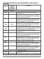
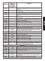
LISTING OF COMPONENTS, ACCESSORIES, AND REPLACEMENT PARTS .................................... 24
TROUBLESHOOTING ................................................................................................................. 25
WARRANTY .............................................................................................................................. 26
LIMITATION OF LIABILITY .......................................................................................................... 26
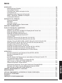
Table of Contents

2
FOREWORD
Contact Information
Read all instructions and warnings before using. Keep these User Instructions for reference. If you have
questions regarding these products contact 3M Technical service.
In United States:
Website: www.3m.com/workersafety
Technical Service: 1-800-243-4630
In Canada:
Website: www.3M.ca/Safety
Technical Service: 1-800-267-4414
System Description
The 3M™ Versao™ M-Series Headgear is a family of respirators designed to help meet the changing
needs of users through a modular design and convertibility of major components. The M-100, M-200
and M-300 Series loose tting facepieces and the M-400 Series Helmets are designed to be used with
certain 3M™ Breathing Tubes and Powered Air Purifying (PAPR) or Supplied Air (SA) units to form a
respiratory system. In addition, all 3M™ M-Series Headgear meet the test requirements of certain eye
and face protection standards, and the M-300 and M-400 Series Headgear meet test requirements
of certain industrial head protection standards. See “Approvals” section of these User Instructions for
additional information.
The M-100 Series Respiratory Faceshields have a wide-view ip-up visor, fully adjustable ratchet
suspension, and a fabric faceseal. An integral air deector allows the user to position the airow for
wearing comfort. When used with the optional M-170 Faceshield Inserts, the M-100 Series Headgear
offers lightweight head coverage from dirt, debris, and overspray as well as minimal head protection from
contact with stationary objects (i.e. “bump” protection).
The M-200 Series Respiratory Faceshields have similar features to the M-100 Respiratory Faceshields,
including a liftable wide-view visor assembly and an integral air deector to direct the airow inside the
headgear. Unlike the M-100 Series Headgear, the M-200 Series Headgear comes with a solid headgear
shell to provide lightweight head coverage from dirt, debris, and overspray as well as minimal head
protection from contact with stationary objects (i.e. “bump” protection).
The M-300 Series Respiratory Hardhats have similar features to the M-100 and M-200 Respiratory
Faceshields, including a liftable wide-view visor assembly and an integral air deector to direct the
airow inside the headgear. Unlike the M-100 Series Headgear, the M-300 Series Headgear comes
with a solid headgear shell, and unlike the M-100 or M-200 it has been tested to certain industrial head
protection standards.
The M-400 Series Helmets are designed to offer the highest level of respiratory protection of the M-Series
range. This “jawed” product provides coverage for the neck and shoulders through a versatile two piece
inner and outer neck shroud design. The M-400 Series Headgear uses the same fully adjustable head
suspension and headgear shell as the M-300 Series Headgear.
Optional accessories and a variety of faceseal, shroud, and visor materials are available for the M-Series
Headgear, giving the user a choice of congurations for specic applications.
W WARNING
Properly selected, used, and maintained respirators help protect against certain airborne contaminants
by reducing airborne concentrations in the wearer’s breathing zone below the Occupational Exposure
Limit (OEL). It is essential to follow all instructions and government regulations on the use of this
product, which includes wearing the complete respirator system during all times of exposure, in order
for the product to help protect the wearer. Misuse of respirators may result in overexposure to
contaminants and lead to sickness or death. For proper use, see supervisor, refer to the product
User Instructions or contact 3M Technical Service.

3
ENGLISH
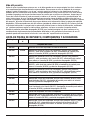
List of Warnings within these User Instructions
W WARNING
1. This product, when used as part of an approved respiratory protection system, helps protect against
certain airborne contaminants. Misuse may result in sickness or death. For proper use, see
supervisor, User Instructions or call 3M in U.S.A., 1-800-243-4630. In Canada, call Technical Service
at 1-800-267-4414.
2. These products meet the requirements of certain industrial eyewear standards and with some
models, certain industrial head protection standards. They do not provide complete head, eye, and
face protection from severe impact and penetration and are not a substitute for good safety practices
and engineering controls. Misuse may result in serious injury or death. For proper use, see
supervisor, refer to the product User Instructions or contact 3M Technical Service.
3. When exposed to eye and face hazards, wear additional eye and/or face protectors appropriate to
the hazard. ANSI Z87.1-2010, incorporated by reference in the OSHA Eye and Face Standard 29 CFR
1910.133, suggests safety spectacles or goggles should be worn in conjunction with loose tting
respirators if the visor can be raised from the normal position during use. Failure to do so may
result in serious injury or death.
4. Failure to follow these instructions may reduce the capability of the M-300 and M-400 Series
Headgear Shell to withstand impact and penetration and may result in serious injury or death:
a. Use only the cleaning processes and agents described in these User Instructions to clean the shell.
b. Do not store in direct sunlight.
c. Do not use beyond the maximum life of the product.
d. Do not use in high heat environments above the recommended maximum temperature.
5. The M-100 Series Headgear, when tted with the M-170 Faceshield Head Inserts, and the M-200
Series Headgear, do not meet the test requirements for hard hat protection under ANSI Z89.1-2009.
When head protection is required by OSHA or other safety regulations, hardhats or helmets, such as
the M-300 and M-400 Series, must be used instead of the M-100 or M-200 Series Headgear. Failure
to do so may result in serious injury or death.
6. Failure to follow these instructions may reduce the capability of the M-Series visors to withstand
impact and penetration and may result in serious injury or death:
a. Use only the cleaning processes and agents described in these User Instructions to clean the visor.
b. Ensure visor buttons are rmly secured and ush to the visor frame. Replace worn or
damaged parts.
7. Failure to follow these instructions may reduce respirator performance, overexpose you to
contaminants, and may result in sickness or death:
a. Always properly assemble and wear both the inner and outer shroud (M-400 Series).
b. Ensure visor frame rmly latches in the closed position. Replace worn or damaged parts
(M-400 Series).
c. Users must be clean-shaven where the respirator’s faceseal comes into contact with their face
(M-100, M-200 and M-300 Series).
d. The M-Series Headgear is one component of an approved respiratory protection system. Always
read and follow all User Instructions supplied with your 3M™ M-Series Headgear, PAPR Blower
Unit or Supplied Air Device in order to ensure correct system operation.
e. Do not use with parts or accessories other than those manufactured by 3M as described in these
User Instructions or on the NIOSH Approval Label for this respirator.
8. Use of the Head, Neck, and Shoulder Cover (M-976) does not increase the Assigned Protection
Factor (APF) of the M-100, M-200 and M-300 Series Headgear. The M-976 is designed to help keep
the wearer and headgear clean and does not increase the level of respiratory protection provided.
Improper use may overexpose you to contaminants, and may result in sickness or death.
9. Do not use the Head, Neck, and Shoulder Cover (M-976) or non-ame resistant faceseals and
shrouds around high heat, sparks or ames. Misuse may result in serious injury or death.
10. Do not use the Shaded Peel-Off Cover (M-929) for welding. The Shaded Peel-Off Cover (M-929)
will not protect the wearer’s eyes from the harmful level of visible light, ultra-violet radiation (UV),
and infrared radiation (IR)) resulting from gas and arc welding processes. Misuse may result in
permanent eye injury and vision loss. For welding use an ANSI Z87.1 complaint welding helmet
with an appropriate lter lens for the specic welding process.
11. Only use the Shaded Peel-Off Cover (M-929) on the 3M™ Versao™ M-Series Headgear. Do not use
on any other headgear including faceshields and eyewear. Misuse may result in permanent eye
injury and vision loss.

4
Limitations of Use
1. Do not wear this respirator to enter areas where:
a. Atmospheres are oxygen decient.
b. Contaminant concentrations are unknown.
c. Contaminant concentrations are Immediately Dangerous to Life or Health (IDLH).
d. Contaminant concentrations exceed the maximum use concentration (MUC) as determined using
the Assigned Protection Factor (APF) for the specic respirator system or the APF mandated by
specic government standards, whichever is lower. See “APF” section of these User Instructions.
Respirator Program Management
Occupational use of respirators must be in compliance with applicable health and safety standards. By
law, US employers must establish a written respiratory protection program meeting the requirements of
the OSHA Respiratory Protection Standard 29 CFR 1910.134 and any applicable OSHA substance specic
standards. For additional information on this standard contact OSHA at www.OSHA.gov. In Canada, CSA
standard Z94.4 requirements must be met and/or requirements of the applicable jurisdiction, as appropriate.
The major sections of 1910.134 are listed here for reference. Consult an industrial hygienist or call 3M
Technical Service with questions concerning applicability of these products to your job requirements.
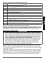
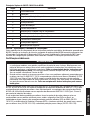
Major Sections of OSHA 29 CFR 1910.134
Section Description
A Permissible Practice
B Denitions
C Respiratory Protection Program
D Selection of Respirators
E Medical Evaluation
F Fit Testing
G Use of Respirators
H Maintenance and Care of Respirators
I Breathing Air Quality and Use
J Identication of Cartridges, Filters, and Canisters
K Training and Information
L Program Evaluation
M Recordkeeping
NIOSH - Approval, Cautions, & Limitations
These products are one component of a NIOSH approved respiratory protection system. Refer to the User
Instructions and/or the NIOSH Approval Label provided with the 3M™ Supplied Air (SA) or Powered Air
Purifying (PAPR) Blower Unit for approved congurations and applicable NIOSH Cautions and Limitations.
Additional Certications
W WARNING
1. These products meet the requirements of certain industrial eyewear standards and with some
models, certain industrial head protection standards. They do not provide complete head, eye,
and face protection from severe impact and penetration and are not a substitute for good safety
practices and engineering controls. Misuse may result in serious injury or death. For proper
use, see supervisor, refer to the product User Instructions or contact 3M Technical Service.
2. When exposed to eye and face hazards, wear additional eye and/or face protectors appropriate to
the hazard. ANSI Z87.1-2010, incorporated by reference in the OSHA Eye and Face Standard 29
CFR 1910.133, suggests safety spectacles or goggles should be worn in conjunction with loose
tting respirators if the visor can be raised from the normal position during use. Failure to do so
may result in serious injury.

5
ENGLISH
When assembled according to these User Instructions, 3M™ Headgear Assemblies Series M-100,
M-200, M-300, and M-400 meet the requirements of the ANSI Z87.1-2010 standard for eye and face
protection devices. In addition, M-300 and M-400 Series Headgear Assemblies meet the requirements of
the ANSI Z89.1-2009 (Type I, Class G) standard for industrial head protection.
Occupational use of these products for eye and face and/or head protection must be in compliance
with applicable health and safety standards. In the US, employers must comply with the OSHA personal
protective equipment (PPE) standard (29 CFR 1910.132) and, as applicable, the eye and face standard
(29 CFR 1910.133) and the head protection standard (29 CFR 1910.135). In Canada consult the
applicable standard(s) for your jurisdiction.
OPERATING INSTRUCTIONS
Unpacking
Inspect the package contents for shipping damage and ensure all components are present. The
product should be inspected before each use following the procedures in the “Inspection” section of
these User Instructions.
Assembly
M-Series Headgear
M-Series M-105, M-107, M-206, M-207, M-305, M-307, M-405, and M-407 are provided fully
assembled. Prior to use, ensure any protective covering or lm that may have been placed over the visor
to protect it during manufacturing or shipping is removed. When using the M-101, M-301, or M-401
install a visor and faceseal (M-101/301) or inner and outer shroud (M-401) prior to use following the
procedures in the “Replacement Parts and Accessories” section of these User Instructions.
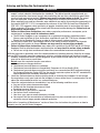
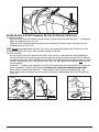
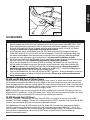
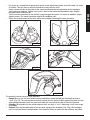
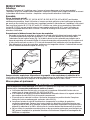
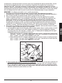
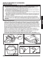
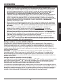
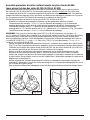
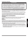
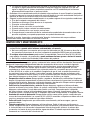
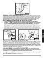
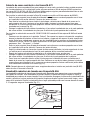
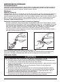
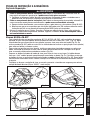
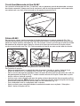
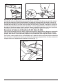
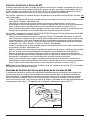
Connecting & Disconnecting Breathing Tubes
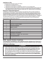
- Connect approved breathing tubes by pushing the QRS (Quick Release Swivel) end of the breathing
tube (i.e. end with the blue pinch clip) onto the air inlet of the headgear (Fig. 1a). The breathing tube
should make an audible click when attached. Verify breathing tube is secured to the headgear by
pulling on the connection. If it is not securely connected, detach and reconnect.
- To disconnect the breathing tube, compress the tabs on the end of the QRS to release and pull back
to remove (Fig. 1b).
Fig. 1a
Fig. 1b
PAPR/SA Components
Read completely and follow the assembly instructions in the User Instructions provided with your 3M™
PAPR or Supplied Air Unit.

6
Donning & Fitting
W WARNING
Failure to follow these instructions may reduce respirator performance, overexpose you to
contaminants, and may result in sickness or death:
a. Users must be clean-shaven where the respirator’s face seal comes into contact with their face
(M-100, M-200 and M-300 Series).
b. Always properly assemble and wear both the inner and outer shroud (M-400 Series).
c. Ensure visor frame rmly latches in the closed position. Replace worn or damaged parts if
required (M-400 Series).
d. The M-Series Headgear is one component of an approved respiratory protection system.
Always read and follow all User Instructions supplied with your M-Series Headgear, 3M™ PAPR
Blower Unit or Supplied Air Device in order to ensure correct system operation.
e. Do not use with parts or accessories other than those manufactured by 3M as described in
these User Instructions or on the NIOSH Approval Label for this respirator.
The following instructions cover donning and tting your 3M™ Headgear. Follow the User Instructions for
your 3M™ PAPR or Supplied Air Unit to properly assemble, don, and t your specic air source. Complete
all necessary performance checks as described in those User Instructions and verify that the airow is
adequate before donning your headgear and entering a contaminated environment.
NOTE: You may want to have a colleague help check for proper donning.
1. Connect an approved breathing tube to the headgear. See “Connecting & Disconnecting Breathing
Tubes” section for additional information.
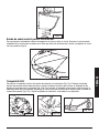
2. With the visor (lens) in the up position, place the headgear on your head.
3. Turn the ratchet knob at the back of the suspension clockwise until the suspension feels snug but
comfortable. Turn counterclockwise to loosen, if needed. The suspension ts head sizes from 51-64 cm
(US hat sizes 6 3/8 to 8). An optional size reducing ratchet comfort pad (M-956) is available to provide
additional comfort. This comfort pad also can be used to improve t and stability for smaller head sizes.
See “Replacement Parts and Accessories” section of these User Instructions for additional information.
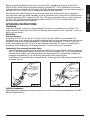
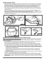
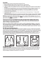
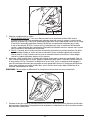
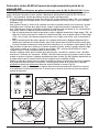
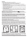
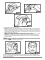
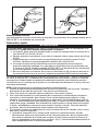
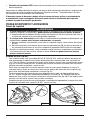
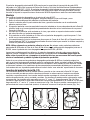
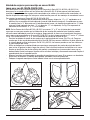
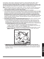
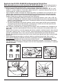
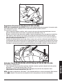
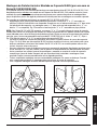
4. If the height on your head or the balance of the headgear is not comfortable, remove the headgear,
turn upside down, and adjust the suspension.
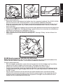
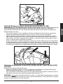
a. The suspension headband can be adjusted at four locations. There are two adjustment locations
in the rear of the headgear and two in the front. To change the position of the headband, pull the
height adjustment slot off the peg and re-position to another slot on the “ladder” (Fig. 2). Each
location can be adjusted independently for a custom t.
i. M-100 and M-200: With the headgear upside down, moving up the “ladder” will lower the
position of the headband. Moving down the “ladder” will raise it.
ii. M-300 and M-400: With the headgear upside down, moving up the “ladder” will raise the
position of the headband. Moving down the “ladder” will lower it.
Fig. 2

7
ENGLISH
b. M-100 and M-200 Series Headgear Only: The fabric straps of the M-150 Head Suspension can
be adjusted by sliding the blue strap lock located on the center strap (Fig. 3). Sliding the buckle
towards the rear of the headgear tightens the straps and will raise the height of the headgear
on the head. Sliding the buckle towards the front of the headgear loosens the straps and will
lower the height of the headgear on the head.
Fig. 3
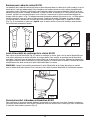
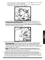
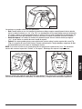
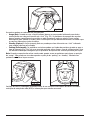
5. Lower the visor into the down position.
a. M-100, M-200 and M-300: Pull down on the loop located on the faceseal. Ensure the visor is fully
down and covering your face. The headgear should sit level on your head with the faceseal gently
hugging your face. If using the M-985 Earmuff Assembly or M-976 Head, Neck, and Shoulder
Cover, ensure it does not interfere with the faceseal. The elasticized edge of the faceseal should
come into contact with the skin under the chin and around the jaw.
b. M-400: Ensure visor is rmly closed (completely latched) in the down position. You should hear an
audible “click” when it is fully closed. Tighten the adjustable cord on the inner shroud until there is
less than a two nger gap between your skin and the inner shroud. Leave the outer shroud draped
over your shoulders.
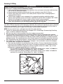
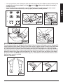
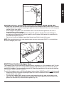
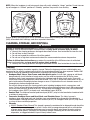
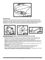
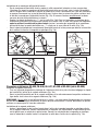
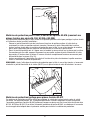
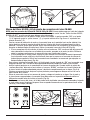
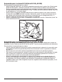
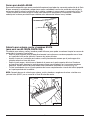
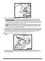
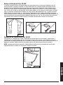
6. If needed, adjust the airow inside the headgear for wearing comfort. To adjust, raise the visor into
the up (open) position. Locate the blue air deector in the front of the headgear and rotate. Fig. 4
shows where the air deector is located. There are two positions. Adjust fully open for more airow
across the face or partially closed to re-direct a portion of the air towards the visor. After adjusting the
air deector, lower the visor back into the down position.
NOTE: Do not adjust the air deector while in a contaminated area.
Fig. 4
7. Complete any nal performance checks required according to the User Instructions for your PAPR or
Supplied Air Unit before entering a contaminated area.

8
Entering and Exiting the Contaminated Area
W WARNING
1. These products meet the requirements of certain industrial eyewear standards and with some
models, certain industrial head protection standards. They do not provide complete head, eye,
and face protection from severe impact and penetration and are not a substitute for good safety
practices and engineering controls. Misuse may result in serious injury or death. For proper
use, see supervisor, refer to the product User Instructions or contact 3M Technical Service.
2. When exposed to eye and face hazards, wear additional eye and/or face protectors appropriate to
the hazard. ANSI Z87.1-2010, incorporated by reference in the OSHA Eye and Face Standard 29
CFR 1910.133, suggests safety spectacles or goggles should be worn in conjunction with loose
tting respirators if the visor can be raised from the normal position during use. Failure to do so
may result in serious injury.
3. Failure to follow these instructions may reduce respirator performance, overexpose you to
contaminants, and may result in sickness or death.
a. The M-Series Headgear is one component of an approved respiratory protection system.
Always read and follow all User Instructions supplied with your 3M™ M-Series Headgear, PAPR
Blower Unit or Supplied Air Device in order to ensure correct system operation.
4. Do not use the head, neck, and shoulder cover or non-ame resistant faceseals and shrouds
around high heat, sparks or ames. Misuse use may result in serious injury or death.
5. Failure to follow these instructions may reduce the capability of the M-300 and M-400 Series
Headgear Shell to withstand impact and penetration and may result in serious injury or death:
a. Do not use in high heat environments above the recommended maximum temperature.
With the respirator in operation, enter the contaminated area, breathing normally. Keep the air supply
hose or PAPR assembly away from equipment, vehicles, and other physical and chemical hazards.
1. Airborne contaminants which can be dangerous to your health include those that are so small you
may not be able to see or smell them.
2. Do not wear this respirator to enter areas where:
a. Atmospheres are oxygen decient.
b. Contaminant concentrations are unknown.
c. Contaminant concentrations are Immediately Dangerous to Life or Health (IDLH).
d. Contaminant concentrations exceed the maximum use concentration (MUC) determined using
the Assigned Protection Factor (APF) for the specic respirator system or the APF mandated by
specic government standards, whichever is lower.
3. Leave the contaminated area before reaching inside or removing the headgear. Do not remove
the respirator or reach your hand into the headgear in areas where the air is contaminated. Do not
adjust the airow deector while in a contaminated area.
4. Leave the contaminated area immediately if any of the following conditions occur:
a. Any part of the system becomes damaged.
b. Airow into the respirator decreases or stops.
c. Breathing becomes difcult.
d. You feel dizzy or your vision is impaired.
e. You taste or smell contaminants.
f. Your face, eyes, nose or mouth become(s) irritated.
g. You suspect that the concentration of contaminants may have reached levels at which this
respirator may no longer provide adequate protection.
Refer to the “Inspection & Maintenance” section of these User Instructions for guidance on how to
properly care for your M-Series Headgear.

9
ENGLISH
INSPECTION & MAINTENANCE
W WARNING
1. Failure to follow these instructions may reduce respirator performance, overexpose you to
contaminants, and may result in sickness or death.
a. Do not use with parts or accessories other than those manufactured by 3M as described in
these User Instructions or on the NIOSH Approval Label for this respirator.
2. Failure to follow these instructions may reduce the capability of the M-300 and M-400 Series
Headgear Shell to withstand impact and penetration and may result in serious injury or death:
a. Do not use beyond the maximum life of the product.
Before and after each use, inspect entire headgear for signs of damage or wear including dents,
rips, cracks, color changes, chalking, fading, aking and penetration. Carefully inspect all headgear
components including the following:
• Visor and visor frame: Look for scratches or other visual distortions that could make it difcult to
see through the visor. Look for signs that the visor has warped or cracked. A warped visor may not t
properly into the headgear and on the M-400 Series may not seal against the jaw. Ensure the visor
stays rmly in the up (open) and down (closed) positions. Ensure visor buttons are present, rmly
secured, and ush to the visor frame. Examine the visor gasket for tears or other damage. Gasket
should be pliable and not brittle.
• Head suspension: Look for cracks, rips, fading, or other damage. Ensure head suspension ratchet
operates properly. Inspect the web straps for rips, tears, fraying, or fading. Look for worn stitching.
Ensure straps are properly attached.
• Faceseal or inner and outer shroud: Look for tears, holes, stretched elastic, gaps in seams, damage to
stitching or other damage. Examine the gasket for tears or other damage. The gasket should be pliable
and not brittle. Ensure faceseal or inner and outer shroud is securely and properly attached. Inspect the
zipper of the inner shroud and ensure shroud is completely attached to outer shroud.
• Headgear shell: Look for visible damage including dents, cracks, color change, chalking or fading.
Any M-300/M-400 Headgear subjected to impact should be removed from service and replaced even
if damage is not readily apparent.
• Forehead seals: Ensure they are properly and securely attached and are free from damage.
• Breathing tube: Look for tears, holes or cracks. Bend the tube to verify that it is exible. Ensure the
gasket located in the QRS is present and not damaged. Inspect the gasket located on the bayonet
end of the breathing tube (i.e. end that connects to the air source) for signs of damage. The breathing
tube should t rmly into the air source connection.
• PAPR blower assembly: Inspect according to the User Instructions for your specic air source.
Inspect date codes on visors, shells, and other plastic components and ensure parts have not exceeded
their maximum life. See “Expected Life” section of these User Instructions for additional information.
If you discover any signs of wear and/or damage, remove headgear from use and service or
replace as appropriate. Failure to do so may affect respirator performance and reduce the degree
of protection provided.
REPLACEMENT PARTS AND ACCESSORIES
Replacement Parts
W WARNING
1. Failure to follow these instructions may reduce the capability of the M-Series visors to
withstand impact and penetration and may result in serious injury or death:
a. Ensure visor buttons are rmly secured and ush to the visor frame. Replace worn or damaged
parts if required.
2. Failure to follow these instructions may reduce respirator performance, overexpose you to
contaminants, and may result in sickness or death.
a. Always properly assemble and wear both the inner and outer shroud (M-400 Series).
b. Do not use with parts or accessories other than those manufactured by 3M as described in
these User Instructions or on the NIOSH Approval Label for this respirator.
3. Do not use the head, neck, and shoulder cover or non-ame resistant faceseals and shrouds
around high heat, sparks or ames. Misuse may result in serious injury or death.

10
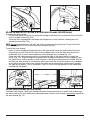
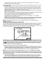
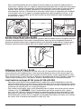
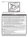
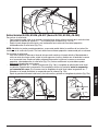
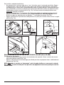
M-925 and M-927 Visors
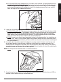
- With the visor frame in the down position (M-100, M-200 & M-300), release the visor frame buttons by
pushing the buttons outward from inside the visor frame, one “click” (Fig. 5a). Move the visor frame to
the up (open) position and pull on visor to remove from frame (Fig. 5b). If using the M-400, it may be
easier if the visor frame is in the up (open) position to release the buttons and remove the visor.
- With the visor in the up (open) position, install a new visor by inserting visor into the groove in the
frame, lining up the notches in the visor with the visor frame buttons. Ensure visor is fully seated in
the groove (Fig. 5b).
- Push visor frame buttons closed to lock visor in place. The buttons should make an audible “click”
when fully seated in the frame (Fig. 5c). Ensure visor buttons are rmly secured and ush to the visor
frame (Fig. 5d). If the buttons do not seat ush to frame, remove and reinsert.
- Ensure the visor gasket is present and securely inserted into the groove in the top of the visor frame
(See “M-921” in this section).
Fig. 5a
Fig. 5b
Fig. 5c
X
Fig. 5d
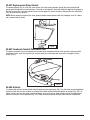
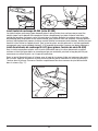
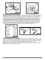
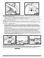
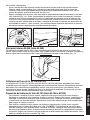
M-920 Visor Frame & M-960 Replacement Visor Pivot Kit
NOTE for M-100, M-200 & M-300 Series users: You must rst detach the faceseal from the suspension
headband. Re-attach faceseal before use. See “M-935, M-936, & M-937 Faceseals” in this section for
additional information.
- Fig. 6a shows the pivot kit. From the top down, the part marked “3M” is the post (1), the next part is
the “back plate” (2), and the bottom part in the Fig. 6a is the “metal spring clip” (3).
- With the headgear upside down and the visor frame in the up (open) position, pull down on metal
spring clips (towards inside of headgear) until they touch the back plate. Pull out to remove. Gently
use a tool if necessary (e.g. at-blade screwdriver). Remove frame from M-Series Headgear (Fig. 6b).
• If replacing frame or pivot kit, remove post with red “3M” from visor frame by placing the frame on
the edge of a table, resting on the post (i.e. 3M is facing toward you), and press down forcefully on
the visor frame with heel of hand.
• If replacing pivot kit, push back plate out from shell slightly (towards outside of headgear) and
slide out from slot on headgear shell to remove. Gently use a tool if necessary (e.g. at-blade
screwdriver) (Fig. 6c).
- To re-install the visor frame and pivot kit, insert “3M” post into visor frame. Ensure “3M” is positioned
such that it is right side up when worn and not upside down.
- Install back plate into the headgear shell. When installing the “wind mill” pattern should be facing
outwards and the “M-960” marking will be located on the bottom of the plate. Install rounded edge
rst and slide completely into the slot (Fig. 6d). Gently push down on back plate to ensure it is ush to
bottom of slot.

11
ENGLISH
- Line up visor frame over attachment slots and slide spring into place. With the post and back plate
engaged, the visor frame should be in the fully open or fully closed position before the spring is
installed (Fig. 6e).
- Verify the visor frame and pivot kit is correctly installed by raising and lowering the visor several
times. Ensure the visor stays rmly in the up (open) and down (closed) positions.
Fig. 6a
1
2
3
Fig. 6b
Fig. 6c
Fig. 6d
Fig. 6e
M-919 Visor Frame Buttons
The visor frame buttons are designed to stay slotted in the visor frame until broken, worn or damaged. To
replace broken or worn buttons, move the visor frame to the up (open) position. Remove visor from frame
as described in the previous section. Remove worn or broken button(s). Gently use a tool if necessary
(e.g. pliers) to assist in removal. Install new buttons one at a time, ensuring they are correctly aligned on
each side of the frame. Fig. 7a shows how the buttons should be positioned (i.e. sloped at tops are both
pointed in towards each other and not outwards on the frame). Re-install visor and ensure visor buttons
are rmly secured and ush to the visor frame (Fig. 7b). If the buttons do not seat ush to frame, check
that they were correctly installed.
Reinstall if necessary.
Fig. 7a
X
Fig. 7b

12
M-921 Replacement Visor Gasket
To remove gasket (Fig. 8), with the visor frame in the up (open) position, grasp the black gasket and
slowly pull straight out in small sections. To install a new gasket, align end with the edge of the groove in
the top of the visor. Press the gasket rmly into the groove in small sections. Both gasket ribs should be
fully inserted into the groove.
NOTE: When properly installed, the visor gasket should make contact with the headgear shell. If it does
not, remove and re-install.
Fig. 8
M-957 Forehead Comfort Pad/Sweat Pad
To replace comfort pad, unsnap pad and remove from headband. Wrap new comfort pad around the
headband in the area that comes into contact with your forehead and secure by closing the three
snaps (Fig. 9).
Fig. 9
M-953 Ratchet
To remove the ratchet, locate ratchet attachment points on suspension (Fig. 10a). Remove by pressing down
on each of the four circular sections to release the ratchet at the attachment points as shown (Fig. 10b). To
install ratchet, rst turn the knob counterclockwise as far as it will go. Hold ratchet so that the attachment
holes are curved in the up position (Fig. 10c). Snap attachment points on each side onto the suspension.

13
ENGLISH
Fig. 10a
Fig. 10b
Fig. 10c
M-150 Head Suspension (M-100 & M-200 Series)
To replace head suspension:
- Detach the faceseal and forehead seal button from the suspension headband. See “M-935, M-936,
& M-937 Faceseals & M-154 Forehead Seal” in this section for additional information.
- Release the suspension from the headgear by pulling the height adjustment slot off the peg at each
of the four attachment points. Fig. 11 points to one of the attachment slots. There are 2 in the rear
and 2 in the front.
- Install new suspension by snapping each of the four height adjustment slots onto the four pegs on the
headgear shell. NOTE: See “Donning and Fitting” section of these User Instructions for information on
adjusting the suspension for a comfortable t (Fig. 11).
- Attach faceseal and forehead seal button to suspension.
- Adjust suspension for t and comfort according to the “Donning & Fitting” section of these User
Instructions.
Fig. 11
M-350 Head suspension (M-300 & M-400 Series)
NOTE for M-300 Series users: You must rst detach the faceseal from the suspension headband. See
“M-935, M-936, & M-937 Faceseals” in this section for additional information.
To replace head suspension:
- With the headgear upside down, release the head suspension from the headgear shell by pushing
upwards on the plastic hangers of the web straps. The hangers are shown in Fig. 12.
- Remove the remaining center web strap by pushing upwards on the plastic hangers.
- To install new suspension, attach the single web strap that is not attached to the headband into the
headgear shell by inserting the hangers into the slots. The center strap attaches in the slots next to
the 3M™ Pivots.
- Align the head suspension over the shell with the ratchet towards the air inlet and the comfort
pad end of the suspension towards the visor. Attach the plastic hangers of the suspension into the
remaining slots to complete installation of the suspension. All hangers must be attached. Ensure
hangers are fully seated and ush to shell slot.

14
Fig. 12
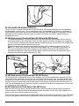
M-935, M-936, & M-937 Faceseals (M-100, M-200 & M-300 Series)
To remove faceseal:
- With the visor frame in the down (closed) position, remove plastic faceseal tab from “T” attachment
points on headband (Figs. 13a & b).
- Grasp the black faceseal gasket and slowly pull straight out in small sections, working your way
around the faceseal (Fig. 13c).
NOTE: Do not bend gasket over and ‘peel’ off as this may damage the gasket ribs. Do not start in the
middle of the gasket. Pull out in small sections starting at one end.
To install faceseal:
- On the faceseal, locate the side with the fabric “loop” which is sewn into the elastic. Holding the
faceseal with this side facing up, grasp the black gasket on the faceseal and align with the edge of
the groove in the visor frame. Starting with one edge, press the gasket rmly into the groove in small
sections, working your way around the faceseal (Fig. 13c). Both gasket ribs should be fully inserted
into the groove.
- Locate the “T” hooks on the suspension (Fig. 13d). The plastic tab of the faceseal attaches to this hook
on the suspension. To attach, slide the tabs in between the suspension and the headgear shell.
Attach notch in faceseal tabs onto the “T” hooks located on the suspension headband (Fig. 13b).
- Grasp elastic loop on faceseal and pull up over suspension headband and attach to the plastic tab
(Fig. 13a).
Fig. 13a
Fig. 13b

15
ENGLISH
Fig. 13c
Fig. 13d
M-445, M-446, M-447, M-448 & M-449 Outer Shrouds (M-400 Series)
To remove the outer shroud:
- Pull the large plastic tab off the air inlet of the headgear and release the suspension ratchet from the
hole in the outer shroud (Fig. 14a).
- Grasp the black shroud gasket and slowly pull straight out in small sections, working your way
around the shroud (Fig. 14b).
NOTE: Do not bend gasket over and ‘peel’ off as this may damage the gasket ribs. Do not start in the
middle of the gasket. Pull out in small sections starting at one end.
To install the outer shroud:
- Insert air inlet of headgear through the hole in the large plastic tab on the outer shroud. Push tab
fully onto the air inlet such that it is ush to the headgear shell. Push the ends of the plastic tab
underneath shell lip. Insert head suspension ratchet through hole in shroud (Fig. 14a).
- Grasp the black shroud gasket and pull to expose the edge of the gasket where it meets the
elastic (Fig. 14c). Align the edge of the gasket with the edge of the groove in the headgear. Press
the gasket rmly into the groove in small sections, working your way around the shroud. Start at
one end and work around in one direction. When you reach the end of the groove in the headgear
on the other side from where you started, the gasket on the shroud may extend slightly beyond
the edge of the groove - this is acceptable - but it is critical that both gasket ribs are completely
inserted into the groove.
Fig. 14a
Fig. 14b
Fig. 14c
M-444 Inner Shrouds (M-400 Series)
To remove inner shroud, unzip inner shroud from outer shroud and remove. To install inner shroud, align
the zipper parts on the inner and outer shroud and connect. Ensure inner shroud is completely zipped into
the outer shroud (Fig. 15).

16
Fig. 15
M-116 and M-316 Airow Deectors
The M-116 (M-100 and M-200) and M-316 (M-300 and M-400) airow deectors are not intended to
be removed on a regular basis. They are designed to stay in the headgear until broken or damaged. To
replace broken parts, move the visor to the up (open) position. With the headgear upside down, remove
damaged or broken airow deector. Gently use a tool if necessary (e.g. pliers). Install deector by
snapping into place.
M-154 Replacement Forehead Seal (M-100 and M-200 Series)
- To remove forehead seal, lift visor frame into the up (open) position and unbutton the seal from its
attachment points on the suspension. Grasp the black gasket and slowly and gently pull straight out
in small sections, starting at one end and working around the gasket. Do not start in the middle of the
gasket as this may cause the gasket to rip or tear.
- To install forehead seal, grasp the black gasket and align with headgear according to Fig. 16a.
NOTE: The “shiny” side of the seal should be facing towards you (i.e. outwards) as you install the
seal. Press the gasket rmly into the groove in small sections. Both gasket ribs should be fully
inserted into the groove. Grasp fabric tab with button and fold over to inside of suspension. Attach
forehead seal button to head suspension (Fig. 16b).
Fig. 16a
Fig. 16b
M-354 Replacement Forehead Seal (M-300 Series)
The forehead seals are designed to stay in the headgear and are not intended to be removed until they
need replacement. Completely remove current seals before installing new ones. If needed, gently hand
scrape off any residue. Clean the surfaces with a respirator wipe or damp cloth and wipe dry with towel.
Ensure surfaces are completely clean and dry before installing new forehead seals. Install one seal at a
time. Peel off backing from seal. Hold seal in place in appropriate location with hand pressure for at least
5-10 seconds to ensure adhesion.
M-441 Replacement Jaw Gasket (M-400 Series)
With the visor in the up (open) position grasp the black gasket and slowly and gently pull straight out
in small sections, starting at one end and working around the gasket. Do not start in the middle of the
gasket as this may cause the gasket to rip or tear.
To install new gasket, align end with the edge of the groove in the bottom of visor frame. Press the gasket
rmly into the groove in small sections. Both gasket ribs should be fully inserted into the groove (Fig. 17).

17
ENGLISH
Fig. 17
ACCESSORIES
W WARNING
1. The M-100 Series Headgear, when tted with the M-170 Faceshield Head Inserts, and the M-200
Series Headgear do not meet the test requirements for hard hat protection under ANSI Z89.1-2009.
When head protection is required by OSHA, or other safety regulations, hardhats or helmets, such
as the M-300 and M-400 Series Headgear, must be used instead of the M-100 or M-200 Series
Headgear. Failure to do so may result in serious injury or death.
2. Use of the Head, Neck, and Shoulder Cover (M-976) does not increase the Assigned Protection
Factor (APF) of the M-100, M-200 or M-300 Series Headgear. The M-976 is designed to help keep
the wearer and headgear clean and does not increase the level of respiratory protection provided.
Improper use may overexpose you to contaminants, and may result in sickness or death.
3. Do not use the Head, Neck, and Shoulder Cover or non-ame resistant faceseals and shrouds around
high heat, sparks or ames. Misuse use may result in serious injury or death.
4. Do not use the Shaded Peel-Off Cover (M-929) for welding. The Shaded Peel-off Cover (M-929)
will not protect the wearer’s eyes from the harmful level of visible light, ultra-violet radiation (UV),
and infrared radiation (IR)) resulting from gas and arc welding processes. Misuse may result in
permanent eye injury and vision loss. For welding use an ANSI Z87.1 complaint welding helmet
with an appropriate lter lens for the specic welding process.
5. Only use the Shaded Peel-Off Cover (M-929) on the 3M™ Versao™ M-Series Headgear. Do not use
on any other headgear including faceshields and eyewear. Misuse may result in permanent eye
injury and vision loss.
M-926 and M-928 Peel-off Visor Covers
Ensure the visor is clean and dry before attaching any visor covers. To attach peel-off visor covers, peel
off the paper backing from the adhesive on the edges of the cover. Center the cover over the visor and
press the edges with the adhesive coating against the visor. You may stack up to 5 visor covers on top of
one another. This allows you to quickly peel off covers as they become difcult to see through, reducing
the number of times you must stop working to reapply covers.
NOTE: The M-926 covers are for use with the M-925 uncoated visor and the M-928 covers are for use
with the M-927 coated visor. The M-926 covers have a notch in the tab for easy identication. Use of the
M-928 covers on the uncoated M-925 visor may leave residue upon removal.
M-929 Shaded Peel-Off Cover
The 3M™ Versao™ Shaded Peel-off Visor Cover (M-929) is an optional accessory for the 3M™
Versao™ M-Series Headgear. The peel-off is optimized for the M-927 premium visor. Use of the M-929
cover on the uncoated M-925 visor may leave residue upon removal.
The shaded peel-off cover M-929 complies with the shade W3.0 transmission requirements listed in
Table 6 of the American Standards Institute Eye and Face Protection standard ANSI Z87.1-2010. The
peel-off cover is intended for use in torch brazing and soldering applications. For additional information
on the technical specications, consult the M-929 Technical Specications Sheet available at
www.3m.com/workersafety.

18
Assembly
To attach the peel-off cover to the outside of the M-927 visor:
1. Before installing the peel-off cover, ensure the visor is clean and dry.
2. Remove the paper backing from the adhesive on the edges of the cover.
3. Center the cover over the outside of the visor and press the edges with the adhesive coating against
the visor.
4. If the peel-off is being attached to a visor not yet installed into the M-Series Headgear Assembly, insert
the visor into the headgear following the procedures in the M-Series Headgear User Instructions.
5. Verify the peel-off is centered on the visor and there is minimal gap between the visor frame
assembly and the peel-off cover.
6. If the peel-off is not centered on the visor, remove the peel-off and repeat steps 1-5 above with a
new peel-off cover.
7. Read completely and follow the User Instructions for the M-Series Headgear and your 3M™ Supplied
Air Device or powered air purifying respirator to complete system assembly and performance checks.
NOTE: Use only one peel-off cover at a time. Do not stack multiple M-929 shaded peel-off covers on
the M-Series Visor. Do not use any other peel-off cover in combination with the M-929 including the clear
peel-off visor covers M-926 and M-928.
Carefully inspect the peel-off for damage before each use including holes, tearing, ripping, peeling,
discoloration, and hazing. If you discover any signs of damage, remove headgear from use and
replace the peel-off visor cover with a new one. Failure to do so may affect performance and
reduce the degree of protection provided.
Before use, store the M-929 shaded peel-off covers in original unopened packaging in a clean area
that is protected from contamination, damage, dirt, debris, product distortion, and direct sunlight. Do
not store next to furnaces, ovens, or other sources of high heat. When stored in accordance with the
recommended storage conditions listed in these User Instructions, product may be used until “use by”
date specied on packaging.
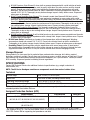
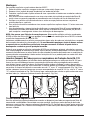
M-170 Faceshield Head Inserts
The head inserts can be snapped into the M-100 Series Headgear to create a closed shell that provides
minimal head coverage against contact with stationary objects or hard surfaces. The inserts also help to
protect the wearer’s head from overspray, dust, dirt and debris. The inserts can be installed and removed
as required. The inserts are marked with an “X” and an “O” respectively (Fig. 18a). To install, match
the marking on the insert with the corresponding marking on the M-100 shell (i.e. match “X” to “X”) as
shown in Fig. 18b. Snap into place, starting with the snap on the outside of the shell on each side (i.e.
side nearest wearer’s ears) (Fig. 18c).
X
Fig. 18a
X
X
O
O
Fig. 18b
Fig. 18c
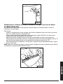
M-958 Chin strap
An optional chin strap is available for all M-Series Headgear to increase stability and provide additional
comfort. Locate the chin strap attachment points on the head suspension and attach the chin strap as
shown in Fig. 19. Verify chin strap is secured to the suspension by pulling on the chin strap. See Chin
Strap packaging for additional information on use and care.
A página está carregando...
A página está carregando...
A página está carregando...
A página está carregando...
A página está carregando...
A página está carregando...
A página está carregando...
A página está carregando...
A página está carregando...
A página está carregando...
A página está carregando...
A página está carregando...
A página está carregando...
A página está carregando...
A página está carregando...
A página está carregando...
A página está carregando...
A página está carregando...
A página está carregando...
A página está carregando...
A página está carregando...
A página está carregando...
A página está carregando...
A página está carregando...
A página está carregando...
A página está carregando...
A página está carregando...
A página está carregando...
A página está carregando...
A página está carregando...
A página está carregando...
A página está carregando...
A página está carregando...
A página está carregando...
A página está carregando...
A página está carregando...
A página está carregando...
A página está carregando...
A página está carregando...
A página está carregando...
A página está carregando...
A página está carregando...
A página está carregando...
A página está carregando...
A página está carregando...
A página está carregando...
A página está carregando...
A página está carregando...
A página está carregando...
A página está carregando...
A página está carregando...
A página está carregando...
A página está carregando...
A página está carregando...
A página está carregando...
A página está carregando...
A página está carregando...
A página está carregando...
A página está carregando...
A página está carregando...
A página está carregando...
A página está carregando...
A página está carregando...
A página está carregando...
A página está carregando...
A página está carregando...
A página está carregando...
A página está carregando...
A página está carregando...
A página está carregando...
A página está carregando...
A página está carregando...
A página está carregando...
A página está carregando...
A página está carregando...
A página está carregando...
A página está carregando...
A página está carregando...
A página está carregando...
A página está carregando...
A página está carregando...
A página está carregando...
A página está carregando...
A página está carregando...
A página está carregando...
A página está carregando...
A página está carregando...
A página está carregando...
A página está carregando...
A página está carregando...
A página está carregando...
A página está carregando...
A página está carregando...
A página está carregando...
A página está carregando...
A página está carregando...
A página está carregando...
A página está carregando...
A página está carregando...
A página está carregando...
-
 1
1
-
 2
2
-
 3
3
-
 4
4
-
 5
5
-
 6
6
-
 7
7
-
 8
8
-
 9
9
-
 10
10
-
 11
11
-
 12
12
-
 13
13
-
 14
14
-
 15
15
-
 16
16
-
 17
17
-
 18
18
-
 19
19
-
 20
20
-
 21
21
-
 22
22
-
 23
23
-
 24
24
-
 25
25
-
 26
26
-
 27
27
-
 28
28
-
 29
29
-
 30
30
-
 31
31
-
 32
32
-
 33
33
-
 34
34
-
 35
35
-
 36
36
-
 37
37
-
 38
38
-
 39
39
-
 40
40
-
 41
41
-
 42
42
-
 43
43
-
 44
44
-
 45
45
-
 46
46
-
 47
47
-
 48
48
-
 49
49
-
 50
50
-
 51
51
-
 52
52
-
 53
53
-
 54
54
-
 55
55
-
 56
56
-
 57
57
-
 58
58
-
 59
59
-
 60
60
-
 61
61
-
 62
62
-
 63
63
-
 64
64
-
 65
65
-
 66
66
-
 67
67
-
 68
68
-
 69
69
-
 70
70
-
 71
71
-
 72
72
-
 73
73
-
 74
74
-
 75
75
-
 76
76
-
 77
77
-
 78
78
-
 79
79
-
 80
80
-
 81
81
-
 82
82
-
 83
83
-
 84
84
-
 85
85
-
 86
86
-
 87
87
-
 88
88
-
 89
89
-
 90
90
-
 91
91
-
 92
92
-
 93
93
-
 94
94
-
 95
95
-
 96
96
-
 97
97
-
 98
98
-
 99
99
-
 100
100
-
 101
101
-
 102
102
-
 103
103
-
 104
104
-
 105
105
-
 106
106
-
 107
107
-
 108
108
-
 109
109
-
 110
110
-
 111
111
-
 112
112
-
 113
113
-
 114
114
-
 115
115
-
 116
116
-
 117
117
-
 118
118
-
 119
119
-
 120
120


3M Belt-Mounted PAPR Painter`s Kit GVP-PSK2/37335(AAD), 1 EA/Case Instruções de operação
- Tipo
- Instruções de operação
em outras línguas
Artigos relacionados
-
3M Versaflo™ Air Duct Sealing Ring EA/Case Instruções de operação
-
3M Faceseal 527-01-15R10, 10 EA/Case Manual do usuário
-
3M Welding Inner Shroud W-8220, 1 EA/Case Instruções de operação
-
3M Adapter L-170 4 EA/Case Manual do usuário
-
3M Hood BE-10BR, (Formerly 522-02-23R01), Butyl Rubber, 1 EA/Case Instruções de operação
-
3M Single Station Battery Charger Kit TR-341N, PAPR 1 EA/Case Instruções de operação
-
-
3M Adflo™ Powered Air Purifying Respirator PAPR Battery 15-1099-07/37146(AAD), 1 EA/Case Instruções de operação
-
-
Outros documentos
-
Ski-Doo EXOME HELMET Manual do usuário
-
-
Bell Motorcycle Helmet Manual do proprietário
-
Bell SRT Series Manual do usuário
-
GYS PROTECTIVE GOGGLES (SHADE 5) - Blister Ficha de dados
-
-
 Giro Helmet Manual do usuário
-
Husqvarna HP500C-01 Manual do proprietário
-
Crivit SP - 2 Manual do proprietário
-
MSA Gallet F1 XF Instruções de operação
