3M Welding Inner Shroud W-8220, 1 EA/Case Instruções de operação
- Tipo
- Instruções de operação

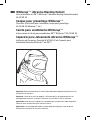
3 Whitecap™ Abrasive Blasting Helmet
User Instructions for 3M™ Whitecap™ Abrasive Blasting Helmet Assembly
W-8100B-CA
Casque pour grenaillage Whitecap™
Directives d’utilisation pour l’ensemble casque pour grenaillage
W-8100B-CA Whitecap™ 3M™
Careta para sandblasteo Whitecap™
Instrucciones de Careta para sandblasteo 3M™ Whitecap™ W-8100B-CA
Capacete para Jateamento Abrasivo Whitecap™
Instruções de Uso para o Conjunto W-8100B-CA de Capacete para
Jateamento Abrasivo Whitecap™ da 3M™
Important: Read and understand all safety information before operating. Keep these User
Instructions for reference.
Important : Avant de se servir du produit, l’utilisateur doit lire et comprendre tous les
renseignements relatifs à la sécurité. Conserver ces directives à titre de référence.
Importante: Antes de usar el equipo, lea y entienda toda la información sobre seguridad.
Conserve estas Instrucciones para referencia futura.
Importante: Leia e compreenda todas as informações de segurança antes de operar.
Guarde estas Instruções de Uso para referência.

2

3
ENGLISH
TABLE OF CONTENTS
GENERAL SAFETY INFORMATION........................................................................................................ 4
– Intended Use ................................................................................................................................. 4
– List of Warnings and Cautions within these User Instructions ......................................................... 4
USE INSTRUCTIONS AND LIMITATIONS ............................................................................................... 6
– Do Not Use For .............................................................................................................................. 6
– Respirator Selection and Training ................................................................................................... 6
– NIOSH Approval ............................................................................................................................. 6
– NIOSH Cautions and Limitations ..................................................................................................... 6
– Eye, Face and Head Protection ....................................................................................................... 6
– Head Protection ............................................................................................................................. 7
– Glossary of Terms .......................................................................................................................... 7
– Assigned Protection Factor ............................................................................................................ 7
SPECIFICATIONS ................................................................................................................................ 8
– Expected Useful Life ..................................................................................................................... 8
COMPONENTS AND REPLACEMENT PARTS ........................................................................................ 8
– 3M™ Helmet Assembly Components ............................................................................................ 9
– 3M™ Replacement Parts ............................................................................................................ 10
ASSEMBLY ...................................................................................................................................... 12
– Head Suspension Installation ....................................................................................................... 12
– Chin Strap Installation .................................................................................................................. 13
– Shroud Attachment ...................................................................................................................... 13
– Faceshield Assembly ................................................................................................................... 14
– Breathing Tube Assembly ............................................................................................................ 17
– Supplied Air Components Assembly ............................................................................................ 17
OPERATING INSTRUCTIONS ............................................................................................................. 17
– Assemble the Respirator System ................................................................................................. 18
– Inspect the Respirator Condition Thoroughly ................................................................................ 18
– User Performance Check ............................................................................................................ 18
– Don the Respirator ....................................................................................................................... 19
– Enter the Contaminated Area ....................................................................................................... 20
– Exit the Contaminated Area .......................................................................................................... 20
INSPECTION, CLEANING AND STORAGE ............................................................................................ 20
– Inspection .................................................................................................................................... 20
– Cleaning ...................................................................................................................................... 23
– Storage ....................................................................................................................................... 23
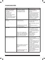
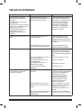
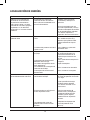
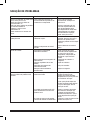
TROUBLESHOOTING ......................................................................................................................... 24
IMPORTANT NOTICE ......................................................................................................................... 25
FOR MORE INFORMATION ................................................................................................................ 25

4
GENERAL SAFETY INFORMATION
Intended Use
This helmet is a component of certain 3M™ Respirator systems approved by NIOSH for use as a
type CE, continuous flow-supplied air respirator for abrasive blasting. This respirator is not approved
for entry into, or escape from atmospheres immediately dangerous to life and health (IDLH). These
respirators are intended to help protect the wearer by reducing the inhalation of, impact of, and
abrasion by materials used or generated in abrasive blasting. This helmet is designed for use in many
types of abrasive blasting operations, including blasting with shot, sand and other media.
This respirator helps protect against certain airborne contaminants.
Misuse may result in sickness or death. For proper use, see
supervisor, or User Instructions, or call 3M in U.S.A., 1-800-243-4630.
In Canada, call Technical Service at 1-800-267-4414.
List of Warnings and Cautions within these User Instructions
WARNING
– This respirator helps protect against certain airborne contaminants. Misuse may result in
sickness or death. For proper use, see supervisor, or User Instructions, or call 3M in U.S.A.,
1-800-243-4630. In Canada, call Technical Service at 1-800-267-4414.
– Each person using this respirator must read and understand the information in these User
Instructions before use. Use of these respirators by untrained or unqualified persons, or use
that is not in accordance with these User Instructions, may adversely affect respirator
performance and may result in sickness or death.
– 3M™ Abrasive Blasting Helmet Assemblies meet the requirements of the ANSI Z87.1-2003,
high impact option. 3M recommends additional eye protection, such as safety spectacles or
goggles, be worn in conjunction with this headgear. This helmet helps provide limited face and
eye protection against certain flying particles. Misuse may result in serious personal injury,
including blindness, or death.
– Do not use with parts or accessories other than those manufactured by 3M as described in these
User Instructions or on the NIOSH approval label for this respirator. Do not attempt to repair or
modify any component of the system except as described in these User Instructions. Failure to do
so may adversely affect respirator performance and result in sickness or death.
– Use of this respirator in atmospheres for which it was not designed may result in sickness or
death. Do not wear this respirator to enter areas where:
– Atmospheres are oxygen deficient.
– Contaminant concentrations are unknown.
– Contaminant concentrations are Immediately Dangerous to Life or Health (IDLH).
– Contaminant concentrations exceed 1000 times the applicable exposure limit (the assigned
protection factor for this respirator system) or the APF mandated by specific government
standards, whichever is lower.
WARNING

5
ENGLISH
WARNING
– Contaminants that are dangerous to your health include those that you may not be able to see or
smell. Leave the contaminated area immediately if any of the following conditions occur. Failure
to do so may result in sickness or death.
– Any part of the system becomes damaged.
– Airflow into the respirator decreases or stops.
– Breathing becomes difficult.
– You feel dizzy or your vision is impaired.
– You taste or smell contaminants.
– Your face, eyes, nose or mouth become(s) irritated.
– You suspect that the concentration of contaminants may have reached levels at which this
respirator may no longer provide adequate protection.
– If this respirator fails any of the requirements of the user inspection and performance check, do
not use the respirator until all necessary repairs have been made and the respirator passes the
performance check. Failure to do so may adversely affect respirator performance and result
in sickness or death.
– Failure to pass a user performance check and complete all necessary repairs before use may
adversely affect respirator performance and result in sickness or death.
– Your employer must provide compressed breathing air that meets at least the requirements
of the specification for Grade D breathing air as described in the Compressed Gas Association
Commodity Specification G-7.1-1997 in the United States. In Canada, refer to CSA standard
Z180.1, table for the quality of compressed breathing air. Failure to do so may result in
sickness or death.
– You must comply with OSHA standard 29 CFR 1910.134, which states that “Airline couplings
shall be incompatible with outlets for other gas systems to prevent inadvertent servicing of
airline respirators with nonrespirable gases or oxygen.” Failure to do so may result in sickness
or death.
– Do not remove the respirator while in a contaminated area. Always don and remove the
respirator in a clean environment. Failure to do so may expose the wearer to respiratory hazards
and could result in sickness and/or death.
– Before you enter a hazardous atmosphere wearing this respirator, you must inspect the
respirator, complete a user performance check, and don the respirator according to the
instructions in the “Operating Instructions” section of these User Instructions and the User
Instructions provided with the components of the system you are using. Failure to do so may
adversely affect respirator performance and may result in sickness or death.
– Use of this respirator system to enter areas where atmospheric concentrations of contaminants
are unknown, immediately dangerous to life or health, exceed the Maximum Use Concentration
(MUC) for the respirator headpiece, or where atmospheres contain less than 19.5% oxygen
could result in sickness and/or death.
– Do not use strong solvents such as aromatic hydrocarbons or ketones to clean the headgear
shell. These solvents can cause deterioration of the shells’ ability to withstand impact and
penetration. Use of these solvents for cleaning may result in injury or death.

6
USE INSTRUCTIONS AND LIMITATIONS
Do Not Use For
Respiratory protection when atmospheric concentrations of contaminates are unknown or immediately
dangerous to life or health, or in atmospheres containing less than 19.5% oxygen.
Respirator Selection and Training
Use of these respirators must be in accordance with applicable health and safety standards, respirator
selection tables contained in such publications as American National Standards Institute (ANSI) Z88.2-
1992, Canadian Standards Association (CSA) Standard Z94.4 or pursuant to the recommendations of
an industrial hygienist. The employer must have a written respirator program in place that complies
with the Occupational Safety and Health Administration (OSHA) respiratory standard 29 CFR 1910.134
prior to using any respirator. In Canada, follow CSA standard Z94.4 or the requirements of the authority
having jurisdiction in your region.
Before use, the employer must assure that each respirator user has been trained by a qualified person
in the proper use and maintenance of the respirator and air supply components according to the
instructions contained in these User Instructions and other applicable User Instructions.
WARNING
WARNING
Each person using this respirator must read and understand the information in these User
Instructions before use. Use of these respirators by untrained or unqualified persons, or use that
is not in accordance with these User Instructions, may adversely affect respirator performance
and may result in sickness or death.
NIOSH Approval
For a listing of the components of NIOSH approved 3M™ Abrasive Blasting Respirator Systems, refer
to the NIOSH approval label, which accompanies the supplied air valves.
NIOSH Cautions and Limitations
This headgear is one component of a NIOSH approved respirator system. Refer to User Instructions
provided with the approved supplied air valves for the listing of the appropriate Cautions and
Limitations.
Eye, Face and Head Protection
Note: Users must evaluate their specific occupational hazards and choose products appropriate for
eye, face and head hazards in the workplace.
3M™ Abrasive Blasting Helmet Assemblies meet the requirements of the ANSI Z87.1-2003, high
impact option. 3M recommends additional eye protection, such as safety spectacles or goggles, be
worn in conjunction with this headgear. This helmet helps provide limited face and eye protection
against certain flying particles. Misuse may result in face and/or eye injury.

7
ENGLISH
Head Protection
When assembled and used according to these User Instructions, the 3M helmet assemblies meet the
requirements of ANSI Z89.1-2003 Type I, Class E head protection. This helmet helps provide limited
head protection against impact and penetration and contact with electrical conductors.
Glossary of Terms
APF—Assigned Protection Factor. The expected level of respiratory protection that would be provided
in the workplace by a properly functioning respirator to properly fitted and trained
users. Always expressed as a multiple of the permissible exposure limit (“PEL”) for the
contaminant from which you are seeking protection.
PEL—Permissible Exposure Limit. The maximum allowable concentration of a contaminant in the air
to which an individual may be exposed. These may be time-weighted averages, short-term
limits, or ceiling limits.
Abrasive blasting respirator—a respirator designed to help protect the wearer from inhalation of,
impact of, and abrasion by materials used or generated in abrasive blasting.
Airline respirator—an atmosphere-supplying respirator in which the breathing air is not designed to be
carried by the wearer (also called a type “C” supplied air respirator ).
Breathing air—respirable air that meets at least the specification for Grade D breathing air, as
described in the Compressed Gas Association Commodity Specification G-7.1-1997 in the
United States. In Canada, refer to CSA standard Z180.1, table for the quality of compressed
breathing air.
Continuous flow respirator—an atmosphere supplying respirator which provides a continuous flow of
breathing air to the respiratory inlet covering.
Helmet—a respiratory inlet covering which completely covers the head and neck and portions of the
shoulders and which offers head protection against impact and penetration.
Immediately dangerous to life or health (IDLH)—any atmosphere which poses an immediate hazard to
life or poses immediate, irreversible debilitating effects on health.
Respiratory inlet covering—that portion of a respirator that connects the wearer’s respiratory tract to
an air-purifying device or breathing air source, or both.
Type “C” supplied-air respirator—an airline respirator for entry into and escape from atmospheres not
immediately dangerous to life or health (“IDLH”) which consists of a source of respirable
breathing air, a hose, a detachable coupling, a control valve, orifice, a demand valve,
or pressure demand valve, an arrangement for attaching the hose to the wearer, and a
facepiece, hood or helmet.
Type “CE” supplied-air respirator—a type “C” supplied air respirator equipped with additional
devices designed to protect the wearer’s head and neck against impact and abrasion from
rebounding abrasive material, and with shielding material such as plastic, glass, woven
wire, sheet metal, or other suitable material to protect the window(s) of facepieces, hoods,
and helmets which do not unduly interfere with the wearer’s vision and permit easy access
to the external surface of such window(s) for cleaning.
Assigned Protection Factor
3M supports an assigned protection factor (APF) of 1,000 for this helmet, which is consistent with
the OSHA APFs defined in 29 CFR 1910.134. According to OSHA, “The employer must have evidence
provided by the respirator manufacturer that testing of these respirators demonstrates performance
at a level of protection of 1,000 or greater to receive an APF of 1,000. 3M Technical Data Bulletin
#175 describes the test procedures and data supporting an APF of 1,000 for 3M hoods and helmets.
Technical Data Bulletins are available on the 3M web site, www.3M.com/OccSafety. In Canada, follow
CSA Z94.4 or the requirements of the authority having jurisdiction in your region.

8
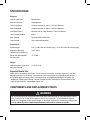
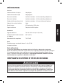
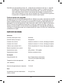
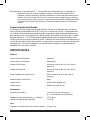
SPECIFICATIONS
Materials
Helmet Outer Shell Polyethylene
Helmet Inner Shell Polypropylene
Outer Faceshield Cellulose acetate @ .040 in (.102 cm) thickness
Inner Faceshield Cellulose acetate @ .040 in (.102 cm) thickness
Faceshield Covers Polyester film @ .004 thickness (.10 cm) thickness
Outer Faceshield Brim Nylon
Inner Shroud Polyester 65%/Cotton 35%
Outer Shroud Vinyl-laminated polyester
Performance
Airflow Range 6 to 15 cubic feet per minute [cfm] (170 to 425 liters per minute [lpm])
Maximum Operating 140ºF (60ºC)
Temperature (ambient air)
Noise level generated by 74-78 dB
the respirator
Weight
Helmet Assembly with Inner 5.2 lb (2.4 kg)
and Outer Shroud
Expected Useful Life
When used in accordance with these User Instructions, the useful life of the respirator is variable
depending on the use conditions. The respirator can be maintained for extended periods of time
by replacing worn or broken parts in accordance with the inspection procedures outlined in the,
“Inspection, Cleaning and Storage” section. Perform the User Performance Check outlined in the
“Operating Instructions” section before each use.
COMPONENTS AND REPLACEMENT PARTS
Do not use with parts or accessories other than those manufactured by 3M as described in these
User Instructions or on the NIOSH approval label for this respirator. Do not attempt to repair or
modify any component of the system except as described in these User Instructions. Failure to do
so may adversely affect respirator performance and result in sickness or death.
WARNING

9
ENGLISH
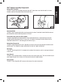
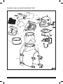
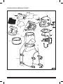
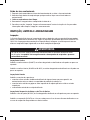
3M™ Helmet Assembly Components
Helmet Shell Assembly
The 3M™ Helmet Shell Assembly consists of the 3M™ Outer Shell, Inner Shell W-8005, Air Guide
W-8004, and Inner Faceshield Gasket Kit W-8030 (Fig. 1).
Inner Faceshield
The 3M™ Inner Faceshield W-8160 is held in place by the Inner Faceshield Gasket W-8030 and must
be used with the abrasive blasting helmet at all times.
Faceshield Frame and Latch Kit Assembly
The outer faceshield frame holds the 3M™ Outer Faceshield W-8101, Faceshield Covers W-8102,
and Abrasive Blasting Screen W-8115 or W-8116. The frame is held onto the outer helmet shell by
faceshield latches W-8111 and locking pins W-2849-2 (Fig. 2).
Helmet Head Suspension
The 3M™ Head Suspension W-2878-2 provides a minimum safe clearance between the helmet shell
and the head. The suspension allows adjustment for head size, depth and balance.
Chin Strap
The 3M™ Chin Strap W-2913-2 is hooked to the inside of the helmet to assist in securing the helmet
to the wearer.
Inner Shroud
The 3M™ Inner Shroud W-8020-2 attaches to base of the outer helmet shell. The inner shroud may be
worn inside the work shirt to allow air to flow over the torso for added comfort.
Outer Shroud
The 3M™ Outer Shroud W-8052 secures to the base of the outer helmet shell.
Fig. 1 Fig. 2

10
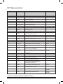
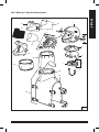
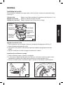
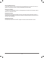
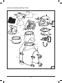
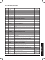
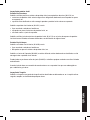
3M™ Replacement Parts
Item Number Product Number Description Quantity Required
1 - Helmet Shell 1
2 W-2849-2 Locking Pins 2
3 W-8111 Latch Mounting Kit (includes item 2) 1
4 W-8004 Air Guide 1
5 W-8005 Inner Shell Assembly 1
6 W-2871-5 Crown Strap Assembly (5 pack) 1
7 W-2870-5 Sweatband (5 pack) 1
8 W-2878-2/07041* Head Suspension (2 pack) 1
- W-2879 Rachet Suspension Optional, Not Shown
- W-3261 Rachet Kit Optional, Not Shown
9 W-2913-2 Chin Strap (2 pack) 1
10 - Gasket Strap (part of item 14) 1
11 W-8032
Gasket Screw Kit (16 screws 14)
and threaded post, part of item
1
12 W-8031-5 Faceshield Clip 19 (5 pack, part of item 14) 1
13 - Gasket (part of item 14) 1
14 W-8030 Gasket Kit (includes items 10, 11, 12, 13) 1
15 W-8160-10 Inner Faceshield (10 pack) 1
16 W-8101-10 Outer Faceshield (10 pack) 1
17 W-8102-25 Faceshield Cover (25 pack or 250 pack) Optional
19 W-8116-2
Heavy Duty Faceshield Screen, for shot blasting (2
pack)
Optional
20 W-8110
Frame and Latch Assembly (includes
items 2 and 3, see also item 21)
1
21 W-8113-4
Faceshield Frame Gasket Kit (includes 4 each
replacement upper gaskets and 4 each left and right
side gaskets)
Not Shown
22 W-8020-2 Inner Shroud, Standard, cotton (2-pack) 1
23 W-8021-2 Inner Shroud, Double Cuffed, cotton (2-pack) Alternate
24 W-8061 Shroud Clamp, stainless steel 1
25 W-8057-2
Outer Shroud, Extended Length (waist length, does
not include shroud clamp), (2-pack)
1
26 W-8052
Outer Shroud Assembly, Extended Length
(waist length, with shroud clamp)
(includes items 24 and 25)
1
26 W-8062 Heavy Duty Outer Shroud, Waist Length Alternate
_ W-8112
Faceshield Frame Assembly
(includes items 16, 17 and 21)
1
-- W-8056-2 Shroud, Standard Length
Alternate
Not shown
-- W-8051 Shroud Assembly, Standard Length
Alternate
Not shown
* 07041 is an automotive product number for W-2878-2.

11
ENGLISH
17
19
16
20
24
25
9
8
5
4
6
7
26
22
23
15
14
12 13 11
3
2
1
Fig. 3
3M™ Whitecap™ Abrasive Blasting Helmet

12
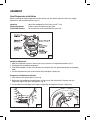
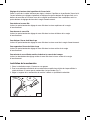
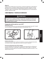
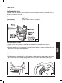
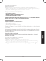
ASSEMBLY
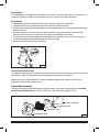
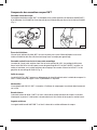
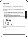
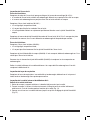
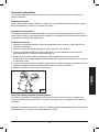
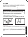
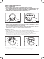
Head Suspension Installation
Before installing the head suspension into the helmet, you will need to adjust the head size, height
adjustment, and faceshield distance (Fig. 4).
Head size Adjust the headband to fit hat sizes from 6
1
/2 to 8.
Height adjustment Raise or lower the helmet on your head.
Faceshield distance Set the distance of the faceshield from your face.
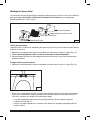
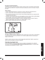
Head Size Adjustment
1. Hold the suspension system in front of you so you face the size adjustment buttons (Fig. 5).
2. Disengage the size adjustment buttons.
3. Slide the headband in or out to the desired size and push the size adjustment buttons in the proper
holes.
4. Put the suspension on your head to check the fit. Readjust if necessary.
Suspension into Helmet Installation
1. Place helmet shell upside down in your lap.
2. Make sure the headband size adjustment is at the rear of the helmet shell. Securely seat the
suspension lugs in the inner shell pockets (Fig. 6).
3. Try the helmet on and check the fit. Adjust suspension for height or balance, if necessary.
8
7
3
/
4
7
1
/
2
7
1
/
4
7
Fig. 4
Fig. 5 Fig. 6

13
ENGLISH
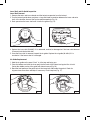
Height and Faceshield Distance Adjustment
Remove the head suspension from the inner shell whenever you wish to change the height, balance
or faceshield distance of the helmet. These adjustments can be made simply by moving the four
adjustment buttons on the top of the headband into different holes in the crown strap. To begin,
disengage each of the 4 headband adjustment buttons from the holes in the crown strap.
To position the headband lower on your head:
Snap each of the 4 headband adjustment buttons into the top holes of the crown strap.
To position the headband higher on your head:
Snap each of the 4 headband adjustment buttons into the bottom holes of the crown strap.
To move the faceshield away from your face:
Snap each of the 4 headband adjustment buttons into the front holes of the crown strap.
To move the faceshield closer to your face:
Snap each of the 4 headband adjustment buttons into the back holes of the crown strap.
To tilt the headband so that the nape strap fits lower on the back of your neck:
Snap the back 2 headband adjustment buttons into the back holes of the crown strap.
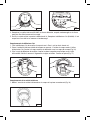
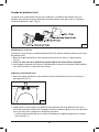
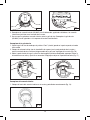
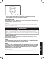
Chin Strap Installation
1. Hold the helmet shell upside down in your lap.
2. Fasten hooks on the ends of the chin strap through the small holes on each side of the inner shell.
Make sure the chin strap is not twisted (Fig. 7).
3. Adjust the length of the chin strap for a comfortable fit.
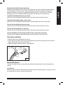
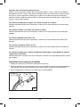
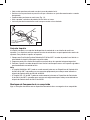
Shroud Attachment
The inner and outer shrouds are secured to the outside of the helmet shell for easy attachment and
removal.
Inner Shroud
Stretch the elastic band over the bottom of the helmet and into the shroud groove. Line up the seam of
the shroud with the seam on the front of the helmet.
Fig. 7

14
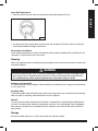
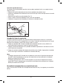
Shroud Clamp
The shroud clamp is designed to secure both inner and outer shrouds to the helmet. This consists of a
stainless steel band and quick release clamp to assist in shroud installation and removal.
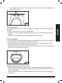
Outer Shroud
1. Feed the open end of the shroud band into the slit on the right of the shroud collar.
2. Thread the band of the shroud through the collar and out the other opening.
3. Lift the screw clamp up and insert the belt into the slot below the screw. Insert excess band into the
shroud slit (Fig. 8).
4. Position the seam of the outer shroud to match up with the seam on the inner shroud and then
place the shroud over the inner shroud in the groove at the bottom of the helmet.
5. Lift up on the screw clamp and push the band against the shroud to take up the excess. Push the
screw clamp down and slide the band over the slit on the right.
6. Tighten the screw clamp using a screwdriver.
Shroud Clamp Quick Release
To release the shroud clamp, simply loosen the screw one to two turns and then push the screw clamp
up to free the band. The shrouds can then be removed for cleaning or replacement.
Replace the inner or outer shroud if it is worn or damaged. Replace the shroud clamp if it will no
longer secure the shrouds to the helmet.
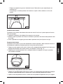
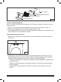
Faceshield Assembly
The abrasive blasting faceshield screens, faceshield covers and the outer faceshield are all installed
inside the faceshield frame for the 3M™ Whitecap™ Abrasive Blasting Helmet (Fig. 9).
Outer Faceshield
Faceshield Covers
Faceshield Screen
Faceshield Frame
Fig. 8
Fig. 9

15
ENGLISH
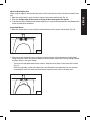
Abrasive Blasting Screens
When using the optional abrasive blasting screen (W-8116) place the screen into the faceshield frame
first.
1. Move the swivel locks at each end of the frame to the center and the back (Fig. 10).
2. Place the straight edge of the screen at the top of the frame against the gasket.
3. To protect the outer faceshield, 3M recommends that a single faceshield cover be used between the
screen and the outer faceshield.
Faceshield Covers
1. Move the swivel locks at each end of the faceshield frame to the center and the back (Fig. 10).
2. Place one to five faceshield covers inside the faceshield frame with the perforated straight edge
facing the gasket. When the top cover becomes unserviceable, remove each one by pulling outward
and then across in one quick motion.
- There are two tabs perforated into the cover(s). Keep the small tab(s) on the inside of the frame
(Fig. 11).
- Push the large tab(s) to the front side of the frame. Bend each one separately for easy removal.
- To prolong the life of the outer faceshield, do not remove the last cover in the work area.
Fig. 10
Fig. 11

16
Outer Faceshield
The outer faceshield fits inside the frame with the straight edge at the top of the frame against the gasket.
1. Insert the faceshield under the locks at one end.
2. While holding the faceshield against the faceshield covers, press the other end of the faceshield
into place.
3. Reposition the swivel locks over the faceshield to secure in place.
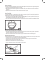
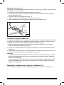
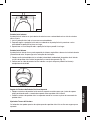
Inner Faceshield
The inner faceshield is a required part of the respirator system and must be in place during abrasive
blasting. Always follow these installation instructions:
1. Place either the top (straight edge) or bottom (rounded edge) of the inner faceshield into the inner
faceshield gasket attached to the helmet shell (Fig. 12).
2. Start at one side of the faceshield and work it into the gasket until the faceshield is completely installed.
Attaching the Faceshield Frame to the Helmet
• Placethefaceshieldframeagainstthehelmetandshroudssothatthefoamgasketispositioned
against the helmet shell above the inner faceshield.
• Securethefaceshieldframetothehelmetusingthefaceshieldlatchesandlockingpins.
Adjusting the Frame Latch
The frame latches may need adjustment when the faceshield frame does not fit securely to the helmet.
• Loosenthetwoscrewsundereachofthefaceshieldlatches.
• Slidethelatchesforwardorbackwarduntiltheframetssecurelyagainstthehelmetshell.
• Tightenthetwoscrewsoneachlatch(Fig.13).
• Reattachthefaceshieldframeandclosethelatches.
• Insertalockingpinintoeachlatchtoholdthelatchclosed.
Fig. 12
Fig. 13

17
ENGLISH
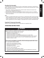
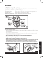
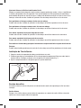
Breathing Tube Assembly
The breathing tube carries breathing air from the air control device on the wearer’s waist belt to the
helmet. Breathing air enters the helmet through the air inlet on the back of the helmet shell. To attach
the breathing tube to the helmet:
1. Place a 3M™ Thumbscrew Clamp W-5102 around the smooth, flexible cuff at the end of the
breathing tube. Do not tighten the clamp, yet.
2. Push the smooth, flexible cuff of the breathing tube onto the helmet air inlet as far as possible.
3. Position the clamp around the smooth, flexible cuff and then hand tighten the clamp by turning the
thumb screw clockwise.
Note:
– The 3M™ Breathing Tube W-8003 may be used only in conjunction with 3M™ W-Series Air Control
Devices approved for use with this headgear as referenced in the W-Series Air Control NIOSH label.
– The 3M™ Breathing Tube GVP-122 may be used only in conjunction with 3M™ V-Series Air Control
Devices approved for use with this headgear as referenced in the V-Series Air Control NIOSH label.
Supplied Air Components Assembly
Follow the instruction provided with the air control devices and supplied air hose.
OPERATING INSTRUCTIONS
Use of this respirator in atmospheres for which it was not designed may result in sickness or
death. Do not wear this respirator to enter areas where:
– Atmospheres contain hazardous vapors or gasses.
– Atmospheres are oxygen deficient.
– Contaminant concentrations are unknown.
– Contaminant concentrations are Immediately Dangerous to Life or Health (IDLH).
– Contaminant concentrations exceed 1000 times the applicable exposure limit (the assigned
protection factor for this respirator system) or the APF mandated by specific government
standards, whichever is lower.
Contaminants that are dangerous to your health include those that you may not be able to see or
smell. Leave the contaminated area immediately if any of the following conditions occur. Failure to
do so may result in sickness or death.
– Any part of the system becomes damaged.
– Airflow into the respirator decreases or stops.
– Breathing becomes difficult.
– You feel dizzy or your vision is impaired.
– You taste or smell contaminants.
– Your face, eyes, nose or mouth become(s) irritated.
– You suspect that the concentration of contaminants may have reached levels at which this
respirator may no longer provide adequate protection.
WARNING

18
Failure to pass a user performance check and complete all necessary repairs before use may
adversely affect respirator performance and result in sickness or death.
Find the approved pressure range for the length of hose you are using from the label on the air control
device or from the appropriate air control device User Instructions.
Read the pressure gauge located where you are attaching the compressed air hose to the source of
breathing air to verify that the pressure is within the approved range. Adjust the pressure, as needed,
within that range. Connect the supplied air hose to the breathing air source. Air should begin flowing.
Place your hand inside the headgear, in the area above the faceshield. You should feel the air entering
the headgear.
Check to be sure that the breathing tube is securely clamped over the helmet air inlet and connected to
the air control device securely, according to the User Instructions for the air control device you are using.
Put the respirator on your head so that the faceshield is directly in front of your face.
Pull the suspension firmly onto your head. Turn your head from side to side, then nod your head up
and down. If the suspension does not fit your head snugly or if the height on your head or the balance
of the headgear is not comfortable, remove the headgear and adjust the suspension according to the
“Assembly” section of these User Instructions.
Secure the chin strap if necessary for greater stability.
WARNING
WARNING
If this respirator fails any of the requirements of the user inspection and performance check, do
not use the respirator until all necessary repairs have been made and the respirator passes the
performance check. Failure to do so may adversely affect respirator performance and result in
sickness or death.
If you have any doubts about the applicability of this equipment to your job situation, consult an
industrial hygienist or call 3M Occupational Health and Environmental Safety Division, Technical
Service, in U.S.A. at 1-800-243-4630. In Canada, call Technical Service at 1-800-267-4414.
Assemble the Respirator System
Read completely and follow the assembly instructions in the “Assembly” section of these User
Instructions and the User Instructions provided with the air control device and supplied air hose you
are using.
Inspect the Respirator Condition Thoroughly
Each time the respirator is used, you must complete the inspection procedures recommended in
the “Inspection, Cleaning and Storage” section and the procedures included in the User Instructions
provided with the air control device you are using.
User Performance Check

19
ENGLISH
WARNING
Your employer must provide compressed breathing air that meets at least the requirements of the
specification for Grade D breathing air as described in the Compressed Gas Association Commodity
Specification G-7.1-1997 in the United States. In Canada, refer to CSA standard Z180.1, table for
the quality of compressed breathing air. Failure to do so may result in sickness or death.
You must comply with OSHA standard 29 CFR 1910.134, which states that, “Airline couplings
shall be incompatible with outlets for other gas systems to prevent inadvertent servicing of airline
respirators with nonrespirable gases or oxygen.” Failure to do so may result in sickness or death.
Don the Respirator
Do not remove the respirator while in a contaminated area. Always don and remove the respirator in a
clean environment. Failure to do so may expose the wearer to respiratory hazards and could result in
sickness or death.
1. Verify that the respirator is connected to the proper air source and that air is flowing before donning
the respirator.
2. Verify that the air pressure at the point where the air supply hose is attached to the air source is in
the required range of the air control device.
3. Put the respirator on your head so that the faceshield is directly in front of your face.
4. Pull the suspension firmly onto your head. If the suspension does not fit your head snugly or if the
height on your head or the balance of the headgear is not comfortable, remove the headgear and
adjust the suspension according to the, “Assembly” section of these User Instructions.
5. Pull the chin strap under your chin. If the chin strap does not fit snugly, remove the headgear and
adjust the strap according to the “Assembly” section of these User Instructions.
6. With the helmet on your head, pull the inner shroud down around the shoulders or tuck it inside
your shirt. Tucking the inner shroud inside your shirt may allow air to flow over your upper body for
greater comfort.
7. Pull the outer shroud down in the front and back. To keep the outer shroud in the proper position,
pull the elastic straps on the front panel of the outer shroud around the side of your body and fasten
the metal clips to the D-rings on the back panel of the outer shroud.
Check to be sure that the compressed air hose is not kinked or twisted. It should be protected from
sharp objects and heavy equipment that could roll over the hose.

20
WARNING
WARNING
Enter the Contaminated Area
Before you enter a hazardous atmosphere wearing this respirator, you must inspect the respirator,
complete a user performance check, and don the respirator according to the instructions in the,
“Operating Instructions” of these User Instructions and the User Instructions provided with the
components of the system you are using. Failure to do so may adversely affect respirator
performance and result in sickness or death.
Do not wear this respirator system to enter areas where atmospheric concentrations of
contaminants are unknown, immediately dangerous to life or health, exceed the Maximum Use
Concentration (MUC) for the respirator headpiece, or where atmospheres contain less than 19.5%
oxygen. Failure to do so may result in sickness or death.
1. With the respirator in operation, enter the contaminated area, breathing normally.
2. Keep all respirator system components away from equipment, vehicles and other physical and
chemical hazards.
Exit the Contaminated Area
1. While still connected to the supplied air system, leave the contaminated area.
2. Before reaching inside the respirator for any reason, clean your hands of any contaminants.
3. Remove the respirator in a clean area.
4. Disconnect the supplied air hose from air source.
5. Refer to the “Inspection, Cleaning and Storage” section of these User Instructions for cleaning,
inspection and storage information.
INSPECTION, CLEANING AND STORAGE
Inspection
The respirator should be inspected before and after each use for defects that could affect the
performance of the respirator. Following the requirements outlined in OSHA 29 CFR 1910.134, the
maintenance and inspection program should assure that the user is provided with a respirator that is
clean, sanitary, and in good operating condition.
Failure to conduct an inspection and complete all necessary repairs before use may adversely
affect respirator performance and result in sickness or death.
Shroud Inspection
Replace the outer shroud (W-8057) if it becomes worn or damaged or cannot be secured to the helmet.
Replace the inner shroud (W-8020 or W-8021) if it becomes worn or damaged or cannot be secured to
the helmet.
A página está carregando...
A página está carregando...
A página está carregando...
A página está carregando...
A página está carregando...
A página está carregando...
A página está carregando...
A página está carregando...
A página está carregando...
A página está carregando...
A página está carregando...
A página está carregando...
A página está carregando...
A página está carregando...
A página está carregando...
A página está carregando...
A página está carregando...
A página está carregando...
A página está carregando...
A página está carregando...
A página está carregando...
A página está carregando...
A página está carregando...
A página está carregando...
A página está carregando...
A página está carregando...
A página está carregando...
A página está carregando...
A página está carregando...
A página está carregando...
A página está carregando...
A página está carregando...
A página está carregando...
A página está carregando...
A página está carregando...
A página está carregando...
A página está carregando...
A página está carregando...
A página está carregando...
A página está carregando...
A página está carregando...
A página está carregando...
A página está carregando...
A página está carregando...
A página está carregando...
A página está carregando...
A página está carregando...
A página está carregando...
A página está carregando...
A página está carregando...
A página está carregando...
A página está carregando...
A página está carregando...
A página está carregando...
A página está carregando...
A página está carregando...
A página está carregando...
A página está carregando...
A página está carregando...
A página está carregando...
A página está carregando...
A página está carregando...
A página está carregando...
A página está carregando...
A página está carregando...
A página está carregando...
A página está carregando...
A página está carregando...
A página está carregando...
A página está carregando...
A página está carregando...
A página está carregando...
A página está carregando...
A página está carregando...
A página está carregando...
A página está carregando...
A página está carregando...
A página está carregando...
A página está carregando...
A página está carregando...
A página está carregando...
A página está carregando...
A página está carregando...
A página está carregando...
-
 1
1
-
 2
2
-
 3
3
-
 4
4
-
 5
5
-
 6
6
-
 7
7
-
 8
8
-
 9
9
-
 10
10
-
 11
11
-
 12
12
-
 13
13
-
 14
14
-
 15
15
-
 16
16
-
 17
17
-
 18
18
-
 19
19
-
 20
20
-
 21
21
-
 22
22
-
 23
23
-
 24
24
-
 25
25
-
 26
26
-
 27
27
-
 28
28
-
 29
29
-
 30
30
-
 31
31
-
 32
32
-
 33
33
-
 34
34
-
 35
35
-
 36
36
-
 37
37
-
 38
38
-
 39
39
-
 40
40
-
 41
41
-
 42
42
-
 43
43
-
 44
44
-
 45
45
-
 46
46
-
 47
47
-
 48
48
-
 49
49
-
 50
50
-
 51
51
-
 52
52
-
 53
53
-
 54
54
-
 55
55
-
 56
56
-
 57
57
-
 58
58
-
 59
59
-
 60
60
-
 61
61
-
 62
62
-
 63
63
-
 64
64
-
 65
65
-
 66
66
-
 67
67
-
 68
68
-
 69
69
-
 70
70
-
 71
71
-
 72
72
-
 73
73
-
 74
74
-
 75
75
-
 76
76
-
 77
77
-
 78
78
-
 79
79
-
 80
80
-
 81
81
-
 82
82
-
 83
83
-
 84
84
-
 85
85
-
 86
86
-
 87
87
-
 88
88
-
 89
89
-
 90
90
-
 91
91
-
 92
92
-
 93
93
-
 94
94
-
 95
95
-
 96
96
-
 97
97
-
 98
98
-
 99
99
-
 100
100
-
 101
101
-
 102
102
-
 103
103
-
 104
104


3M Welding Inner Shroud W-8220, 1 EA/Case Instruções de operação
- Tipo
- Instruções de operação
em outras línguas
Artigos relacionados
-
3M Belt-Mounted PAPR Painter`s Kit GVP-PSK2/37335(AAD), 1 EA/Case Instruções de operação
-
3M Chin Strap L-114-2, Reinforced 2/Case Instruções de operação
-
-
-
-
3M Hood BE-10BR, (Formerly 522-02-23R01), Butyl Rubber, 1 EA/Case Instruções de operação
-
3M Faceseal 527-01-15R10, 10 EA/Case Manual do usuário
-
-
-
Outros documentos
-
Bell SRT Series Manual do usuário
-
Bell Motorcycle Helmet Manual do proprietário
-
-
Graco 3A5925K, EcoQuip EQp Sistema de Jato Abrasivo a Vapor Guia de usuario
-
Ski-Doo ADVEX HELMET Manual do usuário
-
-
-
Kask ZENITH X Helmet Guia de usuario
-
 UVEX by Honeywell S8500 Manual do usuário
-
Crivit SP - 2 Manual do proprietário
