
Instruction manual for mounting and service
of fuse switch disconnectors
Motors | Automation | Energy | Transmission & Distribution | Coatings
Manual de instruções para a montagem e
manutenção de seccionadoras tipo saca fusível
Manual de instrucciones para el montaje y
mantenimiento de seccionadores fusibles
FSW 100
Seccionadoras tipo saca fusível
Fuse switch disconnectors
Seccionadores fusibles

www.weg.net
Manual de instruções para a montagem e manutenção de seccionadoras tipo fusível2
19-26
Manual de instrucciones para el montaje y
mantenimiento de seccionadores fusibles
Español
3-10
Manual de instruções para a montagem e
manutenção de seccionadoras tipo saca fusível
Português
11-18
English
Instruction manual for mounting and
service of fuse switch disconnectors

www.weg.net
Manual de instruções para a montagem e manutenção de seccionadoras tipo fusível 3
CONTEÚDO
PORTUGUÊS
1. OPERAÇÕES BÁSICAS .............................................................................. 4
1.1. ABERTURA DA TAMPA ...................................................................... 4
1.2. FECHAMENTO DA TAMPA ................................................................ 4
1.3. RETIRADA DA TAMPA ....................................................................... 4
1.4. MONTAGEM DA TAMPA .................................................................... 4
1.5. RETIRADA DA COBERTURA PARA TERMINAIS ............................ 4
1.6. MONTAGEM DA PROTEÇÃO DE TERMINAIS ................................. 5
2. MONTAGEM DA SECCIONADORA .......................................................... 6
2.1. MONTAGEM DA SECCIONADORA NA BASE DE MONTAGEM ..... 6
3. FIXAÇÃO DOS CONDUTORES DE SAÍDA .............................................. 7
3.1. FIXAÇÃO DOS CONDUTORES COM TERMINAIS DE CABO -
GRAMPO PARAFUSO TIPO M .......................................................... 7
4. INSERÇÃO, RETIRADA E VERIFICAÇÃO DE ELOS-FUSÍVEIS .............. 8
4.1. INSERÇÃO DE ELOS-FUSÍVEIS ........................................................ 8
4.2. RETIRADA DOS FUSÍVEIS (TEMPERATURA AMBIENTE) ............. 8
4.3. RETIRADA DOS FUSÍVEIS (AQUECIDO) ......................................... 9
4.4. VERIFICAÇÃO DE CONDIÇÃO DOS ELOS-FUSÍVEIS .................... 9
5. LACRE ........................................................................................................ 9
5.1. TRAVAMENTO DE ORIFÍCIOS DE MEDIÇÃO .................................. 9
5.2. LACRE DA SECCIONADORA .......................................................... 10
6. CONTATOS AUXILIARES ........................................................................ 10
7. DESCARTE DO MATERIAL UTILIZADO ................................................. 10
8. CONDIÇÕES DE TRANSPORTE E ARMAZENAMENTO ...................... 10

www.weg.net
Manual de instruções para a montagem e manutenção de seccionadoras tipo fusível4
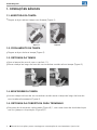
1. OPERAÇÕES BÁSICAS
1.1. ABERTURA DA TAMPA
g
Segure a alça e abra a tampa com firmeza (Figura 1).
1.2. FECHAMENTO DA TAMPA
g
Segure a alça e feche a tampa (Figura 2).
1.3. RETIRADA DA TAMPA
g
Abra a tampa (de acordo com o capítulo 1.1);
g
Mova a tampa ao longo da base da seccionadora e então retire a tampa (Figura 3).
1.4. MONTAGEM DA TAMPA
g
Insira a tampa na base da seccionadora e então mova a tampa ao longo da base da
seccionadora firmemente (Figura 4).
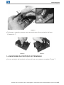
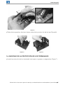
1.5. RETIRADA DA COBERTURA PARA TERMINAIS
g
Na proteção de terminais selecionada (Figura 5) 1, com uma chave de fenda desloque
um dos grampos da proteção (Figura 5) 2;
Figura 1
Figura 2
Figura 3 Figura 4

www.weg.net
Manual de instruções para a montagem e manutenção de seccionadoras tipo fusível 5
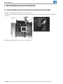
g
Desloque o segundo grampo e ao mesmo tempo retire a proteção da base
(Figuras 6 e 7).
Figura 5
1.6. MONTAGEM DA PROTEÇÃO DE TERMINAIS
g
Insira a proteção de terminais na base até que seus grampos engatem (Figura 7).
2
2
1
Figura 6 Figura 7
1
2
1

www.weg.net
Manual de instruções para a montagem e manutenção de seccionadoras tipo fusível6
g
Monte a tampa (de acordo com o capítulo 1.4).
Figura 8
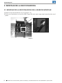
2. MONTAGEM DA SECCIONADORA
2.1. MONTAGEM DA SECCIONADORA NA BASE DE MONTAGEM
g
Retire a tampa (de acordo com o capítulo 1.3);
g
Fixe a seccionadora com parafusos M6 (Figura 8) até que se tenha uma boa fixação no
painel;

www.weg.net
Manual de instruções para a montagem e manutenção de seccionadoras tipo fusível 7
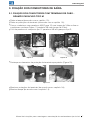
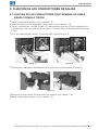
3. FIXAÇÃO DOS CONDUTORES DE SAÍDA
3.1. FIXAÇÃO DOS CONDUTORES COM TERMINAIS DE CABO -
GRAMPO PARAFUSO TIPO M
g
Retire a tampa (de acordo com o capítulo 1.3);
g
Retire as proteções de terminais (de acordo com o capítulo 1.5);
g
Fixe os condutores com parafusos M5 (Figura 12) com torque de 3 Nm ou fixe os
condutores conforme Figura 11 (parafuso M6 com torque de 3 Nm);
g
O kit de parafusos é composto por 12 parafusos M5 e 6 grampos tipo S;
Figura 12
Figura 11
g
Monte as proteções de terminais (de acordo com o capítulo 1.6);
g
Monte a tampa (de acordo com o capítulo 1.4).
g
Destaque os elementos da proteção de terminais apropriados (Figura 13);
Figura 13
1 2

www.weg.net
Manual de instruções para a montagem e manutenção de seccionadoras tipo fusível8
g
Mova um elo-fusível ao longo da tampa até a trava de elos-fusíveis prender (Figura 18);
g
Monte a tampa (de acordo com o capítulo 1.4).
4. INSERÇÃO, RETIRADA E VERIFICAÇÃO DE ELOS-
FUSÍVEIS
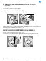
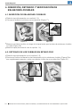
4.1. INSERÇÃO DE ELOS-FUSÍVEIS
g
Retire a tampa (de acordo com o capítulo 1.3);
g
Coloque o elo-fusível em um porta-fusível (Figura 17);
4.2. RETIRADA DOS FUSÍVEIS (TEMPERATURA AMBIENTE)
g
Retire a tampa (de acordo com o capítulo 1.3);
g
Pressione o botão de liberação de travamento dos elos-fusíveis (Figura 19) e em
seguida puxe e retire um elo-fusível de um porta-fusível (Figura 20).
Figura 17 Figura 18
Figura 19 Figura 20

www.weg.net
Manual de instruções para a montagem e manutenção de seccionadoras tipo fusível 9
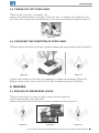
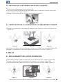
4.4. VERIFICAÇÃO DE CONDIÇÃO DOS ELOS-FUSÍVEIS
g
Mova a corrediça da tampa para a direita para liberar os orifícios de inspeção (Figura 22);
5. LACRE
5.1. TRAVAMENTO DE ORIFÍCIOS DE MEDIÇÃO
g
Para travar mova a corrediça da tampa para a posição superior (Figura 25);
g
Insira o dispositivo de travamento de acordo com a Figura 26;
g
Para destravar mova a corrediça da tampa até a posição central (Figura 27).
Figura 22 Figura 23 Figura 24
g
Verifique a condição dos elos-fusíveis com um detector de tensão (Figura 23);
g
Mova a corrediça da tampa até a posição central (Figura 24).
Figura 25 Figura 26 Figura 27
Figura 21
4.3. RETIRADA DOS FUSÍVEIS (AQUECIDO)
g
Retire a tampa (de acordo com o capítulo 1.3);
g
Pressione o botão de liberação de travamento dos elos-fusíveis (de acordo com o
capítulo 4.2.) (Figura 19, 20);
g
Balance a tampa até desconectar os fusíveis (Figura 21).

www.weg.net
Manual de instruções para a montagem e manutenção de seccionadoras tipo fusível10
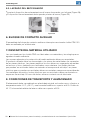
5.2. LACRE DA SECCIONADORA
g
Insira o dispositivo de travamento no orifício de acordo com a Figura 28;
g
O dispositivo de travamento deve ficar próximo ao orifício (Figura 29).
Figura 28
Figura 29
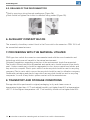
6. CONTATOS AUXILIARES
A montagem da chave de contato auxiliar na seccionadora tipo fusível FSW 100 deve ser
realizado pelo fabricante. Não é recomendada a montagem pelo usuário.
7. DESCARTE DO MATERIAL UTILIZADO
As seccionadoras tipo fusível FSW são fabricadas com materiais e tecnologia que não
agridem o meio ambiente.
Normas referentes à proteção do meio ambiente devem ser respeitadas.
O produto utilizado deve ser desmontado e as peças de metal devem ser separadas
das peças plásticas. Peças metálicas sem uso devem ser segregadas em metais não
ferrosos e outros e devem ser sucateadas. Peças plásticas que podem ser recicladas
devem ser enviadas para empresa de reciclagem. Peças plásticas que não podem ser
recicladas devem ser enviadas para empresa especializadas. Embalagens de papelão e
sacos plásticos que são reciclados devem ser enviados para empresas de reciclagem.
Em caso de dúvidas, entre em contato com o fabricante.
8. CONDIÇÕES DE TRANSPORTE E ARMAZENAMENTO
O armazenamento deve ser realizado na embalagem original, em locais secos e limpos
em temperatura superior a -5 ºC e umidade relativa não superior a 80% a temperatura
de +35 ºC. A temperatura mais alta de 40 ºC, a umidade relativa do ar não deve ser
superior a 50%.

www.weg.net
Instruction manual for mounting and service of fuse switch disconnectors 11
CONTENT
ENGLISH
1. BASIC OPERATIONS ............................................................................... 12
1.1. OPENNING OF THE COVER ............................................................ 12
1.2. CLOSING THE COVER ..................................................................... 12
1.3. TAKING OFF THE COVER ................................................................ 12
1.4. MOUNTING THE COVER ................................................................. 12
1.5. TAKING OFF THE SHIELD FOR TERMINALS ................................ 12
1.6. MOUNTING THE SHIELD FOR TERMINALS .................................. 13
2. MOUNTING THE DISCONNECTOR ........................................................14
2.1. MOUNTING THE DISCONNECTOR ON A MOUNTING PLATE ......14
3. FIXING OUTGOING CONDUCTORS ...................................................... 15
3.1. FIXING CONDUCTORS WITH CABLE TERMINAL- BOLT CLAMP
OF M TYPE ....................................................................................... 15
4. INSERTING, TAKING OFF AND CHECKING OF FUSE LINKS .............. 16
4.1. MOUNTING OF FUSE LINKS ........................................................... 16
4.2. TAKING OFF COLD FUSE LINKS .................................................... 16
4.3. TAKING OFF HOT FUSE LINKS .......................................................17
4.4. CHECKING THE CONDITION OF FUSE LINKS ..............................17
5. SEALING ....................................................................................................17
5.1. SEALING OF MEASURING HOLES ..................................................17
5.2. SEALING OF THE DISCONNECTOR .............................................. 18
6. AUXILIARY CONTACT BLOCK ................................................................ 18
7. PROCEEDING WITH THE MATERIAL UTILIZED ................................... 18
8. TRANSPORT AND STORAGE CONDITIONS ......................................... 18

www.weg.net
Instruction manual for mounting and service of fuse switch disconnectors12
1. BASIC OPERATIONS
1.1. OPENNING OF THE COVER
g
Take the handle and open the cover up to firm resistance (Figure 1).
1.2. CLOSING THE COVER
g
Take the handle and close the cover (Figure 2).
1.3. TAKING OFF THE COVER
g
Open the cover (acc. to chapter 1.1);
g
Move the cover along the base of the disconnector and then take off the cover form the
base (Figure 3).
1.4. MOUNTING THE COVER
g
Insert the cover into the disconnector base and then move the cover along the
disconncetor base up to firm resistance (Figure 4).
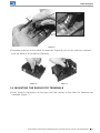
1.5. TAKING OFF THE SHIELD FOR TERMINALS
g
Using a screwdriver press locking of catches of the shield and simultaneously squeeze
catches of the shield for terminals making them released (Figure 5);
Figure 1
Figure 2
Figure 3 Figure 4

www.weg.net
Instruction manual for mounting and service of fuse switch disconnectors 13
g
Squeezing catches of the shield for terminals (Figure 6) pull out the shield for terminals
form the base of disconnector (Figure 6).
Figure 5
1.6. MOUNTING THE SHIELD FOR TERMINALS
g
Insert shield for terminals into the base until the catches of the shield for terminals are
slammed (Figure 7).
2
2
Figure 6 Figure 7
1
2
1
1

www.weg.net
Instruction manual for mounting and service of fuse switch disconnectors14
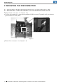
2. MOUNTING THE DISCONNECTOR
2.1. MOUNTING THE DISCONNECTOR ON A MOUNTING PLATE
g
Take off the cover (acc. to chapter 1.3);
g
Fix the disconnector to a mounting plate with M6 screws (Figure 8) until you have a
good fixation on the panel;
g
Mount the cover (acc. to chapter 1.4).
Figure 8

www.weg.net
Instruction manual for mounting and service of fuse switch disconnectors 15
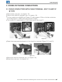
3. FIXING OUTGOING CONDUCTORS
3.1. FIXING CONDUCTORS WITH CABLE TERMINAL- BOLT CLAMP OF
M TYPE
g
Take off the cover (acc. to chapter 1.3);
g
Take off the shield for terminals (acc. to chapter 1.5);
g
Fix the conductors with M5 bolt (Figure 12) with torque of 3 Nm or fix the conductors
according Figure 11 (M6 screw with torque of 3 Nm);
g
The screw kit is compound by 12 M5 screw and 6 clips type S;
Figure 12
Figure 11
g
Mount the shield for terminals (acc. to chapter 1.6);
g
Mount the cover (acc. to chapter 1.4).
g
Break down appropriate elements of the shield for terminals (Figure 13 (1 and 2));
Figure 13
1 2

www.weg.net
Instruction manual for mounting and service of fuse switch disconnectors16
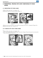
g
Move a fuse link along the cover until the locking of fuse links is slammed (Figure 18);
g
Mount the cover ( acc. to point 1.4).
4. INSERTING, TAKING OFF AND CHECKING OF FUSE
LINKS
4.1. MOUNTING OF FUSE LINKS
g
Take off the cover (acc. to chapter 1.3);
g
Place the fuse link in a fuse holder (Figure 17);
4.2. TAKING OFF COLD FUSE LINKS
g
Take off the cover (acc. to chapter 1.3);
g
Press the release button for locking of fuse links (Figure 19) and then pull out a fuse link
from a fuse holder (Figure 20).
Figure 17 Figure 18
Figure 19 Figure 20

www.weg.net
Instruction manual for mounting and service of fuse switch disconnectors 17
Figure 21
4.3. TAKING OFF HOT FUSE LINKS
g
Take off the cover (acc. to chapter 1.3);
g
Press the release button for locking of fuse links (acc. to chapter 4.2.) (Figure 19, 20);
g
Tilt the cover causing the self pulling out of fuse links from the fuse holders (Figure 21).
4.4. CHECKING THE CONDITION OF FUSE LINKS
g
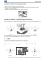
Move a slide of the cover to the right in order to make clear the inspection holes (Figure 22);
5. SEALING
5.1. SEALING OF MEASURING HOLES
g
Move up the slide of a cover in order to seal a cover (Figure 25);
g
Pull a seal through a lug (Figure 26);
g
Move down the slide of the cover in order to release the slide (Figure 27).
g
Check the condition of fuse links for example by voltage measurement (Figure 23);
g
Move a slide of the cover to the left until it gets the neutral position (Figure 24).
Figure 22 Figure 23 Figure 24
Figure 25 Figure 26 Figure 27

www.weg.net
Instruction manual for mounting and service of fuse switch disconnectors18
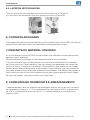
6. AUXILIARY CONTACT BLOCK
The assembly of auxiliary contact block in the Fuse switch-disconnectors FSW 100 it will
be assembled manufacturers.
7. PROCEEDING WITH THE MATERIAL UTILIZED
FSW type fuse switch disconnectors are manufactured with the use of materials and
technology which are not harmful to the natural environment.
Obligatory regulations regarding protection of the environment should be respected.
The product utilized should be dismantled and metal parts should be apart from plastic
ones. Useless metal parts should be segregated to non- ferrous metals and others and
they are to be scraped. Plastic parts which can be recycled should be sent to recycling
company. Plastic parts which can not be recycled should be sent to utilization company.
Cardboard packaging and plastic bags which are recycled should be sent to recycling
companies. In case of any doubts please contact with the manufacturer.
8. TRANSPORT AND STORAGE CONDITIONS
Storage should be performed in original packaging, in dry and clean rooms at
temperature higher than -5
o
C and related humidity not higher than 80% at temperature
+35
o
C. At the highest temperature +40
o
C air humidity should not be higher than 50%.
5.2. SEALING OF THE DISCONNECTOR
g
Seal by passing a string through sealing eye (Figure 28);
g
Seal should be tighten the closest to element being sealed (Figure 29).
Figure 28
Figure 29

www.weg.net
Manual de instrucciones para el montaje y mantenimiento de seccionadoras tipo fusible 19
CONTENIDO
ESPAÑOL
1. OPERACIONES BÁSICAS ........................................................................ 20
1.1. APERTURA DE LA TAPA .................................................................. 20
1.2. CIERRE DE LA PROTECCIÓN ........................................................ 20
1.3. REMOCIÓN DE LA PROTECCIÓN .................................................. 20
1.4. MONTAJE DE LA TAPA .................................................................... 20
1.5. REMOCIÓN DE LA COBERTURA PARA TERMINALES ............... 20
1.6. MONTAJE DE LA PROTECCIÓN DE LOS TERMINALES .............. 21
2. MONTAJE DE LA SECCIONADORA ...................................................... 22
2.1. MONTAJE DE LA SECCIONADORA EN LA BASE DE MONTAJE .. 22
3. FIJACIÓN DE LOS CONDUCTORES DE SALIDA ................................. 23
3.1. FIJACIÓN DE LOS CONDUCTORES CON TERMINAL DE
CABLE - GRAPA TORNILLO TIPO M .............................................. 23
4. INSERCIÓN, RETIRADO Y VERIFICACIÓN DE ESLABONES-
FUSIBLES .................................................................................................. 24
4.1. INSERCIÓN DE ESLABONES-FUSIBLES ...................................... 24
4.2. RETIRADO DE LOS FUSIBLES EN ESTADO FRIO ........................ 24
4.3. RETIRADO DE LOS FUSIBLES EN ESTADO CALIENTE .............. 25
4.4. VERIFICACIÓN DE LA CONDICIÓN DE LOS ESLABONES-
FUSIBLES .......................................................................................... 25
5. SELLO ........................................................................................................ 25
5.1. ENCLAVAMIENTO DEL HUECO DE MEDICIÓN ............................ 25
5.2. LACRADO DEL SECCIONADOR .................................................... 26
6. BLOQUE DE CONTACTO AUXILIAR ....................................................... 26
7. DESCARTE DEL MATERIAL UTILIZADO................................................ 26
8. CONDICIONES DE TRANSPORTE Y ALMACENADO ........................... 26

www.weg.net
Manual de instrucciones para el montaje y mantenimiento de seccionadoras tipo fusible
20
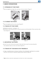
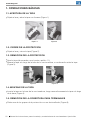
1. OPERACIONES BÁSICAS
1.1. APERTURA DE LA TAPA
g
Sujete el asa y abra la tapa con firmeza (Figura 1).
1.2. CIERRE DE LA PROTECCIÓN
g
Sujete el asa y cierre la tapa (Figura 2).
1.3. REMOCIÓN DE LA PROTECCIÓN
g
Abra la tapa (de acuerdo con el punto capítulo 1.1);
g
Mueva la tapa a lo largo de la base de la seccionadora, a continuación retire la tapa
(Figura 3).
1.4. MONTAJE DE LA TAPA
g
Inserte la tapa en la base de la seccionadora, luego mueva firmemente la tapa a lo largo
de la base (Figura 4).
1.5. REMOCIÓN DE LA COBERTURA PARA TERMINALES
g
Retire una de las grapas de la protección con un destornillador (Figura 5);
Figura 1
Figura 2
Figura 3 Figura 4
A página está carregando...
A página está carregando...
A página está carregando...
A página está carregando...
A página está carregando...
A página está carregando...
A página está carregando...
A página está carregando...
-
 1
1
-
 2
2
-
 3
3
-
 4
4
-
 5
5
-
 6
6
-
 7
7
-
 8
8
-
 9
9
-
 10
10
-
 11
11
-
 12
12
-
 13
13
-
 14
14
-
 15
15
-
 16
16
-
 17
17
-
 18
18
-
 19
19
-
 20
20
-
 21
21
-
 22
22
-
 23
23
-
 24
24
-
 25
25
-
 26
26
-
 27
27
-
 28
28


em outras línguas
- español: WEG FSW 100 Manual de usuario
Artigos relacionados
-
WEG FSW 250 Manual do usuário
-
-
-
-
-
 Automation Direct SSW-07 Soft Manual do usuário
-
-
-
-
 Automation Direct CFW300 Manual do usuário

