Automation Direct CFW300 Manual do usuário
- Tipo
- Manual do usuário

Frequency Inverter
Convertidor de Frecuencia
Inversor de Frequência
CFW300
Motors | Automation | Energy | Transmission & Distribution | Coatings
User's Manual
Manual del Usuario
Manual do Usuário


User’s Manual
Series: CFW300
Language: English
Document: 10003325037 / 04
Models: Frame Sizes A, B and C
Publishing Date: 09/2019

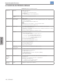
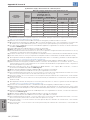
Summary of Reviews
English
The information below describes the reviews made to this manual.
Version Review Description
- R00 First edition
- R01 General revision
- R02 Launch of the 400 V line (T4 models, 380-480 V power supply)
- R03 General revision
- R04 Change of Figure B2 on page 143
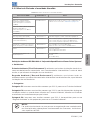
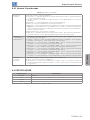
ATTENTION!
Check the frequency of the power supply.
In case the power supply frequency is different from the factory setting (check
P403), it is necessary to set:
P204 = 5 for 60 Hz.
P204 = 6 for 50 Hz.
It is only necessary to set these parameters once.
Refer to the programming manual of the CFW300 for further details about the
programming of parameter P204.

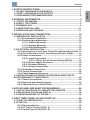
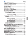
Contents
English
1 SAFETY INSTRUCTIONS .................................................................... 1
1.1 SAFETY WARNINGS IN THE MANUAL ....................................................1
1.2 SAFETY WARNINGS IN THE PRODUCT .................................................1
1.3 PRELIMINARY RECOMMENDATIONS ....................................................2
2 GENERAL INFORMATION ..................................................................4
2.1 ABOUT THE MANUAL ..............................................................................4
2.2 ABOUT THE CFW300 ................................................................................ 4
2.3 TERMINOLOGY .........................................................................................9
2.4 IDENTIFICATION LABEL .......................................................................11
2.5 RECEIVING AND STORAGE ...................................................................11
3 INSTALLATION AND CONNECTION ................................................12
3.1 MECHANICAL INSTALLATION ...............................................................12
3.1.1 Environmental Conditions ............................................................12
3.1.2 Positioning and Mounting.............................................................12
3.1.2.1 Cabinet Mounting ..............................................................13
3.1.2.2 Surface Mounting .............................................................13
3.1.2.3 DIN-Rail Mounting ............................................................. 13
3.2 ELECTRICAL INSTALLATION ................................................................13
3.2.1 Identification of the Power Terminals and Grounding Points .14
3.2.2 Circuit Breakers, Fuses, Grounding and Power Cables ..........14
3.2.3 Power Connections .......................................................................15
3.2.3.1 Input Connections .............................................................17
3.2.3.1.1 Short Circuit Current Ratings (SCCR) ............. 18
3.2.3.2 Power Supply Reactance ................................................18
3.2.3.3 Dynamic Braking ...............................................................19
3.2.3.4 Output Connections .........................................................20
3.2.4 Grounding Connections ...............................................................21
3.2.5 Control Connections ....................................................................22
3.2.6 Cable Separation Distance ..........................................................23
3.3 INSTALLATIONS ACCORDING TO EUROPEAN DIRECTIVE OF
ELECTROMAGNETIC COMPATIBILITY .....................................................23
3.3.1 Control Connections .....................................................................23
3.3.2 Emission and Immunity Levels ....................................................24
3.3.3 Characteristics of the RFI Filter .................................................25
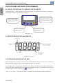
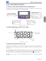
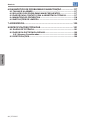
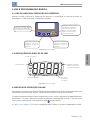
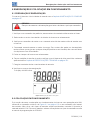
4 KEYPAD (HMI) AND BASIC PROGRAMMING ................................26
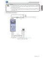
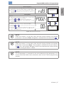
4.1 USE OF THE KEYPAD TO OPERATE THE INVERTER .........................26
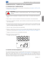
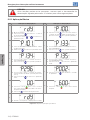
4.2 INDICATIONS ON THE HMI DISPLAY ...................................................26
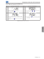
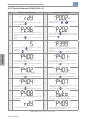
4.3 OPERATING MODES OF THE HMI ........................................................26
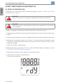
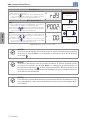
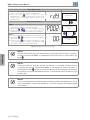
5 FIRST TIME POWER-UP AND START-UP .......................................28
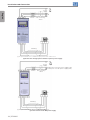
5.1 START-UP PREPARATION ......................................................................28
5.2 START-UP ................................................................................................29
5.2.1 Basic Application...........................................................................30
5.2.2 V/f Type of Control (P202 = 0) ......................................................31
5.2.3 Control Type VVW (P202 = 5).......................................................32

Contents
English
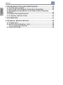
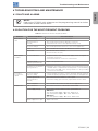
6 TROUBLESHOOTING AND MAINTENANCE ...................................33
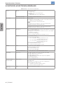
6.1 FAULTS AND ALARMS ............................................................................33
6.2 SOLUTION FOR THE MOST FREQUENT PROBLEMS ........................33
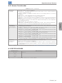
6.3 INFORMATION NECESSARY FOR CONTACTING TECHNICAL
SUPPORT .......................................................................................................34
6.4 PREVENTIVE MAINTENANCE................................................................34
6.5 CLEANING INSTRUCTIONS ..................................................................35
7 ACCESSORIES ..................................................................................37
8 TECHNICAL SPECIFICATIONS ........................................................38
8.1 POWER DATA ...........................................................................................38
8.2 ELECTRONICS/GENERAL DATA ...........................................................39
8.2.1 Considered Standards ..................................................................40
8.3 CERTIFICATIONS ....................................................................................40

CFW300 | 1
English
Safety Instructions
1 SAFETY INSTRUCTIONS
This manual provides information for the proper installation and operation of the CFW300
frequency inverter.
It has been written to be used by qualified personnel with suitable training or technical
qualification for operating this type of equipment. The personnel must follow all the safety
instructions described in this manual and/or defined by the local regulations. Failure to comply
with the safety instructions may result in death, serious injury, and equipment damage.
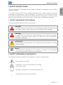
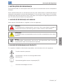
1.1 SAFETY WARNINGS IN THE MANUAL
The following safety notices are used in the manual:
DANGER!
The procedures recommended in this warning have the purpose of protecting the
user against death, serious injuries and considerable material damage.
DANGER!
Les procédures concernées par cet avertissement sont destinées à protéger
l'utilisateur contre des dangers mortels, des blessures et des détériorations
matérielles importantes.
ATTENTION!
The procedures recommended in this warning have the purpose of avoiding
material damage.
NOTE!
The information mentioned in this warning is important for the proper
understanding and good operation of the product.
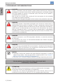
1.2 SAFETY WARNINGS IN THE PRODUCT
The following symbols are attached to the product, serving as safety notices:
High voltages are present.
Components sensitive to electrostatic discharge.
Do not touch them.
Mandatory connection to the protective ground (PE).
Connection of the shield to the ground.

2 | CFW300
English
Safety Instructions
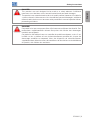
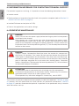
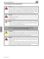
1.3 PRELIMINARY RECOMMENDATIONS
DANGER!
Always disconnect the main power supply before touching any electrical
component associated to the inverter. Several components can remain charged
with high voltages or remain in movement (fans) even after the AC power is
disconnected or switched off.
Wait at least ten minutes after turning off the input power for the complete
discharge of the power capacitors.
Always connect the grounding point of the inverter to the protection earth (PE).
DANGER!
Débranchez toujours l'alimentation principale avant d'entrer en contact avec un
appareil électrique associé au variateur. Plusieurs composants peuvent rester
chargés à un potentiel électrique élevé et/ou être en mouvement (ventilateurs),
même après la déconnexion ou la coupure de l'alimentation en courant
alternatif. Attendez au moins 10 minutes que les condensateurs se déchargent
complètement. Toujours connecter le point de mise à la terre du variateur sur la
mise à la terre de protection.
DANGER!
The XC10 connector is not USB compatible, therefore, it cannot be connected
to USB ports.
This connector only serves as the interface between the CFW300 frequency
inverter and its accessories.
DANGER!
La XC10 n'est pas compatible USB, par conséquent, il ne peut pas être connectés
à des ports USB. Ce connecteur sert uniquement d'interface entre le CFW300
variateur de fréquence et de ses accessoires.
NOTES!
Frequency Inverter may interfere with other electronic equipment. In order to
reduce these effects, take the precautions recommended in the Chapter 3
INSTALLATION AND CONNECTION on page 12.
Read the user's manual completely before installing or operating the inverter.
Do not perform any withstand voltage test (hi-pot test)!
If necessary, contact WEG.
ATTENTION!
Electronic boards have components sensitive to electrostatic discharges.
Do not touch directly on components or connectors.
If necessary, first touch the grounding point of the inverter, which must be
connected to the protection earth (PE) or use a proper grounding strap.

CFW300 | 3
English
Safety Instructions
DANGER!
This product was not designed to be used as a safety element. Additional
measures must be taken so as to avoid material and personal damages.
The product was manufactured under strict quality control, however, if installed in
systems where its failure causes risks of material or personal damages, additional
external safety devices must ensure a safety condition in case of a product failure,
preventing accidents.
DANGER!
Ce produit n'est pas conçu pour être utilisé comme un élément de sécurité. Des
précautions supplémentaires doivent être prises afin d'éviter des dommages
matériels ou corporels.
Ce produit a été fabriqué sous un contrôle de qualité conséquent, mais s'il est
installé sur des systèmes où son dysfonctionnement entraîne des risques de
dommages matériels ou corporels, alors des dispositifs de sécurité externes
supplémentaires doivent assurer des conditions de sécurité en cas de défaillance
du produit, afin d'éviter des accidents.

4 | CFW300
English
General Information
2 GENERAL INFORMATION
2.1 ABOUT THE MANUAL
This manual contains information for the proper installation and operation of the inverter,
commissioning, main technical features and how to identify the most usual problems of the
different models of inverters of the CFW300 line.
ATTENTION!
The operation of this equipment requires detailed installation and operation
instructions provided in the quick installation guide, user's manual, programming
manual and communication manuals. The guides are provided in print with their
respective accessory, or can be obtained at WEG website - www.weg.net. A
printed copy of the files can be requested at your local WEG dealer.
NOTE!
It is not the intention of this manual to present all the possibilities for the application
of the CFW300, as well as WEG cannot take any liability for the use of the CFW300
which is not based on this manual.
Part of the figures and tables are available in the annexes, which are divided into APPENDIX
A - FIGURES on page 124 for figures and APPENDIX B - TECHNICAL SPECIFICATIONS on
page 128 for technical specifications.
For further information, refer to the programming manual.
2.2 ABOUT THE CFW300
The CFW300 frequency inverter is a high-performance product which allows speed and torque
control of three-phase induction motors. This product provides the user with the options of
vector (VVW) or scalar (V/f) control, both programmable according to the application.
In the vector mode (VVW), the operation is optimized for the motor in use, obtaining a better
performance in terms of speed regulation.
The scalar mode (V/f) is recommended for simpler applications, such as the activation of most
pumps and fans. In such cases it is possible to reduce the losses in the motor and the inverter
using the "V/f Quadratic", which results in energy savings. The V/f mode is used when more
than a motor is activated by an inverter simultaneously (multimotor applications).
The frequency inverter CFW300 also has functions of PLC (Programmable Logic Controller) by
means of the SoftPLC (integrated) feature.
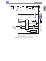
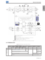
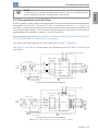
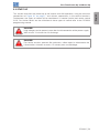
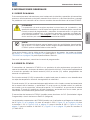
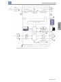
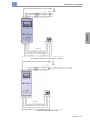
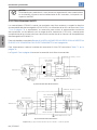
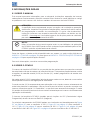
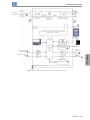
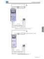
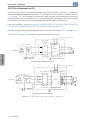
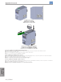
The main components of the CFW300 can be viewed in the blocks diagrams of Figure 2.1 on
page 5, for frame size A 220 V, Figure 2.2 on page 6 for frame size A 110 V, Figure 2.3
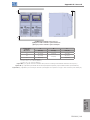
on page 7 for frame size B 220 V, Figure 2.4 on page 8 for frame size A 380-480 V and
Figure 2.5 on page 9 for frame sizes B and C 380-480 V.

CFW300 | 5
English
General Information
Digital inputs
(DI1 to DI4)
Sources for electronics and interfaces between
power and control
Power
Single-phase /
three-phase
rectifier
Preload
Motor
3~
U/T1
V/T2
W/T3
Inverter
with IGBT
transistors
Power
supply
R/L1/L (-UD)
T/L3
RS-485
DC Link
capacitor
bank
HMI
Control
board
with
CPU
16 bits
Flash Memory
Module
Interfaces (RS-232,
RS-485, USB,
CANopen, DeviceNet,
Profibus DP, Bluetooth
or Ethernet)
Analog
output
(AO1)
HMI (remote)
PE
PE
Digital
output
DO1
(RL1)
Software
WPS
Control
PC
Analog input
(AI1)
S/L2/N (+UD)
Rsh
RFI Filter
1
1
2
3
3
3
3
3
4
4
4
4
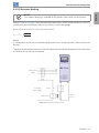
1
DC power supply connection available for specific models only.
2
Three-phase power supply connection available for specific models only.
3
Available as accessory.
4
Number of Inputs/Outputs depends on the I/O expansion accessory used.
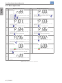
Figure 2.1: Block diagram of CFW300 for frame size A 220 V

6 | CFW300
English
General Information
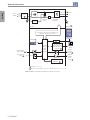
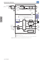
Digital inputs
(DI1 to DI4)
Sources for electronics and interfaces
between power and control
Power
Single-phase
Preload
Motor
3~
U/T1
V/T2
W/T3
Inverter
with IGBT
transistors
L1/L
RS-485
DC Link
capacitor
bank
HMI
Control
board
with
CPU
16 bits
Interfaces (RS-232,
RS-485, USB,
CANopen, DeviceNet,
Profibus DP, Bluetooth
or Ethernet)
Analog
output
(AO1)
HMI (remote)
PE
PE
Digital
output
DO1
(RL1)
Software
WPS
Control
Analog input
(AI1)
L2/N
Rsh
1
1
1
Flash Memory
Module
1
2
2
2
2
PC
RFI
Filter
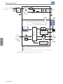
1
Power
supply
1
Available as accessory.
2
Number of Inputs/Outputs depends on the I/O expansion accessory used.
Figure 2.2: Block diagram of CFW300 for frame size A 110 V

CFW300 | 7
English
General Information
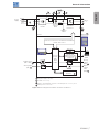
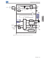
Braking
IGBT
Digital inputs
(DI1 to DI4)
Sources for electronics and interfaces between
power and control
Power
Three-phase
rectifier
Preload
Motor
3~
U/T1
V/T2
W/T3
Inverter
with IGBT
transistors
Power
supply
R/L1/L
T/L3
RS-485
DC Link
capacitor
bank
HMI
Control
board
with
CPU
16 bits
Flash Memory
Module
Interfaces (RS-232,
RS-485, USB,
CANopen, DeviceNet,
Profibus DP, Bluetooth
or Ethernet)
Analog
output
(AO1)
HMI (remote)
PE
PE
Digital
output
DO1
(RL1)
Software
WPS
Control
Analog input
(AI1)
S/L2/N
Rsh
+UD -UD +BR BR
RFI Filter
2
1 1
4 4
2
2
2
2
3
3
3
3
PC
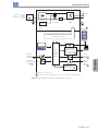
1
DC power supply connection.
2
Available as accessory.
3
Number of Inputs/Outputs depends on the I/O expansion accessory used.
4
Braking resistor connection.
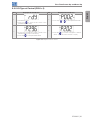
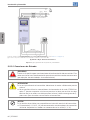
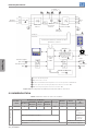
Figure 2.3: Block diagram of CFW300 for frame size B 220 V

8 | CFW300
English
General Information
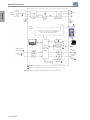
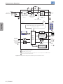
Digital inputs
(DI1 to DI4)
2
Sources for electronics and interfaces
between power and control
Power
Three-phase
rectifier
Inverter with
IGBT transistors
DC Link
capacitor
bank
Preload Rsh
Motor
3~
Power
supply
R/L1 U/T1
T/L3
W/T3
RS-485
HMI
Control
board
with CPU
16 bits
Flash Memory
Module
Interfaces (RS-232,
RS-485, USB,
CANopen, DeviceNet,
Profibus DP, Bluetooth
or Ethernet)
Analog
output
(AO1)
HMI (remote)
PE
PE
Digital
output
DO1
(RL1)
Software
WPS
Control
Analog input
(AI1)
2
S/L2
V/T2
RFI Filter
1
1
2
2
PC
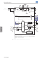
1
1
1
1
Available as accessory.
2
Number of Inputs/Outputs depends on the I/O expansion accessory used.
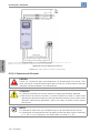
Figure 2.4: Block diagram of CFW300 for frame size A 380-480 V

CFW300 | 9
English
General Information
Digital inputs
(DI1 to DI4)
3
Sources for electronics and interfaces
between power and control
Power
Three-phase
rectifier
-UD +UD +BR BR
Inverter with
IGBT transistors
Braking
IGBT
DC Link
capacitor
bank
Preload Rsh
Motor
3~
Power
supply
R/L1
U/T1
T/L3
W/T3
RS-485
2
HMI
Control
board
with CPU
16 bits
Flash Memory
Module
2
Interfaces (RS-232,
RS-485, USB,
CANopen, DeviceNet,
Profibus DP, Bluetooth
or Ethernet)
2
Analog output
(AO1)
3
HMI (remote)
PE
PE
Digital output
DO1 (RL1)
3
Software WPS
Control
Analog input
(AI1)
3
S/L2
V/T2
RFI Filter
PC
2
2
1 1 4 4
5
1
DC power supply connection.
2
Available as accessory.
3
Number of Inputs/Outputs depends on the I/O expansion accessory used.
4
Braking resistor connection (available only on 'DB' models).
5
Braking IGBT available only on 'DB' models.
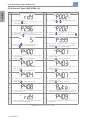
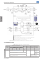
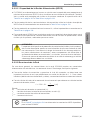
Figure 2.5: Block diagram of CFW300 for frame sizes B and C 380-480 V
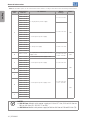
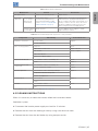
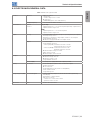
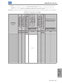
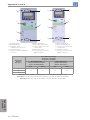
2.3 TERMINOLOGY
Table 2 .1: Terminology of the CFW300 inverters
Product
and Series
Model Identification
Brake
Degree of
Protection
Hardware
Version
Software
Version
Frame
Size
Rated
Current
Phase
Number
Rated
Voltage
E.g.: CFW300 A 01P6 S 2 NB 20 --- ---
Available options
CFW300
Refer to Table 2.2 on page 10
Blank =
standard
NB = without dynamic braking Sx = special
software
DB = with dynamic braking Blank = standard
20 = IP20 Hx = special hardware

10 | CFW300
English
General Information
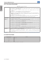
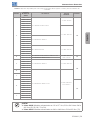
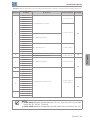
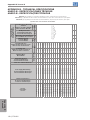
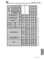
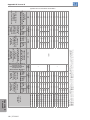
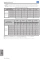
Table 2 .2: Available options for each field of the nomenclature according to the rated current and voltage of the inverter
Frame
Size
Output Rated
Current
N° of Phases
Rated
Voltage
Brake
A
01P6 = 1.6 A
S = single-phase power supply
1 = 110...127 Vac
NB
02P6 = 2.6 A
04P2 = 4.2 A
06P0 = 6.0 A
01P6 = 1.6 A
2 = 200...240 Vac
02P6 = 2.6 A
04P2 = 4.2 A
06P0 = 6.0 A
07P3 = 7.3 A
01P6 = 1.6 A
T = three-phase power supply
02P6 = 2.6 A
04P2 = 4.2 A
06P0 = 6.0 A
07P3 = 7.3 A
01P6 = 1.6 A
D = DC power supply 3 = 280...340 Vdc
02P6 = 2.6 A
04P2 = 4.2 A
06P0 = 6.0 A
07P3 = 7.3 A
B
10P0 = 10.0 A
B = single-phase or three-phase power
supply or DC
2 = 200...240 Vac
or 280...340 Vdc
DB
15P2 = 15.2 A T = three-phase power supply or DC
A
01P1 = 1.1 A
T = three-phase power supply 4 = 380...480 Vac
NB
01P8 = 1.8 A
02P6 = 2.6 A
03P5 = 3.5 A
04P8 = 4.8 A
B
06P5 = 6.5 A
T = three-phase power supply or DC
4 = 380...480 Vac
or 513...650 Vdc
08P2 = 8.2 A
C
10P0 = 10.0 A
12P0 = 12.0 A
15P0 = 15.0 A
B
01P1 = 1.1 A
DB
01P8 = 1.8 A
02P6 = 2.6 A
03P5 = 3.5 A
04P8 = 4.8 A
06P5 = 6.5 A
08P2 = 8.2 A
C
10P0 = 10.0 A
12P0 = 12.0 A
15P0 = 15.0 A
NOTE!
200 V Line: Models with power supply of 110 to 127 Vac, 200 to 240 Vac or
280 to 340 Vdc (S1, S2, B2, T2 or D3).
400 V Line: Models with power supply of 380 to 480 Vac or 513 to 650 Vdc (T4).

CFW300 | 11
English
General Information
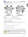
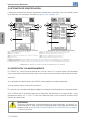
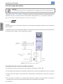
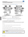
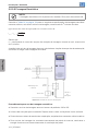
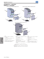
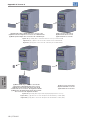
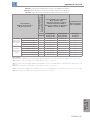
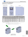
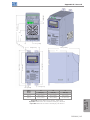
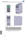
2.4 IDENTIFICATION LABEL
The identification label is located on the side of the inverter. For further details on positioning
the label, refer to Figure A2 on page 125.
1
6
8
73
4
5
2
1
6
8
11
12
73
4
9
10
5
2
(b) Side label of the CFW300 - 400 V Line(a) Side label of the CFW300 - 200 V Line
(1) Model (Inverter intelligent code).
(2) WEG stock item.
(3) Production order.
(4) Rated input data (voltage, current and frequency).
(5) Certifications.
(6) Serial number.
(7) Manufacturing date (14 corresponds to the week and I to the year).
(8) Rated output data (voltage, current and frequency).
(9) Input current for voltage range 1
(**)
.
(10) Input current for voltage range 2
(**)
.
(11) Output current for voltage range 1
(**)
.
(12) Output current for voltage range 2
(**)
.
(*) Voltage Range 1: Rated currents specified for mains power supply voltages of 380-400-415 Vac (513-540-560 Vdc).
(**) Voltage Range 2: Rated currents specified for mains power supply voltages of 440-460-480 Vac (594-621-650 Vdc).
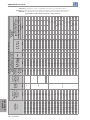
For further details, refer to Table B1 on page 128 and Table B4 on page 135, and also to the CFW300 programming manual.
Figure 2.6: (a) and (b) Description of the CFW300 identification label
2.5 RECEIVING AND STORAGE
The CFW300 is supplied packed in a cardboard box. There is an identification label affixed to
the outside of the package, identical to the one affixed to the side of the inverter.
Verify whether:
The CFW300 identification label corresponds to the purchased model.
Any damage occurred during transportation.
Report any damage immediately to the carrier.
If the CFW300 is not installed soon, store it in a clean and dry location (temperature between
-25 ºC and 60 ºC (-13 ºF and 140 ºF)), with a cover to prevent dust accumulation inside it.
ATTENTION!
When the inverter is stored for a long period, it becomes necessary to perform
the capacitor reforming. Refer to the procedure recommended in Section 6.4
PREVENTIVE MAINTENANCE on page 34 of this manual.

12 | CFW300
English
Installation and Connection
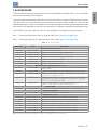
3 INSTALLATION AND CONNECTION
3.1 MECHANICAL INSTALLATION
3.1.1 Environmental Conditions
Avoid:
Direct exposure to sunlight, rain, high humidity or sea-air.
Inflammable or corrosive gases or liquids.
Excessive vibration.
Dust, metallic particles or oil mist.
Environment conditions permitted for the operation of the inverter:
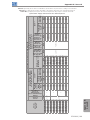
Temperature around the inverter: 0 ºC (32 ºF) up to the rated temperature indicated in Table
B4 on page 135:
- 200 V Line: from 0 ºC to 50 ºC (32 ºF to 122 ºF).
- 400 V Line: from 0 ºC to 40 ºC (32 ºF to 104 ºF).
For temperatures surrounding the inverter higher than the specifications above, it is necessary
to apply a 2 % of current derating for each degree Celsius (1.1 % for each degree Fahrenheit),
limited to an increase of 10 ºC (18 ºF).
Air relative humidity: 5 % to 95 % non-condensing.
Maximum altitude: up to 1000 m (3.300 ft) - rated conditions.
From 1000 m to 4000 m (3.300 ft to 13.200 ft) - 1 % of current derating for each 100 m
(330 ft) above 1000 m (3.300 ft) of altitude.
From 2000 m to 4000 m (6.600 ft to 13.200 ft) above sea level – maximum voltage derating
(127 V / 240 V / 480 V, according to the model, as indicated in Table B1 on page 128) of
1.1 % for each 100 m (330 ft) above 2000 m (6.600 ft).
Pollution degree: 2 (according to EN50178 and UL508C), with non-conductive pollution.
Condensation must not originate conduction through the accumulated residues.
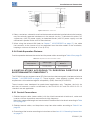
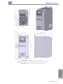
3.1.2 Positioning and Mounting
The external dimensions and fixing holes, likewise the inverter net weight (mass) are shown in
Figure B1 on page 141.
Mount the inverter in the upright position on a flat and vertical surface. Allow the minimum
clearances indicated in Figure B2 on page 143, in order to allow the circulation of the cooling
air. Do not install heat sensitive components right above the inverter.

CFW300 | 13
English
Installation and Connection
ATTENTION!
When installing two or more inverters vertically, respect the minimum clearance
A + B (as shown in Figure B2 on page 143) and provide an air deflecting plate
so that the heat rising up from the lower inverter does not affect the top inverter.
Provide independent conduits for the physical separation of signal, control and
power cables (refer to Section 3.2 ELECTRICAL INSTALLATION on page 13).
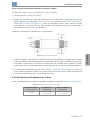
3.1.2.1 Cabinet Mounting
For inverters installed inside cabinets or metallic boxes, provide proper exhaustion, so that the
temperature remains within the allowed range. Refer to the dissipated powers in Table B4 on page 135.
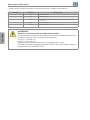
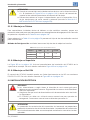
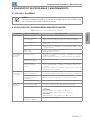
As a reference, Table 3.1 on page 13 shows the air flow of rated ventilation for each model.
Cooling Method: internal fan with air flow upwards.
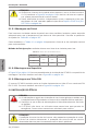
Table 3 .1: Air flow of the internal fan
Model CFM I/s m
3
/min
A
17. 0 8.02 0.48
B
C 40.4 19.09 1.15
3.1.2.2 Surface Mounting
Figure B2 on page 143 illustrates the CFW300 installation procedure for surface mounting.
3.1.2.3 DIN-Rail Mounting
The CFW300 inverter can also be mounted directly on a 35 mm-rail, in accordance with
DIN EN 50.022. For further details, refer to Figure B2 on page 143.
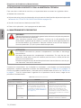
3.2 ELECTRICAL INSTALLATION
DANGER!
The following information is merely a guide for proper installation. Comply with
applicable local regulations for electrical installations.
Make sure the AC power supply is disconnected before starting the installation.
The CFW300 must not be used as an emergency stop device. Provide other
devices for that purpose.
DANGER!
Les informations suivantes constituent uniquement un guide pour une
installation correcte. Respectez les réglementations locales en vigueur pour
les installations électriques.
Vérifiez que l'alimentation secteur CA est débranchée avant de commencer
l'installation.
Le CFW300 ne devra pas être utilisé comme un dispositif d'arrêt d'urgence.
Utilisez des dispositifs additionnels appropriés dans ce but.
ATTENTION!
Integral solid state short circuit protection does not provide branch circuit
protection. Branch circuit protection must be provided in accordance with
applicable local codes.

14 | CFW300
English
Installation and Connection
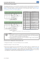
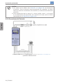
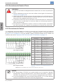
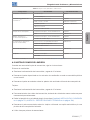
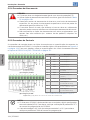
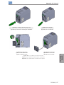
3.2.1 Identification of the Power Terminals and Grounding Points
The power terminals can be of different sizes and configurations, depending on the model of
the inverter, according to Figure B3 on page 144. The location of the power, grounding and
control connections are shown in Figure B3 on page 144.
Description of the power terminals:
L/L1, N/L2, L3 (R,S,T): power supply connection.
U, V and W: connection for the motor.
-UD: negative pole of the DC power supply.
+UD: positive pole of the DC power supply.
+BR, BR: connection of the braking resistor (available for DB models).
PE: grounding connection.
The maximum tightening torque of the power terminals and grounding points must be checked
in Figure B3 on page 144.
DANGER!
Observe the correct DC power supply connection, polarity and terminal positions.
DANGER!
Observer la bonne connexion de l'alimentation en courant continu, la polarité
et l'emplacement des bornes.
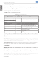
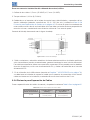
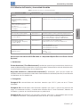
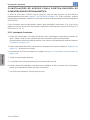
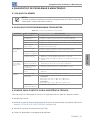
3.2.2 Circuit Breakers, Fuses, Grounding and Power Cables
ATTENTION!
Use proper cable lugs for the power and grounding connection cables. Refer to
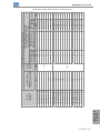
Table B1 on page 128 for recommended wiring, and Table B2 on page 130 and
Table B3 on page 133 for recommended circuit breakers and fuses.
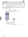
Keep sensitive equipment and wiring at a minimum distance of 0.25 m (9.85
in) from the inverter and from the cables connecting the inverter to the motor.
ATTENTION!
Residual Current Device (RCD):
When used in the inverter supply, it must have a pick-up current of 300 mA.
Depending on the installation conditions, such as motor cable length and
type, multi-motor drive, etc., the RCD interrupter may trip. Check with the
manufacturer the most suitable type for operation with inverters.
A página está carregando...
A página está carregando...
A página está carregando...
A página está carregando...
A página está carregando...
A página está carregando...
A página está carregando...
A página está carregando...
A página está carregando...
A página está carregando...
A página está carregando...
A página está carregando...
A página está carregando...
A página está carregando...
A página está carregando...
A página está carregando...
A página está carregando...
A página está carregando...
A página está carregando...
A página está carregando...
A página está carregando...
A página está carregando...
A página está carregando...
A página está carregando...
A página está carregando...
A página está carregando...
A página está carregando...
A página está carregando...
A página está carregando...
A página está carregando...
A página está carregando...
A página está carregando...
A página está carregando...
A página está carregando...
A página está carregando...
A página está carregando...
A página está carregando...
A página está carregando...
A página está carregando...
A página está carregando...
A página está carregando...
A página está carregando...
A página está carregando...
A página está carregando...
A página está carregando...
A página está carregando...
A página está carregando...
A página está carregando...
A página está carregando...
A página está carregando...
A página está carregando...
A página está carregando...
A página está carregando...
A página está carregando...
A página está carregando...
A página está carregando...
A página está carregando...
A página está carregando...
A página está carregando...
A página está carregando...
A página está carregando...
A página está carregando...
A página está carregando...
A página está carregando...
A página está carregando...
A página está carregando...
A página está carregando...
A página está carregando...
A página está carregando...
A página está carregando...
A página está carregando...
A página está carregando...
A página está carregando...
A página está carregando...
A página está carregando...
A página está carregando...
A página está carregando...
A página está carregando...
A página está carregando...
A página está carregando...
A página está carregando...
A página está carregando...
A página está carregando...
A página está carregando...
A página está carregando...
A página está carregando...
A página está carregando...
A página está carregando...
A página está carregando...
A página está carregando...
A página está carregando...
A página está carregando...
A página está carregando...
A página está carregando...
A página está carregando...
A página está carregando...
A página está carregando...
A página está carregando...
A página está carregando...
A página está carregando...
A página está carregando...
A página está carregando...
A página está carregando...
A página está carregando...
A página está carregando...
A página está carregando...
A página está carregando...
A página está carregando...
A página está carregando...
A página está carregando...
A página está carregando...
A página está carregando...
A página está carregando...
A página está carregando...
A página está carregando...
A página está carregando...
A página está carregando...
A página está carregando...
A página está carregando...
A página está carregando...
A página está carregando...
A página está carregando...
A página está carregando...
A página está carregando...
A página está carregando...
A página está carregando...
A página está carregando...
A página está carregando...
A página está carregando...
A página está carregando...
A página está carregando...
A página está carregando...
A página está carregando...
-
 1
1
-
 2
2
-
 3
3
-
 4
4
-
 5
5
-
 6
6
-
 7
7
-
 8
8
-
 9
9
-
 10
10
-
 11
11
-
 12
12
-
 13
13
-
 14
14
-
 15
15
-
 16
16
-
 17
17
-
 18
18
-
 19
19
-
 20
20
-
 21
21
-
 22
22
-
 23
23
-
 24
24
-
 25
25
-
 26
26
-
 27
27
-
 28
28
-
 29
29
-
 30
30
-
 31
31
-
 32
32
-
 33
33
-
 34
34
-
 35
35
-
 36
36
-
 37
37
-
 38
38
-
 39
39
-
 40
40
-
 41
41
-
 42
42
-
 43
43
-
 44
44
-
 45
45
-
 46
46
-
 47
47
-
 48
48
-
 49
49
-
 50
50
-
 51
51
-
 52
52
-
 53
53
-
 54
54
-
 55
55
-
 56
56
-
 57
57
-
 58
58
-
 59
59
-
 60
60
-
 61
61
-
 62
62
-
 63
63
-
 64
64
-
 65
65
-
 66
66
-
 67
67
-
 68
68
-
 69
69
-
 70
70
-
 71
71
-
 72
72
-
 73
73
-
 74
74
-
 75
75
-
 76
76
-
 77
77
-
 78
78
-
 79
79
-
 80
80
-
 81
81
-
 82
82
-
 83
83
-
 84
84
-
 85
85
-
 86
86
-
 87
87
-
 88
88
-
 89
89
-
 90
90
-
 91
91
-
 92
92
-
 93
93
-
 94
94
-
 95
95
-
 96
96
-
 97
97
-
 98
98
-
 99
99
-
 100
100
-
 101
101
-
 102
102
-
 103
103
-
 104
104
-
 105
105
-
 106
106
-
 107
107
-
 108
108
-
 109
109
-
 110
110
-
 111
111
-
 112
112
-
 113
113
-
 114
114
-
 115
115
-
 116
116
-
 117
117
-
 118
118
-
 119
119
-
 120
120
-
 121
121
-
 122
122
-
 123
123
-
 124
124
-
 125
125
-
 126
126
-
 127
127
-
 128
128
-
 129
129
-
 130
130
-
 131
131
-
 132
132
-
 133
133
-
 134
134
-
 135
135
-
 136
136
-
 137
137
-
 138
138
-
 139
139
-
 140
140
-
 141
141
-
 142
142
-
 143
143
-
 144
144
-
 145
145
-
 146
146
-
 147
147
-
 148
148
-
 149
149
-
 150
150
-
 151
151
-
 152
152
-
 153
153


Automation Direct CFW300 Manual do usuário
- Tipo
- Manual do usuário
em outras línguas
Artigos relacionados


Outros documentos
-
WEG CFW11 Guia de usuario
-
-
-
-
-
-
-
-
-