
Publication 1747-IN009E-MU-P - April 2007
Installation Instructions
SLC 5/03, SLC 5/04, and SLC 5/05 Modular
Processors
Catalog Numbers 1747-L531, 1747-L532, 1747-L533, 1747-L541,
1747-L542, 1747-L543, 1747-L551, 1747-L552, 1747-L553
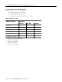
To Use publication
Install your chassis
Installation du châssis
Installation des Chassis
Installazione dello chassis
Instalar el chasis
Instalar o chassi
1746-IN016
Install your power supply
Installation de l’alimentation
Installation des Netzteils
Installazione dell’alimentatore
Instalar la fuente de alimentación eléctrica
Instalar a fonte de energia
1746-IN004
Install your processor
Installation de processeur
Installation des Prozessors
Installazione del processore
Instalar el procesador
Instalar o processador
1747-IN009
Topic Page
English Section 3
Section en français 15
Deutscher Abschnitt 27
Sezione in Italiano 39
Sección en español 51
Seção em português 63
Allen-Bradley Automation

2 SLC 5/03, SLC 5/04, and SLC 5/05 Modular Processors
Publication 1747-IN009E-MU-P - April 2007

Publication 1747-IN009E-MU-P - April 2007
Installation Instructions
English Section
SLC 5/03, SLC 5/04, and SLC 5/05 Modular
Processors
Catalog Numbers 1747-L531, 1747-L532, 1747-L533
1747-L541, 1747-L542, 1747-L543,
1747-L551, 1747-L552, 1747-L553
Topic Page
Safety Considerations 5
Hazardous Location Considerations 5
Required Tools and Equipment 6
Install the SLC Processor 7
Apply Power to the Processor 7
Loading Your Software 8
Establish Communication to the Processor 8
Replace the Battery 9
Troubleshooting Your SLC Processor 11
Specifications 11
Communication 12
Memory Backup 13
Battery Handling, Storing, and Transporting (Cat. No. 1747-BA) 13
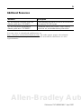
Additional Resources 75
Allen-Bradley Automation

4 SLC 5/03, SLC 5/04, and SLC 5/05 Modular Processors
Publication 1747-IN009E-MU-P - April 2007
Important User Information
Solid state equipment has operational characteristics differing from those of electromechanical equipment.
Safety Guidelines for the Application, Installation and Maintenance of Solid State Controls (publication
SGI-1.1 available from your local Rockwell Automation sales office or online at
http://literature.rockwellautomation.com
) describes some important differences between solid state
equipment and hard-wired electromechanical devices. Because of this difference, and also because of the
wide variety of uses for solid state equipment, all persons responsible for applying this equipment must
satisfy themselves that each intended application of this equipment is acceptable.
In no event will Rockwell Automation, Inc. be responsible or liable for indirect or consequential damages
resulting from the use or application of this equipment.
The examples and diagrams in this manual are included solely for illustrative purposes. Because of the many
variables and requirements associated with any particular installation, Rockwell Automation, Inc. cannot
assume responsibility or liability for actual use based on the examples and diagrams.
No patent liability is assumed by Rockwell Automation, Inc. with respect to use of information, circuits,
equipment, or software described in this manual.
Reproduction of the contents of this manual, in whole or in part, without written permission of Rockwell
Automation, Inc., is prohibited.
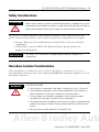
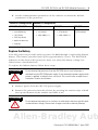
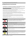
Throughout this manual, when necessary, we use notes to make you aware of safety considerations.
WARNING
Identifies information about practices or circumstances that can cause an explosion in
a hazardous environment, which may lead to personal injury or death, property
damage, or economic loss.
IMPORTANT
Identifies information that is critical for successful application and understanding of
the product.
ATTENTION
Identifies information about practices or circumstances that can lead to personal injury
or death, property damage, or economic loss. Attentions help you to identify a hazard,
avoid a hazard, and recognize the consequences.
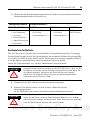
SHOCK HAZARD
Labels may be on or inside the equipment, for example, a drive or motor, to alert
people that dangerous voltage may be present.
BURN HAZARD
Labels may be on or inside the equipment, for example, a drive or motor, to alert
people that surfaces may reach dangerous temperatures.

SLC 5/03, SLC 5/04, and SLC 5/05 Modular Processors 5
Publication 1747-IN009E-MU-P - April 2007
Safety Considerations
For general recommendations concerning installation safety requirements and
safety related work practices, refer to the requirements specific to your region.
• Europe: Reference the standards found in EN 60204 and your national
regulations.
• United States: refer to NFPA 70E, Electrical Safety Requirements for
Employee Workplaces.
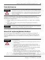
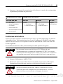
Hazardous Location Considerations
This equipment is suitable for use in Class I, Division 2, Groups A, B, C, D or
non-hazardous locations only. The following WARNING statement applies to use in
hazardous locations.
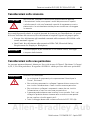
ATTENTION
Never install, remove, or wire any module while power is applied. Also, do not
expose processor modules to surfaces or other areas that may typically hold an
electrostatic charge. Electrostatic charges can alter or destroy memory.
IMPORTANT
See page 13 for information on proper battery handling, storage, and
transporting.
WARNING
EXPLOSION HAZARD
• Substitution of components may impair suitability for Class I, Division 2.
• Do not replace components or disconnect equipment unless power has
been switched off or the area is known to be non-hazardous.
• Do not connect or disconnect components unless power has been
switched off or the area is known to be non-hazardous.
• This product must be installed in an enclosure. All cables connected to the
product must remain in the enclosure or be protected by conduit or other
means.
• All wiring must comply with N.E.C. article 501-4(b).
Allen-Bradley Automation

6 SLC 5/03, SLC 5/04, and SLC 5/05 Modular Processors
Publication 1747-IN009E-MU-P - April 2007
Required Tools and Equipment
• medium blade screwdriver
• programming equipment
• appropriate network interface or cable
Cable Requirements
Network Interface Processor
SLC 5/03 SLC 5/04 SLC 5/05
1747-UIC
X
(1)
(1)
requires 1747-C13 or 1747-CP3 cable
X
(4)
(4)
requires 1747-CP3 cable
X
(4)
1747-PIC X
1747-CP3 X X X
1784-PKTX(D)
X
(2)
(2)
requires 1784-CP14 cable
X
1784-PCMK
X
(3)
(3)
requires 1784-PCM4 cable
X
(5)
(5)
requires 1784-PCM6 cable
10/100Base-T Ethernet X

SLC 5/03, SLC 5/04, and SLC 5/05 Modular Processors 7
Publication 1747-IN009E-MU-P - April 2007
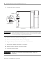
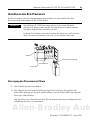
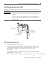
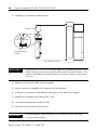
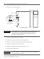
Install the SLC Processor
Make sure system power is off; then insert the processor into slot 0 of the 1746
chassis.
Apply Power to the Processor
1. Energize the chassis power supply.
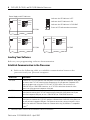
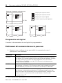
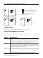
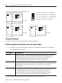
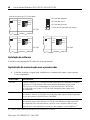
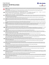
2. Check the chassis power supply and processor LED indicators. The power
LED indicator on the power supply should be on and the fault LED indicator
on the processor should be flashing.
See the figure on page 8 for location of the power supply and processor LED
indicators.
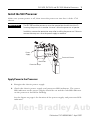
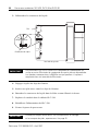
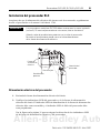
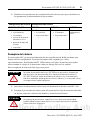
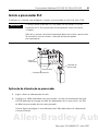
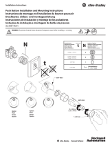
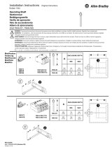
IMPORTANT
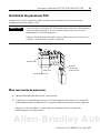
The SLC 500 modular processors must be inserted into the left slot (slot 0).
Inserting the processor in another slot won’t allow the processor to operate.
In addition, remove the protective wrap after installing the processor. Failure to
remove the wrap can cause the power supply to overheat.
Power
Supply
Protective Wrap
Card Guide
Processor Release
Allen-Bradley Automation

8 SLC 5/03, SLC 5/04, and SLC 5/05 Modular Processors
Publication 1747-IN009E-MU-P - April 2007
Loading Your Software
Refer to your programming software documentation.
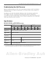
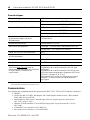
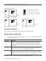
Establish Communication to the Processor
1. Refer to the following table to establish communication between the
processor and your personal computer.
Processor Procedure
SLC 5/03 Connect the 1747-PIC interface from the processor to your personal computer serial port
or connect the 1747-UIC interface from the processor to your personal computer USB
port to the processor using the 1747-C13 or 1747-CP3 cable. You can also use a
1784-PKTX(D) or 1784-PCMK interface, or a 1747-CP3 cable from channel 0 of the
processor to the personal computer serial port.
SLC 5/04 Connect a 1747-CP3 cable from channel 0 of the processor to the personal computer
serial port or connect the 1747-UIC interface from channel 0 of the processor to your
personal computer USB port, or use a 1784-PKTX(D) or 1784-PCMK interface.
SLC 5/05 Connect a 1747-CP3 cable from channel 0 of the processor to the personal computer
serial port, or connect the 1747-UIC interface converter from channel 0 of the processor
to your personal computer USB port. For Ethernet connection, connect channel 1 of the
processor and the PC Ethernet Card to an Ethernet hub using 10/100Base-T compatible
cable.
(1)
(1)
EtherNet/IP address must first be set via BOOTP or an RS-232 connection.
POWER
RUN
FLT
BATT
FORCE
DH485
RS232
POWER
RUN
FLT
BATT
FORCE
DH+
RS232
POWER
RUN
FLT
BATT
FORCE
ENET
RS232
Power Supply and LED Indicators
Indicates the LED indicator is OFF.
Indicates the LED indicator is ON.
Indicates the LED indicator is FLASHING.
Status of LED indicator does not matter.
SLC 5/05
SLC 5/04
SLC 5/03

SLC 5/03, SLC 5/04, and SLC 5/05 Modular Processors 9
Publication 1747-IN009E-MU-P - April 2007
2. Set the communication parameters of the software to match the default
parameters of the processor.
Replace the Battery
Your SLC processor provides back-up power for RAM through a replaceable lithium
battery. This battery provides back-up for approximately 2 years. The BATT LED
indicator on the front of the processor alerts you when the battery voltage has
fallen below a threshold level.
To replace the lithium battery follow these steps.
1. Remove power from the SLC 500 power supply.
2. Remove the processor from the chassis by pressing the retainer clips at both
the top and bottom of the module and slide it out.
Channel 0 Configuration Channel 1 Configuration
SLC 5/03, 5/04, 5/05 SLC 5/03 SLC 5/04 SLC 5/05
DF1 Full-duplex:
• no handshaking
• 19.2 Kbaud
• CRC Error Check
• duplicate detect on
• no parity
DH-485:
• 19.2 Kbaud
• node address = 1
DH+:
• 57.6 Kbaud
• node address = 1
Ethernet:
BOOTP enabled
ATTENTION
Do not remove the processor from the SLC 500 chassis until all power is
removed from the SLC 500 power supply. If you remove the power supply while
power is applied, an electrical arc can occur. This could cause an explosion in
hazardous location installations.
ATTENTION
Do not expose the processor to surfaces or other areas that may typically hold
an electrostatic charge. Electrostatic charges can alter or destroy memory.
Allen-Bradley Automation

10 SLC 5/03, SLC 5/04, and SLC 5/05 Modular Processors
Publication 1747-IN009E-MU-P - April 2007
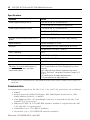
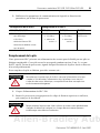
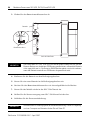
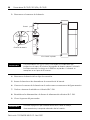
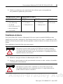
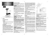
3. Unplug the battery connector.
4. Remove the battery from the retaining clips.
5. Insert a new battery into the battery retaining clips.
6. Plug the battery connector into the socket as shown above.
7. Re-insert the module into the SLC 500 chassis.
8. Restore power to the SLC 500 power supply.
9. Close the processor door.
IMPORTANT
The SLC 5/03, 5/04, and 5/05 processors have a capacitor that provides at least
30 minutes of battery back-up while the battery is disconnected. Data in RAM
is not lost if the battery is replaced within 30 minutes.
IMPORTANT
See page 13 for information on proper battery handling, storage, and
transporting.
White
Red
Battery Connector
Left Side View
Battery

SLC 5/03, SLC 5/04, and SLC 5/05 Modular Processors 11
Publication 1747-IN009E-MU-P - April 2007
Troubleshooting Your SLC Processor
Before troubleshooting your SLC 500 system, please obtain an SLC 500 Modular
Hardware Style User Manual, publication 1747-UM011. Refer to the chapter on
troubleshooting.
In addition to the SLC 500 Modular Hardware Style User Manual, publication
1747-UM011, the SLC 500 Instruction Set Reference Manual, publication
1747-RM001, contains explanations and examples for the entire instruction set as
well as for all status words and bits. It also contains explanations for all possible
fault codes found in status word S:6.
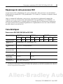
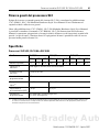
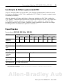
Specifications
SLC 5/03, SLC 5/04, and SLC 5/05 Processors
Attribute SLC 5/03 SLC 5/04 SLC 5/05
L531 L532 L533 L541 L542 L543 L551 L552 L553
Memory (words) 8 K 16 K 32 K 16 K 32 K 64 K 16 K 32 K 64 K
I/O capacity,
max
4096 discrete inputs/4096 discrete outputs
Local system,
max
3 chassis / 30 slots
Programming
instructions
107
Typical scan
time
(1)
(1)
The scan times are typical for a 1 K ladder logic program consisting of simple ladder logic and communication servicing.
Actual scan times depend on your program size, instructions used, and the communication protocol.
1 ms/K 0.9 ms/K
Bit execution
(XIC)
0.44 µs 0.37 µs
Programming
software
SLC 5/03s and SLC 5/04s: RSLogix 500,
SLC 5/05s: RSLogix 500
Allen-Bradley Automation

12 SLC 5/03, SLC 5/04, and SLC 5/05 Modular Processors
Publication 1747-IN009E-MU-P - April 2007
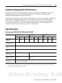
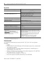
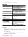
Communication
Communication options for the SLC 5/03, 5/04, and 5/05 processors are as follows:
• DH485
• RS-232 protocols (DF1 Full-duplex, DF1 Half-duplex master/slave, DF1
Radio Modem, DH-485, or ASCII)
• Data Highway Plus (A ControlLogix Gateway is required for the SLC 5/03
and SLC 5/05 processors.)
• Ethernet TCP/IP (A 1761-NET-ENI interface module is required for the SLC
5/03 and SLC 5/04 processors)
• ControlNet (via a 1747-KFC15 module)
• DeviceNet (via a 1761-NET-DNI interface module)
Specifications
Attribute Value
Power supply loading at 5V dc 500 mA for the SLC 5/03 processor
1.0 A for the SLC 5/04 and 5/05 processors
Power supply loading at 24V dc 175 mA for the SLC 5/03 processor
0 mA for the SLC 5/04 processor
(1)
(1)
SLC 5/04 Processors manufactured prior to April 2002 draw 200 mA at 24V dc. Check your label to verify your processor’s
current draw.
0 mA for the SLC 5/05 processor
Program scan hold-up time after loss of
power
20 ms...3 s (dependent on power supply loading)
Noise immunity NEMA Standard ICS 2-230
Vibration Displacement: 0.015 in., peak-to-peak at 5-57 Hz
Acceleration: 2.5 g at 57...2000 Hz
Shock, operating 30 g
Ambient temperature rating, operating 0...60 °C (32...140 °F)
Ambient temperature rating, storage -40...85 °C (-40...185 °F)
Humidity 5 to 95% without condensation
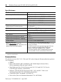
Agency certification
See http://ab.com
for declarations of
conformity, certificates, and other
certification details.
UL Listed Industrial Control Equipment
C-UL Listed Industrial Control Equipment for use in
Canada
UL Listed Industrial Control Equipment for use in
Class I, Division 2, Hazardous Locations Groups A, B,
C or D
CE compliant for all applicable directives
C-Tick marked for all applicable acts

SLC 5/03, SLC 5/04, and SLC 5/05 Modular Processors 13
Publication 1747-IN009E-MU-P - April 2007
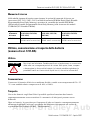
Memory Backup
The following table shows the memory backup options for the SLC 5/03, 5/04, and
5/05 processors. Flash EPROMs (Flash Erasable Programmable Read Only Memory)
combine the versatility of EEPROMs (Electrically-Erasable Programmable Read Only
Memory) with the security of UVPROMs (UV-Erasable PROM).
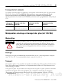
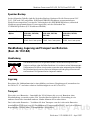
Battery Handling, Storing, and Transporting (Cat. No. 1747-BA)
Handling
Storing
Store the lithium batteries in a cool, dry environment, typically 20...25 °C
(68...77 °F) and 40% to 60% relative humidity.
Transporting
One or Two Batteries - Up to two batteries can be shipped together within the
United States without restriction. Regulations governing shipment to or within other
countries may differ.
Three or More Batteries - Procedures for the transportation of three or more
batteries shipped together within the United States are specified by the Department
of Transportation (DOT) in the Code of Federal Regulations, CFR49,
“Transportation.”
An exemption to these regulations, DOT - E7052, covers the transport of certain
hazardous materials classified as flammable solids. This exemption authorizes
Memory
Backup Option
SLC 5/03 Processor
(1747-L531, 1747-L532,
1747-L533)
SLC 5/04 Processor
(1747-L541, 1747-542,
1747-543)
SLC 5/05 Processor
(1747-L551, 1747-552,
1747-553)
Flash EPROM 1747-M13
(OS302 Series C or later)
1747-M13
(OS401 Series C or later)
1747-M13
(OS501 Series C or later)
ATTENTION
Do not charge the batteries. An explosion could result or the cells could
overheat causing burns. Do not open, puncture, crush, or otherwise mutilate
the batteries. An explosion may result and/or toxic, corrosive, and flammable
liquids would be exposed.
Allen-Bradley Automation

14 SLC 5/03, SLC 5/04, and SLC 5/05 Modular Processors
Publication 1747-IN009E-MU-P - April 2007
transport of lithium batteries by motor vehicle, rail freight, cargo vessel, and
cargo-only aircraft, providing certain conditions are met. Transport by passenger
aircraft is not permitted.
Shipment of depleted batteries for disposal may be subject to specific regulation of
the countries involved or to regulations endorsed by those countries, such as the
IATA Restricted Articles Regulations of the International Air Transport Association,
Geneva, Switzerland.
For disposal, batteries must be packaged and shipped in accordance with
transportation regulations, to a proper disposal site. The U.S. Department of
Transportation authorizes shipment of “Lithium batteries for disposal” by motor
vehicle only in regulation 173.1015 of CFR 49 (effective January 5, 1983). For
additional information contact:
U.S. Department of Transportation
Research and Special Programs Administration
400 Seventh Street, S.W.
Washington, D.C. 20590
Although the Environmental Protection Agency at this time has no regulations
specific to lithium batteries, the material contained may be considered toxic,
reactive, or corrosive. The person disposing of the material is responsible for any
hazard created in doing so. State and local regulations may exist regarding the
disposal of these materials.
For a lithium battery material safety data sheet, contact the manufacturer.
IMPORTANT
Regulations for transportation of lithium batteries are periodically revised.
Refer to http://www.dot.gov
for the latest shipping information.
ATTENTION
Do not incinerate or dispose of lithium batteries in general trash collection.
Explosion or violent rupture is possible. Batteries should be collected for
disposal in a manner to prevent against short circuiting, compacting, or
destruction of case integrity and hermetic seal.
Sanyo Energy Corporation
600 Supreme Drive
Bensenville, IL 60106
USA
Tadarand U.S. Battery Division
2 Seaview Blvd.
Port Washington, NY 11050
USA
or

Publication 1747-IN009E-FR-P - Avril 2007
Notice d'installation
Section en français
Processeurs modulaires SLC 5/03, SLC 5/04
et SLC 5/05
Références 1747-L531, 1747-L532, 1747-L533
1747-L541, 1747-L542, 1747-L543,
1747-L551, 1747-L552, 1747-L553
Sujet Page
Consignes de sécurité 17
Environnements dangereux 17
Outils et équipement requis 18
Installation du processeur SLC 19
Mise sous tension du processeur 19
Chargement de votre logiciel 20
Etablissement de la communication avec le processeur 20
Remplacement de la pile 21
Dépannage de votre processeur SLC 23
Caractéristiques 23
Communications 24
Sauvegarde de la mémoire 25
Manipulation, stockage et transport des piles (réf. 1747-BA) 25
Additional Resources 75
Allen-Bradley Automation

16 Processeurs modulaires SLC 5/03, SLC 5/04 et SLC 5/05
Publication 1747-IN009E-FR-P - Avril 2007
Informations importantes destinées à l'utilisateur
Les équipements électroniques possèdent des caractéristiques de fonctionnement différentes de celles des
équipements électromécaniques. La publication SGI-1.1, Safety Guidelines for the Application, Installation
and Maintenance of Solid State Controls (disponible auprès de votre agence commerciale Rockwell
Automation ou en ligne sur le site http://literature.rockwellautomation.com
), décrit certaines de ces
différences. En raison de ces différences et de la diversité des utilisations des équipements électroniques,
les personnes qui en sont responsables doivent s'assurer de l'acceptabilité de chaque application.
La société Rockwell Automation, Inc. ne saurait en aucun cas être tenue pour responsable ni être redevable
des dommages indirects ou consécutifs à l'utilisation ou à l'application de cet équipement.
Les exemples et schémas contenus dans ce manuel sont présentés à titre indicatif seulement. En raison du
nombre important de variables et d'impératifs associés à chaque installation, la société Rockwell Automation,
Inc. ne saurait être tenue pour responsable ni être redevable des suites d'utilisation réelle basée sur les
exemples et schémas présentés dans ce manuel.
La société Rockwell Automation, Inc. décline également toute responsabilité en matière de propriété
intellectuelle et industrielle concernant l'utilisation des informations, circuits, équipements ou logiciels
décrits dans ce manuel.
Toute reproduction totale ou partielle du présent document sans autorisation écrite de la société Rockwell
Automation, Inc. est interdite.
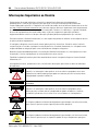
Des remarques sont utilisées tout au long de ce manuel pour attirer votre attention sur les mesures
de sécurité à prendre en compte :
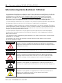
AVERTISSEMENT
Actions ou situations susceptibles de provoquer une explosion en environnement
dangereux et d'entraîner des blessures pouvant être mortelles, des dégâts matériels
ou des pertes financières.
IMPORTANT
Informations particulièrement importantes dans le cadre de l'utilisation du produit.
ATTENTION
Actions ou situations risquant d'entraîner des blessures pouvant être mortelles,
des dégâts matériels ou des pertes financières. Ces mises en garde vous aident
à identifier un danger, à éviter ce danger et à en discerner les conséquences.
DANGER
D'ELECTROCUTION
L'étiquette ci-contre, placée sur l’équipement ou à l’intérieur (un variateur ou un
moteur, par ex.), signale la présence éventuelle de tensions électriques dangereuses.
RISQUE DE
BRULURE
L'étiquette ci-contre, placée sur l’équipement ou à l’intérieur (un variateur ou un
moteur, par ex.) indique que certaines surfaces peuvent atteindre des
températures particulièrement élevées.

Processeurs modulaires SLC 5/03, SLC 5/04 et SLC 5/05 17
Publication 1747-IN009E-FR-P - Avril 2007
Consignes de sécurité
Pour connaître les recommandations générales relatives aux impératifs de sécurité
d'installation et de protection des postes de travail, conformez-vous à la réglementation
locale en vigueur.
• Europe : reportez-vous à la norme EN 60204 et aux réglementations nationales.
• Etats-Unis : reportez-vous à la norme NFPA 70E, Electrical Safety Requirements
for Employee Workplaces.
Environnements dangereux
Cet équipement est adapté à une utilisation en environnements de Classe I, Division 2,
Groupes A, B, C, D ou dans des environnements non dangereux. La mise en garde
suivante porte sur une utilisation en environnement dangereux.
ATTENTION
Ne jamais installer, retirer ou câbler un module sous tension. Ne pas exposer
les modules processeurs à des surfaces ou autres zones généralement
chargées en électricité statique. Les charges électrostatiques peuvent
endommager voire détruire la mémoire.
IMPORTANT
Pour de plus amples informations sur la manipulation, le stockage
et le transport des piles, reportez-vous à la page 25.
AVERTISSEMENT
DANGER D'EXPLOSION
• La substitution de composants peut rendre cet équipement impropre
à une utilisation en environnement de Classe I, Division 2.
• Ne pas remplacer de composants ou déconnecter l'équipement sans
s'être assuré que l'alimentation est coupée et que l'environnement
est classé non dangereux.
• Ne pas connecter ou déconnecter des composants sans s'être assuré
que l'alimentation est coupée et que l'environnement est classé non
dangereux.
• Ce produit doit être installé dans une armoire. Tous les câbles qui lui sont
connectés doivent rester dans l’armoire ou être protégés par un conduit ou
par d’autres moyens.
• L'ensemble du câblage doit être conforme aux normes d'électricité
en vigueur dans le pays où l'appareil est utilisé.
Allen-Bradley Automation

18 Processeurs modulaires SLC 5/03, SLC 5/04 et SLC 5/05
Publication 1747-IN009E-FR-P - Avril 2007
Outils et équipement requis
• un tournevis plat moyen ;
• un équipement de programmation ;
• un câble ou une interface réseau approprié(e).
Câbles requis
Interface réseau Processeur
SLC 5/03 SLC 5/04 SLC 5/05
1747-UIC
X
(1)
(1) câble 1747-C13 ou 1747-CP3 requis
X
(4)
(4) câble 1747-CP3 requis
X
(4)
1747-PIC X
1747-CP3 X X X
1784-PKTX(D)
X
(2)
(2) câble 1784-CP14 requis
X
1784-PCMK
X
(3)
(3) câble 1784-PCM4 requis
X
(5)
(5) câble 1784-PCM6 requis
Ethernet 10/100Base-T X

Processeurs modulaires SLC 5/03, SLC 5/04 et SLC 5/05 19
Publication 1747-IN009E-FR-P - Avril 2007
Installation du processeur SLC
Assurez-vous que le système est hors tension, puis introduisez le processeur dans
l'emplacement 0 du châssis 1746.
Mise sous tension du processeur
1. Mettez l'alimentation du châssis sous tension.
2. Vérifiez les voyants du processeur et de l'alimentation du châssis. Le voyant de
l'alimentation doit être allumé et le voyant de défaut du processeur doit clignoter.
Reportez-vous à la figure 20 pour repérer l'emplacement des voyants de
l'alimentation et du processeur.
IMPORTANT
Les processeurs modulaires SLC 500 doivent être insérés dans l'emplacement
de gauche (emplacement 0). Si vous insérez le processeur dans un autre
emplacement, il ne fonctionnera pas.
Retirez la bande de protection après avoir installé le processeur. Dans le cas
contraire, l'alimentation risque de surchauffer.
Alimentation
Bande de protection
Guide-carte
Patte de
verrouillage
du processeur
Allen-Bradley Automation

20 Processeurs modulaires SLC 5/03, SLC 5/04 et SLC 5/05
Publication 1747-IN009E-FR-P - Avril 2007
Chargement de votre logiciel
Consultez la documentation de votre logiciel de programmation.
Etablissement de la communication avec le processeur
1. Reportez-vous au tableau suivant pour établir la communication entre le
processeur et votre ordinateur.
Processeur Procédure
SLC 5/03 Raccordez l'interface 1747-PIC entre le processeur et le port série de votre l'ordinateur,
ou l'interface 1747-UIC entre le processeur et le port USB de votre ordinateur, au moyen
d'un câble 1747-C13 ou 1747-CP3. Vous pouvez également utiliser une interface
1784-PKTX(D) ou 1784-PCMK, ou un câble 1747-CP3 entre la voie 0 du processeur
et le port série de l'ordinateur.
SLC 5/04 Utilisez un câble 1747-CP3 pour raccorder la voie 0 du processeur au port série
de l'ordinateur, ou l'interface 1747-UIC pour raccorder la voie 0 du processeur au port
USB de l'ordinateur, ou encore utilisez une interface 1784-PKTX(D) ou 1784-PCMK.
SLC 5/05 Utilisez un câble 1747-CP3 pour raccorder la voie 0 du processeur au port série
de l'ordinateur, ou le convertisseur d'interface 1747-UIC pour raccorder la voie 0 du
processeur au port USB de l'ordinateur. Pour une connexion Ethernet, connectez la voie 1
du processeur et la carte Ethernet du PC à un hub Ethernet à l’aide d’un câble
compatible 10Base-T.
(1)
(1) L'adresse EtherNet/IP doit d'abord être définie via BOOTP ou une connexion RS-232.
POWER
RUN
FLT
BATT
FORCE
DH485
RS232
POWER
RUN
FLT
BATT
FORCE
DH+
RS232
POWER
RUN
FLT
BATT
FORCE
ENET
RS232
Voyants de l'alimentation et du processeur
Indique que le voyant est éteint.
Indique que le voyant est allumé.
Indique que le voyant clignote.
L'état du voyant n'a pas d'importance.
SLC 5/05
SLC 5/04
SLC 5/03
A página está carregando...
A página está carregando...
A página está carregando...
A página está carregando...
A página está carregando...
A página está carregando...
A página está carregando...
A página está carregando...
A página está carregando...
A página está carregando...
A página está carregando...
A página está carregando...
A página está carregando...
A página está carregando...
A página está carregando...
A página está carregando...
A página está carregando...
A página está carregando...
A página está carregando...
A página está carregando...
A página está carregando...
A página está carregando...
A página está carregando...
A página está carregando...
A página está carregando...
A página está carregando...
A página está carregando...
A página está carregando...
A página está carregando...
A página está carregando...
A página está carregando...
A página está carregando...
A página está carregando...
A página está carregando...
A página está carregando...
A página está carregando...
A página está carregando...
A página está carregando...
A página está carregando...
A página está carregando...
A página está carregando...
A página está carregando...
A página está carregando...
A página está carregando...
A página está carregando...
A página está carregando...
A página está carregando...
A página está carregando...
A página está carregando...
A página está carregando...
A página está carregando...
A página está carregando...
A página está carregando...
A página está carregando...
A página está carregando...
A página está carregando...
-
 1
1
-
 2
2
-
 3
3
-
 4
4
-
 5
5
-
 6
6
-
 7
7
-
 8
8
-
 9
9
-
 10
10
-
 11
11
-
 12
12
-
 13
13
-
 14
14
-
 15
15
-
 16
16
-
 17
17
-
 18
18
-
 19
19
-
 20
20
-
 21
21
-
 22
22
-
 23
23
-
 24
24
-
 25
25
-
 26
26
-
 27
27
-
 28
28
-
 29
29
-
 30
30
-
 31
31
-
 32
32
-
 33
33
-
 34
34
-
 35
35
-
 36
36
-
 37
37
-
 38
38
-
 39
39
-
 40
40
-
 41
41
-
 42
42
-
 43
43
-
 44
44
-
 45
45
-
 46
46
-
 47
47
-
 48
48
-
 49
49
-
 50
50
-
 51
51
-
 52
52
-
 53
53
-
 54
54
-
 55
55
-
 56
56
-
 57
57
-
 58
58
-
 59
59
-
 60
60
-
 61
61
-
 62
62
-
 63
63
-
 64
64
-
 65
65
-
 66
66
-
 67
67
-
 68
68
-
 69
69
-
 70
70
-
 71
71
-
 72
72
-
 73
73
-
 74
74
-
 75
75
-
 76
76


Allen-Bradley SLC 5/03 Installation Instructions Manual
- Tipo
- Installation Instructions Manual
em outras línguas
- español: Allen-Bradley SLC 5/03
- français: Allen-Bradley SLC 5/03
- italiano: Allen-Bradley SLC 5/03
- English: Allen-Bradley SLC 5/03
- Deutsch: Allen-Bradley SLC 5/03
Artigos relacionados
-
 Allen-Bradley SLC 5/03 Installation Instructions Manual
-
 Allen-Bradley SLC 5/03 Installation Instructions Manual
-
 Allen-Bradley 1747-L524 Guia de instalação
-
 Allen-Bradley 800T-NGCY Installation And Mounting Instructions
-
 Allen-Bradley Guardmaster 440C-ENET Original Instructions
-
 Allen-Bradley Kinetix 2000 Installation Instructions Manual
-
 Allen-Bradley 194U-S1 Guia de instalação


Outros documentos
-
 Rockwell Automation 2711P-RC4 Installation Instructions Manual
-
 Casalux GT-SLC-AM-02 Manual do usuário
-
Vision TC2-TILT Manual do usuário
-
SMAR ENET-710 Manual do usuário
-
Vision SP-5000P Manual do proprietário
-
Dell Studio 1749 Manual do usuário
-
Dell studio 1747 Guia rápido
-
Bontrager Elite Road Pedal Manual do usuário
-
Bosch Appliances FPE-1000-SLC Manual do usuário
-
Proceq 54257 Guia de usuario

