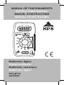
KPS MT10 Manual do proprietário
- Categoria
- Multímetros
- Tipo
- Manual do proprietário

Multímetro digital
Digital multimeter
Multimètre numérique
Multímetro digital
KPS-MT10
602250005
KPS-MT10
MANUAL DE FUNCIONAMIENTO
INSTRUCTIONS MANUAL
MANUEL D’INSTRUCTIONS
MANUAL DE INSTRUÇÕES

2
KPS-MT10 • Multímetro digital
ESP
1. INTRODUCCIÓN
Este dispositivo ha sido diseñado de acuerdo con la nor-
ma IEC-1010 referida a los instrumentos de medición
electrónicos con una categoría de sobretensión (CATII)
y con un nivel de contaminación 2.
Siga todas las instrucciones de uso y de seguridad para
garantizar que el dispositivo se usa de un modo seguro y
se mantiene en buenas condiciones.
Haciendo un uso apropiado del mismo y teniendo el cui-
dado oportuno, su multímetro digital le proporcionará
años de servicio satisfactorio.
2. REGLAS DE SEGURIDAD
Durante el uso
• Nunca exceda el límite de protección indicado en las
especicacionesparacadaescalademedición.
• Nunca use el instrumento para medir voltajes que
puedan exceder los 600 V sobre la toma a tierra en
instalaciones con categoría II.
• Tenga siempre cuidado al trabajar con voltajes
superiores a los 60 V CC o 30 V CA rms.Mantenga
los dedos por detrás de los límites de la sonda durante
la medición.
• No realice mediciones de resistencia en circuitos
activos.
• Revise las tomas y sondas en busca de roturas,
grietas o daños en el aislamiento antes de usar el
instrumento.

3
KPS-MT10 • Multímetro digital
ESP
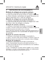
Símbolos de seguridad
Información importante sobre seguridad,
consulte el manual de instrucciones
Toma a tierra
Indica que cumple con los requisitos de
doble aislamiento
El fusible debe reemplazarse por otro con los
valoresespecicadosenelmanual.
Mantenimiento
• Antes de abrir la carcasa, desconecte siempre las
tomas de prueba de cualquier circuito con energía.
• Para lograr una protección continuada frente a
incendios, reemplace siempre el fusible por otro con
los valores: F 500mA/250V (Actuación rápida).
• No use nunca el medidor si la cubierta trasera no está
en su sitio y perfectamente cerrada.
• No use productos abrasivos ni disolventes en el
medidor. Para limpiarlo use sólo un paño seco y un
detergente neutro.
Descripción general
Este multímetro digital compacto ha sido diseñado para
medir voltajes de CA y CC, corriente CA y CC, resisten-
cia, para realizar pruebas de diodos y para hacer prue-
bas de continuidad audible con facilidad y precisión.
La precisión está garantizada por 1 año, 23°C±5°C, hu-
medad relativa inferior al 75%.

4
KPS-MT10 • Multímetro digital
ESP
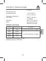
3. CARACTERÍSTICAS GENERALES
Voltaje máximo entre
terminales y toma a tierra CAT II 600 V
Protección del fusible F 500mA/250V
Alimentación 2 pilas de 3 V, SR
44 o LR 44
Pantalla de cristal líquido,
conteo de 3999,
actualizaciones
cada 2-3 segundos
Método de medición Convertidor
corriente alterna/
continua
con integración de
doble vertiente.
Indicación de sobreescala Símbolo “OL” en la
pantalla.
Indicación de polaridad se muestra “-” para
polaridad negativa
Temperatura de
funcionamiento 0°C a 40°C (32°F a
104°F)
Temperatura de almacenamiento -10°C a 50°C (10°F
a 122°F)
Indicación de batería baja “BATT “aparece en
el display.
Tamaño 120 x 70 x 18 mm
Peso aproximado 110g.
baterías incluidas.

5
KPS-MT10 • Multímetro digital
ESP
TENSION EN CONTINUA
Escala Resolución Precisión
4V 1mV +/-0,5% de lect.+2 dígitos
40V 10mV
+/-0,8% de lect. +2 dígitos400V 0,1V
600V 1V
Impedanciadeentrada:10MΩ
Entrada máxima: 600V DC
TENSION EN ALTERNA
Escala Resolución Precisión
4V 1mV
+/-0,5% de lect.+/-2 dígitos
40V 10mV
400V 0,1V
600V 1V
ImpedanciadeEntrada:10MΩ.
Escala de frecuencia:50 - 60 Hz para escalas de 400V
y 600V
Entrada máxima: 600Vrms AC

6
KPS-MT10 • Multímetro digital
ESP
CORRIENTE CONTINUA
Escala Resolución Precisión
4mA 0,01mA +/-0,5% de lectura +/-2dígitos
400mA 0,1mA
Protección de sobrecarga: fusible de 0,5A / 250V
CORRIENTE ALTERNA
Escala Resolución Precisión
4mA 0,01mA +/-0,5% de lectura +/-3dígitos
400mA 0,1mA
Protección de sobrecarga: fusible de 0,5A / 250V.
RESISTENCIA
Escala Resolución Precisión
400Ω 0,1Ω
+/- 1,5% de lectura +/-2dígitos
4kΩ 1Ω
40kΩ 10Ω
400kΩ 100Ω
4MΩ 1kΩ
40MΩ 10kΩ +/- 3,0% de lectura +/-2dígitos
Protección de sobrecarga: 250Vrms AC
Tensión máxima a circuito abierto: 3,2V

7
KPS-MT10 • Multímetro digital
ESP
DIODOS
Escala Resolución Precisión
1mv 25μA 3V
Protección de sobrecarga: 250Vrms AC
CONTINUIDAD AUDIBLE
Resolución Descripción
0,1Ω El pitido incorporado suena si la
resistenciaesmenorde50Ω
Protección de sobrecarga: 250Vrms AC

8
KPS-MT10 • Multímetro digital
ESP
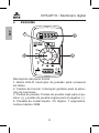
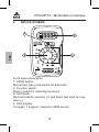
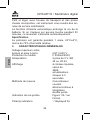
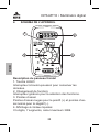
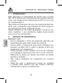
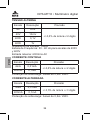
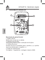
4. ESQUEMA
KPS-MT10
23
4
1
Descripción del panel frontal
1. Botón HOLD: Interruptor de pulsado para conservar
los datos.
2. Cambio de función: Interruptor giratorio para la selec-
ción de funciones.
3. Puntas de prueba: Puntas de prueba rojas para el po-
sitivo (+) y puntas de prueba negras para el negativo (-).
4. Pantalla de cristal líquido: 3¾ dígitos, 7 segmentos,
conteo máximo 3999.

9
KPS-MT10 • Digital multimeter
ENG
5. INSTRUCCIONES DE FUNCIONAMIENTO
Medición de voltaje en corriente continua
1. Sitúe el interruptor de función en la posición V .
2. Conecte las tomas de prueba a través de la fuente o
carga a medir. Se indicará la polaridad de la conexión de
la toma roja junto con el valor del voltaje.
Medición de voltaje en corriente alterna
1. Sitúe el interruptor de función en la posición V ~.
2. Conecte las tomas de prueba a través de la fuente o
carga a medir y lea el valor del voltaje en el display.
Medición de corriente continua
1. Sitúe el interruptor de función en la posición A .
2. Abra el circuito en el que se medirá la corriente y co-
necte las tomas de prueba en serie con el circuito.
3. El valor de la corriente de la toma roja aparece en el
display junto con la polaridad de la conexión de la toma
roja.
Medición de corriente alterna
1. Sitúe el interruptor de función en la posición A ~.
2. Abra el circuito en el que se medirá la corriente, co-
necte las tomas de prueba en serie con el circuito y lea
el display.
Medición de la resistencia
1.SitúeelinterruptordefunciónenlaposiciónΩ.
(Nota: La polaridad de la toma roja es positiva “+”).
2. Conecte las tomas de prueba a través de la resistencia
a medir y lea el valor en el display.
3. Si la resistencia a medir está conectada a un circuito,
desconecte el circuito y descargue todos los condensa-

10
KPS-MT10 • Digital multimeter
ENG
dores antes de aplicar las tomas de prueba.
4.Almedirresistenciasdemásde1MΩelmedidorne-
cesitará algunos segundos para lograr una lectura esta-
ble. Es algo normal en mediciones de resistencias altas.
Test de diodos
1. Sitúe el interruptor de función en la posición
(Nota: La polaridad de la toma roja es positiva “+”).
2. Conecte la toma de prueba roja al ánodo del diodo y la
toma negra al cátodo del diodo a probar.
3. Se mostrará la caída de voltaje aproximada del diodo.
Siseinviertelaconexión,sóloaparecerálagura“OL”
en el display.
Prueba de continuidad audible
1. Sitúe el interruptor de función en la posición .
2. Conecte las tomas de prueba a dos puntos del circui-
toaprobar.Silaresistenciaesinferiora50Ω,sonaráel
avisador acústico.
Aplicación de la retención de datos
El botón HOLD se usa para mantener el resultado de la
medición. Al presionar este botón, el display mantendrá
la última lectura hasta que se presione el botón de nuevo
o se gire el interruptor de función.
6. MANTENIMIENTO
Cambio de la pila y el fusible
Si aparece el signo “ “ en el display, deberá reempla-
zarse la pila. Retire el tornillo de la cubierta trasera y abra
la carcasa. Reemplace las pilas gastadas por otras del
mismo tipo.
Raramente es necesario reemplazar los fusibles y cuan-

11
KPS-MT10 • Digital multimeter
ENG
do lo es, suele deberse a un error del usuario. Abra la
carcasa y reemplace el fusible fundido con otro del mis-
mo valor.
Advertencia
Antes de intentar abrir la carcasa, asegúrese siempre de
que las tomas de prueba se han desconectado de los
circuitos a medir. Cierre la carcasa y apriete los tornillos
completamente antes de usar el medidor para evitar ries-
gos de descarga eléctrica. Para lograr una protección
continuada frente a incendios, reemplace siempre el fusi-
ble por otro con los valores: F 500mA/250V
Accesorios
Pila SR44 o LR44 2
Funda transportadora 1
Manual de instrucciones 1

12
KPS-MT10 • Digital multimeter
ENG
1. INTRODUCTION
This meter has been designed according to IEC-1010
concerning electronic measuring instruments with an
overvoltage category (CAT II) and pollution 2.
Follow all safety and operating instructions to ensure the
meter is used and safely and is kept in good condition.
With proper use and care, your digital multimeter will give
you years of satisfactory service.
2. SECURITY
During use
• Never exceed the protection limit indicated in the
specicationsforeachrangeofmeasurement.
• Never use the meter to measure voltages that might
exceed 600 V above earth ground in category II
installations.
• Always be careful when working with voltages above
60V DC or 30 V AC rms. Keep ngers behind the
probe barriers while measuring.
• Do not perform resistance measurements on live
circuits.
• Inspect test leads and probes for cracks, breaks or
crazes in the insulation before using the meter.
• Safety symbols
Important safety information, refer to the in-
struction manual
Earth ground

13
KPS-MT10 • Digital multimeter
ENG
Indicates compliance with requirements for
double insulation
Fusemustbereplacedwithratingsspecied
in the manual
Maintenance
• Before opening case, always disconnect test leads
from all energized circuits.
• For continuous protection against re, replace fuse
only with ratings: F 500mA/250V (Quick acting).
• Never use the meter unless the back cover is in place
and fastened conpletely.
• Do not use abrasives or solvets on the meter. To clean
it use only a damp cloth and mild detergent.
General description
This compact digital multimeter is designed to measure
AC and DC voltages, AC and DC current, resistance, di-
ode and to perform audible continuity checks with accu-
racy and ease.
Small and lightweight, with carryng case and test leads
wound on its body, this instrument will provide you years
of satisfactory service.
Auto power-off function extends the battery life. If no
keyinputs happen around 30 minutes, this meter will be
turned off automatically.
Specication
Accuracy is guaranteed for 1 year, 23°C±5°C, less than
75% RH.

14
KPS-MT10 • Digital multimeter
ENG
3. GENERAL CHARACTERISTICS
Maximum voltage between
terminals and earth
ground CAT II 600 V
Fuse protection F 500mA/250V
Power supply 23 V battery, SR
44 or LR 44 x 2
Display LCD, 3999 counts,
updates 2-3 sec
Measuring method Dual-slope
integration A/D con
verter
Overrange indication Figure “OL” on the
display
Polarity indication “-”displayed for
negative polarity
Operating temperature 0°C to 40°C (32°F
to 104°F)
Storage temperature -10°C to 50°C
(10°F to 122°F)
Low battery indication “BATT “ appears
on the display
Size 120 x 70 x 18 mm
Weight Approx. 110g.
including batteries.

15
KPS-MT10 • Digital multimeter
ENG
CONTINUOUS VOLTAGE
Scale Resolution Accuracy
4V 1mV +/-0,5% of reading+2 digits
40V 10mV
+/-0,8% of reading +2 digits400V 0,1V
600V 1V
ImpedanceofEntrance:10MΩ
Maximum entrance: 600V DC
ALTERNATING VOLTAGE
Scale Resolution Accuracy
4V 1mV
+/-0,5% of reading+/-2 digits
40V 10mV
400V 0,1V
600V 1V
ImpedanceofEntrance:10MΩ.
Scale of frequency: 50 - 60 Hz for scales of 400V and
600V
Maximum entrance: 600Vrms AC

16
KPS-MT10 • Multimètre numérique
FRA
DIRECT CURRENT
Scale Resolution Accuracy
4mA 0,01mA +/-0,5% of reading +/-2 digits
400mA 0,1mA
Protection of overload: fuse of 0,5A / 250V.
ALTERNATING CURRENT
Scale Resolution Accuracy
4mA 0,01mA +/-0,5% of reading +/-3 digits
400mA 0,1mA
Protection of overload: fuse of 0,5A / 250V.
RESISTANCE
Scale Resolution Accuracy
400Ω 0,1Ω
+/- 1,5% of reading +/-3 digits
4kΩ 1Ω
40kΩ 10Ω
400kΩ 100Ω
4MΩ 1kΩ
40MΩ 10kΩ +/- 3,0% of reading +/-2 digits
Protection of overload: 250Vrms AC
Maximum voltage to open circuit: 3,2V

17
KPS-MT10 • Multimètre numérique
FRA
DIODES
Scale Resolution Accuracy
1mv 25μA 3V
Protection of overload: 250Vrms AC.
AUDIBLE CONTINUITY
Resolution Description
0,1Ω
The incorporated bip audible one
sounds if the resistance is smaller of
50Ω
Protection of overload: 250Vrms AC
Scale Resolution Accuracy
4V 1mV +/-0,5% of reading+2 digits
40V 10mV
+/-0,8% of reading +2 digits400V 0,1V
600V 1V

18
KPS-MT10 • Multimètre numérique
FRA
4. DEVICE SCHEMA
KPS-MT10
23
4
1
Front panel description
1. HOLD button:
Momentary type push switch for data hold.
2. Function switch:
Rotary switch for selecting functions.
3. Test leads:
Red test lead for positive (+) and black test lead for neg-
ative (-).
4. LCD display:
3¾ digits, 7 segmet, maximum 3999 counts.

19
KPS-MT10 • Multimètre numérique
FRA
5. OPERATING INSTRUCTION
DC Voltage measurement
1. Set the function switch at V position.
2. Connect test leads across the source or load under
measurement. The polarity of red lead connection will be
indicated at the same time as the voltage value.
AC voltage measurement
1. Set the function switch at V ~ position.
2. Connect test leads across the source or load being
measurement and read the voltage value on the LCD dis-
play.
DC current measurement
1. Set the function switch at A position.
2. Open the circuit in which the current is to be measured
and connect test leads in series with the circuit.
3. Red current value on the LCD display along with the
polarity of red lead connection.
AC current measurement
1. Set the function switch at A ~ position.
2. Open the circuit in which the current is to be measured,
and connect test leads in series with the circuit and read
LCD display.
Resistance measurement
1.SetthefunctionswitchatΩposition.(Note:Thepolar-
ity of red lead is positive “+”).
2. Connect test leads across the resistor to be measured
and read LCD display.
3. If the resistor being measured is connected to a circuit,
turn off the power of the circuit and discharge all capaci-

20
KPS-MT10 • Multimètre numérique
FRA
tors before applying test leads.
4.Whenmeasuringresistanceabove1MΩthemeterwill
take a few seconds to get stable reading. It is normal for
high resistance mesurement.
Diode test
1. Set the function switch at position.
(Note: The polarity of red lead is positive “+”).
2. Connect the red test lead to the anode of the diode to
be tested ond the black lead to the cathode of the diode.
3. The approx. forward voltage drop of the diode will be
displayed.Iftheconnectionisreversed,onlygure“OL”
will appear on the LCD display.
Audible continuity test
1. Set the function switch at position.
2. Connect test leads to two points of the circuit to be
tested.
Data hold application
HOLD button is used to hold a measuring result. When
this button is pushed, LCD will keep the last reading until
pushing this button again or rotating the function switch.
6. MAINTENANCE
Battery & fuse replacement
If the sign “ “ appears on the LCD display, it indicates
that the battery should be replaced. Remove the screw
on the back cover and open the case. Replace the ex-
hausted batteries with the same types.
Fuse rarely need replacement and blow almost always
as a result of operator’s error. Open the case and replace
blown fuse with same ratings.
A página está carregando...
A página está carregando...
A página está carregando...
A página está carregando...
A página está carregando...
A página está carregando...
A página está carregando...
A página está carregando...
A página está carregando...
A página está carregando...
A página está carregando...
A página está carregando...
A página está carregando...
A página está carregando...
A página está carregando...
A página está carregando...
A página está carregando...
A página está carregando...
A página está carregando...
A página está carregando...
A página está carregando...
A página está carregando...
A página está carregando...
A página está carregando...
-
 1
1
-
 2
2
-
 3
3
-
 4
4
-
 5
5
-
 6
6
-
 7
7
-
 8
8
-
 9
9
-
 10
10
-
 11
11
-
 12
12
-
 13
13
-
 14
14
-
 15
15
-
 16
16
-
 17
17
-
 18
18
-
 19
19
-
 20
20
-
 21
21
-
 22
22
-
 23
23
-
 24
24
-
 25
25
-
 26
26
-
 27
27
-
 28
28
-
 29
29
-
 30
30
-
 31
31
-
 32
32
-
 33
33
-
 34
34
-
 35
35
-
 36
36
-
 37
37
-
 38
38
-
 39
39
-
 40
40
-
 41
41
-
 42
42
-
 43
43
-
 44
44


KPS MT10 Manual do proprietário
- Categoria
- Multímetros
- Tipo
- Manual do proprietário
em outras línguas
- español: KPS MT10 El manual del propietario
- français: KPS MT10 Le manuel du propriétaire
Artigos relacionados
Outros documentos
-
 LEXMAN LX-M-2000 Guia de usuario
-
koban KMD-S01 Manual do proprietário
-
Facom 714A Manual do proprietário
-
-
Expert E051301 Manual do usuário
-
Beta 1760/OHM Instruções de operação
-
Stanley FMHT0-77419 Manual do proprietário
-
Extech Instruments DM220 Manual do usuário
-
-
Profile 730660341 Manual do usuário
