
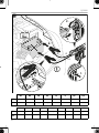
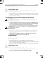
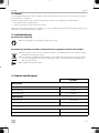
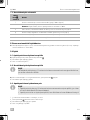
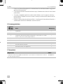
PJS1000
Jump starter with power bank
Operating manual. . . . . . . . . . . . . . . . . . . . 9
Starthilfegerät mit Powerbank
Bedienungsanleitung . . . . . . . . . . . . . . . . 23
Unité d’alimentation et de
démarrage d’appoint
Notice d’utilisation . . . . . . . . . . . . . . . . . . 38
Unidad de ayuda de arranque con
batería auxiliar
Instrucciones de uso . . . . . . . . . . . . . . . . . 53
Auxiliar de arranque com
carregador de bateria portátil
Manual de instruções . . . . . . . . . . . . . . . . 68
Avviatore di emergenza con
alimentatore portatile
Istruzioni per l’uso. . . . . . . . . . . . . . . . . . . 83
Starthulp met powerbank
Gebruiksaanwijzing . . . . . . . . . . . . . . . . .98
Starthjælp med powerbank
Betjeningsvejledning . . . . . . . . . . . . . . . 113
Starthjälp med batteribank
Bruksanvisning . . . . . . . . . . . . . . . . . . . . 128
Starthjelp med powerbank
Bruksanvisning . . . . . . . . . . . . . . . . . . . . 143
Akustollinen apukäynnistin
Käyttöohje. . . . . . . . . . . . . . . . . . . . . . . . 157
Urządzenie rozruchowe z
powerbankiem
Instrukcja obsługi . . . . . . . . . . . . . . . . . . 172
Skokový štartér s powerbankou
Návod na obsluhu . . . . . . . . . . . . . . . . . 187
Startovací zdroj s powerbankou
Návod k obsluze. . . . . . . . . . . . . . . . . . . 202
Segédindító akkumulátorral
Használati utasítás . . . . . . . . . . . . . . . . . 217
ﻙﻧﺑﺭﻭﺎﺑ ﻊﻣ ﻝﻳﻐﺷﺗﻟﺍ ءﺩﺑ ﺯﺎﻬﺟ
ﻝﻳﻐﺷﺗﻟﺍ ﻝﻳﻟﺩ . . . . . . . . . . . . . . . . . . . . . . . . . 232
INPUT 9V/2A
OUTPUT 12V/8A
EN
DE
FR
ES
PT
IT
NL
DA
SV
NO
FI
PL
SK
CS
HU
AR
POWER & CONTROL
JUMP STARTER

© 2023 Dometic Group. The visual appearance of the contents of this manual is protected
by copyright and design law. The underlying technical design and the products contained
herein may be protected by design, patent or be patent pending. The trademarks
mentioned in this manual belong to Dometic Sweden AB. All rights are reserved.

PJS1000
3
INPUT 9V/2A
OUTPUT 12V/8A
1 2 3
4
56
1

PJS1000
4
INPUT 9V/2A
OUTPUT 12V/8A
1 2 3
457 68
9
2
1 2 3
4
5
6
3

PJS1000
5
INPUT 9V/2A
OUTPUT 12V/8A
3.
3.
INPUT 9V/2A
OUTPUT 12V/8A
2.
A
B
1.
4
INPUT 9V/2A
OUTPUT 12V/8A
2x
+
1x
+
1x
+
1x
strobe
5

PJS1000
6
EN DE FR ES PT IT NL DA
bk Black Schwarz Noir Negro Preto Nero Zwart Sort
rd Red Rot Rouge Rojo Vermelho Rosso Rood Rød
SV NO FI RU PL SK CS HU AR
bk Svart Svart Musta Черный Czarny Čierna Černá Fekete ﺩﻭﺳﺃ
rd Röd Rød Punainen Красный Czerwony Červená Červená Piros ﺭﻣﺣﺃ
bk
3.
1.
2.
4.
5.
rd
6

PJS1000
7
rd
1.
3.
2.
4.
< 30 s
bk
7

PJS1000
8
INPUT 9V/2A
OUTPUT 12V/8A
2.
B
A
1.
3.
8
INPUT 9V/2A
OUTPUT 12V/8A
1.
2.
9

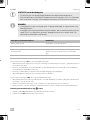
PJS1000 Explanation of symbols
EN
9
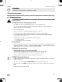
Please read these instructions carefully and follow all instructions, guidelines, and warnings included in this product
manual in order to ensure that you install, use, and maintain the product properly at all times. These instructions
MUST stay with this product.
By using the product, you hereby confirm that you have read all instructions, guidelines, and warnings carefully and
that you understand and agree to abide by the terms and conditions as set forth herein. You agree to use this prod-
uct only for the intended purpose and application and in accordance with the instructions, guidelines, and warn-
ings as set forth in this product manual as well as in accordance with all applicable laws and regulations. A failure to
read and follow the instructions and warnings set forth herein may result in an injury to yourself and others, damage
to your product or damage to other property in the vicinity. This product manual, including the instructions, guide-
lines, and warnings, and related documentation, may be subject to changes and updates. For up-to-date product
information, please visit documents.dometic.com.
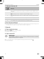
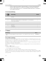
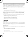
Contents
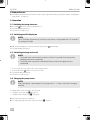
1 Explanation of symbols . . . . . . . . . . . . . . . . . . . . . . . . . . . . . . . . . . . . . . . . . . . . . . . . . . . . . . . . . . . . . . . . . . .9
2 Safety instructions . . . . . . . . . . . . . . . . . . . . . . . . . . . . . . . . . . . . . . . . . . . . . . . . . . . . . . . . . . . . . . . . . . . . . . 10
3 Safety precautions when handling batteries . . . . . . . . . . . . . . . . . . . . . . . . . . . . . . . . . . . . . . . . . . . . . . . . . 12
4 Scope of delivery. . . . . . . . . . . . . . . . . . . . . . . . . . . . . . . . . . . . . . . . . . . . . . . . . . . . . . . . . . . . . . . . . . . . . . . 13
5 Accessories . . . . . . . . . . . . . . . . . . . . . . . . . . . . . . . . . . . . . . . . . . . . . . . . . . . . . . . . . . . . . . . . . . . . . . . . . . . 13
6 Intended use . . . . . . . . . . . . . . . . . . . . . . . . . . . . . . . . . . . . . . . . . . . . . . . . . . . . . . . . . . . . . . . . . . . . . . . . . . 13
7 Technical description . . . . . . . . . . . . . . . . . . . . . . . . . . . . . . . . . . . . . . . . . . . . . . . . . . . . . . . . . . . . . . . . . . . 14
8 Before first use . . . . . . . . . . . . . . . . . . . . . . . . . . . . . . . . . . . . . . . . . . . . . . . . . . . . . . . . . . . . . . . . . . . . . . . . . 15
9 Operation. . . . . . . . . . . . . . . . . . . . . . . . . . . . . . . . . . . . . . . . . . . . . . . . . . . . . . . . . . . . . . . . . . . . . . . . . . . . . 15
10 Cleaning and maintenance . . . . . . . . . . . . . . . . . . . . . . . . . . . . . . . . . . . . . . . . . . . . . . . . . . . . . . . . . . . . . . . 19
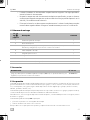
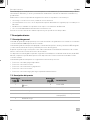
11 Troubleshooting . . . . . . . . . . . . . . . . . . . . . . . . . . . . . . . . . . . . . . . . . . . . . . . . . . . . . . . . . . . . . . . . . . . . . . . 19
12 Warranty. . . . . . . . . . . . . . . . . . . . . . . . . . . . . . . . . . . . . . . . . . . . . . . . . . . . . . . . . . . . . . . . . . . . . . . . . . . . . . 21
13 Disposal . . . . . . . . . . . . . . . . . . . . . . . . . . . . . . . . . . . . . . . . . . . . . . . . . . . . . . . . . . . . . . . . . . . . . . . . . . . . . . 21
14 Technical data . . . . . . . . . . . . . . . . . . . . . . . . . . . . . . . . . . . . . . . . . . . . . . . . . . . . . . . . . . . . . . . . . . . . . . . . . 21
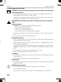
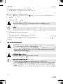
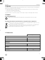
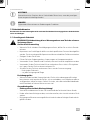
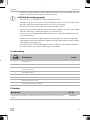
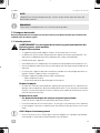
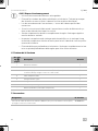
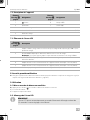
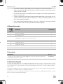
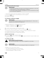
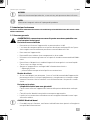
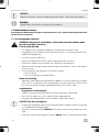
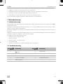
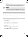
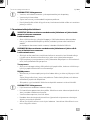
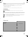
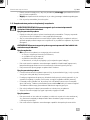
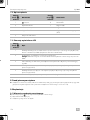
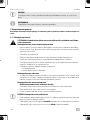
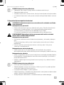
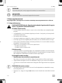
1 Explanation of symbols
D
!
!
DANGER!
Safety instruction: Indicates a hazardous situation that, if not avoided, will result in
death or serious injury.
WARNING!
Safety instruction: Indicates a hazardous situation that, if not avoided, could result in
death or serious injury.
CAUTION!
Safety instruction: Indicates a hazardous situation that, if not avoided, could result in
minor or moderate injury.

Safety instructions PJS1000
EN
10
A
I
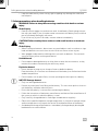
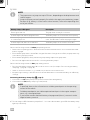
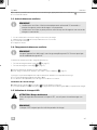
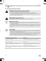
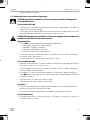
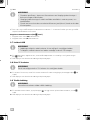
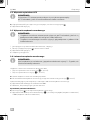
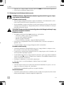
2 Safety instructions
Also observe the safety instructions and stipulations issued by the vehicle manufacturer and autho-
rized workshops.
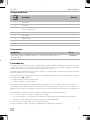
2.1 General safety
!WARNING! Failure to obey these warnings could result in death or serious
injury.
Electrocution hazard
• Do not operate the device if it is visibly damaged.
• The jump starter may only be repaired by qualified personnel. Improper repairs can
lead to considerable hazards.
• Do not disassemble the device.
• Do not modify or adapt any of the components in any way.
• Only use accessories and spare parts that are recommended by the manufacturer.
• Do not use the device in wet conditions or submerge in any liquid. Store in a dry
place.
• Switch off the device and disconnect it from the power supply:
– After every use
– Before each cleaning and maintenance
Risk of asphyxiation
• The cable and control unit of the device can give rise to risks of entanglement, stran-
gulation, tripping or treading if not correctly arranged. Ensure that excess ties and
power cables shall be arranged in a safe way.
Health hazard
•Electrical devices are not toys.
Always keep and use the device out of the reach of very young children.
• Children must be supervised to ensure that they do not play with the device.
• Cleaning and user maintenance shall not be made by children without supervision.
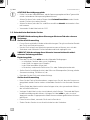
ANOTICE! Damage hazard
• Before start-up, check that the voltage specification on the data plate is the same as
that of the power supply.
•Ensure that other objects cannot cause a short circuit at the contacts of the device.
• Ensure that the negative and positive poles never come into contact.
• Do not use the cables as a handle.
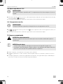
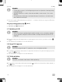
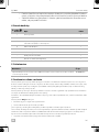
NOTICE!
Indicates a situation that, if not avoided, can result in property damage.
NOTE
Supplementary information for operating the product.

PJS1000 Safety instructions
EN
11
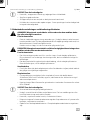
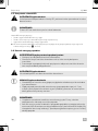
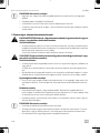
2.2 Operating the device safely
DDANGER! Failure to obey these warnings will result in death or serious injury.
Electrocution hazard
• Do not touch exposed cables with your bare hands. This applies especially when
operating the device from the AC power supply.
• To be able to disconnect the device quickly from the AC power supply, the socket
must be close to the device and be easily accessible.
!CAUTION! Failure to obey these cautions could result in minor or moderate
injury.
Explosion hazard
•Do not operate the device under the following conditions:
– In salty, wet or damp environments
– In the vicinity of corrosive fumes
– In the vicinity of combustible materials
– In areas where there is a risk of gas or dust explosion
• Do not place the jump starter near heat sources (heaters, direct sunlight, gas ovens,
etc.).
• Do not leave the device unattended when in use.
Electrocution hazard
• Before starting the device, ensure that the power supply cable and the plug are dry
and the plug is free from rust or dirt.
• When working on electrical systems, ensure that there is somebody close at hand
who can help in emergencies.
• Lay the cables so that they cannot be damaged by sharp edges, doors or the hood.
Do not lay any cable so that it is heavily kinked. Crushed cables can lead to serious
injury.
• Do not disconnect any cables when the device is still in use.
• Never pull the plug out of the socket by the cable.
Fire hazard
• Do not drop, hit or apply excessive force to the device to avoid damage to external
and internal parts.
• Do not place the jump starter near flammable materials.
Risk of injury
• When positioning the device, ensure that all cables are suitably secured to avoid any
form of trip hazard.
ANOTICE! Damage hazard
• Ensure that the air inlets and outlets of the device are not covered.
• Ensure a good ventilation.
• Set up the device in a dry location where it is protected against splashing water.

Safety precautions when handling batteries PJS1000
EN
12
• Loop the cable loosely when storing, tight wrapping may damage the cable and
internal parts.
3 Safety precautions when handling batteries
!WARNING! Failure to obey these warnings could result in death or serious
injury.
Risk of injury
• Batteries contain aggressive and caustic acids. Avoid battery fluid coming into con-
tact with your body. If your skin does come into contact with battery fluid, wash that
part of your body thoroughly with water.
If you sustain any injuries from acids, contact a doctor immediately.
!CAUTION! Failure to obey these cautions could result in minor or moderate
injury.
Risk of injury
• When working on batteries, do not wear any metal objects such as watches or rings.
Lead acid batteries can cause short circuits which can cause serious injuries.
• Wear goggles and protective clothing when you work on batteries. Do not touch
your eyes when you are working on batteries.
Health hazard
• Do not open or damage batteries or allow them to enter the environment, as they
contain toxic and environmentally harmful heavy metals.
Explosion hazard
• Never attempt to jump-start or charge a frozen or defective battery.
Place the battery in a frost-free area and wait until the battery has acclimatised to the
ambient temperature.
• Do not smoke, use an open flame, or cause sparking near the engine or a battery.
ANOTICE! Damage hazard
• Only use rechargeable batteries.
• Prevent any metal parts from falling on the battery. This can cause sparks or short-cir-
cuit the battery and other electrical parts.
• Ensure that the polarity is correct when connecting the battery.
• Follow the instructions of the battery manufacturer and those of the manufacturer of
the system or vehicle in which the battery is used.
• Only store fully charged batteries. Recharge stored batteries regularly.
• Observe the specified optimum storage temperature, as long-term storage at high
and low temperatures can impair the service life and performance of the battery.
• Avoid deep discharge of the batteries. Immediately recharge deeply discharged
lead batteries to avoid sulfation.

PJS1000 Scope of delivery
EN
13
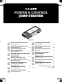
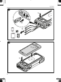
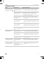
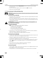
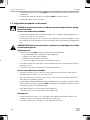
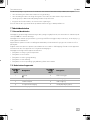
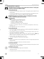
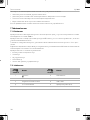
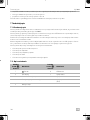
4 Scope of delivery
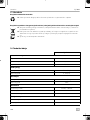
5 Accessories
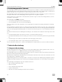
6 Intended use
The jump starter is intended to be used for bridging vehicles with 12 V batteries and up to 6 liter gasoline engines
or 4 liter diesel engines (e.g., cars, trucks, motorcycles, boats, lawn mowers, etc.) and for charging or operating
digital mobile devices (e.g., cell phones, tablets, laptops, cameras, etc.).
The jump starter is intended for temporarily use outdoors or in garages and reasonable care should be exercised
when using this device in wet conditions.
Other functions such as charging devices by ports are suitable for use at home, household workshops or garages.
The jump starter is not suitable for:
• Parallel connection with other jump starters
• Service workshops or commercial use
This product is only suitable for the intended purpose and application in accordance with these instructions.
This manual provides information that is necessary for proper installation and/or operation of the product. Poor
installation and/or improper operating or maintenance will result in unsatisfactory performance and a possible fail-
ure.
The manufacturer accepts no liability for any injury or damage to the product resulting from:
• Incorrect assembly or connection, including excess voltage
• Incorrect maintenance or use of spare parts other than original spare parts provided by the manufacturer
• Alterations to the product without express permission from the manufacturer
• Use for purposes other than those described in this manual
Dometic reserves the right to change product appearance and product specifications.
No. in
fig. 1,
page 3
Description Quantity
1 Jump starter 1
2 Carry bag 1
3 Jump-starting cable set (160 mm) with battery clamps and plug (EC5) with
short circuit protection
1
4 USB adapter cable 1
5 Car charger 1
6 Mains charger 1
– Short operating manual 1
– Operating manual (digital only) 1
Designation Ref. no.
Jump-starting cable set (300 mm) with battery clamps and plug (EC5) with short
circuit protection
9620006682

Technical description PJS1000
EN
14
7 Technical description
7.1 General description
The jump starter allows vehicles to be started without further assistance from third parties if a maximum peak current
of 1000 A is required to start the vehicle.
The jump starter is equipped with a lithium polymer battery and an integrated LED flashlight with continuous light,
strobe light and SOS signal for emergency situations.
With the two charging cables supplied, the device can be charged via the AC power supply or mobile via a 12 V
vehicle socket.
Digital mobile devices can be charged either by wireless or by one of the two USB outputs. In addition, the device
can be used to operate 12 V devices via the 12 V DC output.
The jump starter has the following protective mechanisms:
• High and low temperature protection
• Over current protection
• Low and over voltage protection
• Protection against short circuit
• Overcharge and deep discharge protection of the internal battery
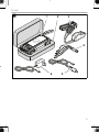
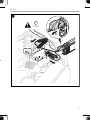
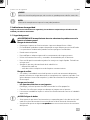
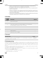
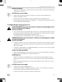
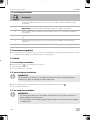
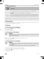
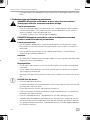
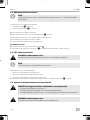
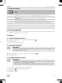
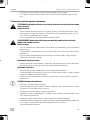
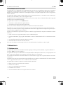
7.2 Description of the device
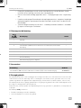
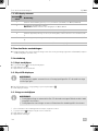
7.3 LCD display elements
Item in
fig. 2,
page 4
Designation
Item in
fig. 2,
page 4
Designation
1button 6 LED flashlight
2 LCD display 7 USB 1 output
3 Wireless charging pad 8 USB 2 output
4 12 V DC output 9 Jump-starting output (EC5)
5 Charging input
Item in
fig. 3,
page 4
Description
1 Indicates the current state of charge in percent between 0 % (discharged) and 100 % (fully
charged)
2 IN: Indicates that the jump starter is being charged.
Note: The indicator flashes until the jump starter is 100 % charged.
3 OUT: Indicates that a device is being charged or a vehicle is being jump started.
4 Indicates the measured voltage and current of the digital mobile device connected (USB 1).
5 Indicates the measured voltage and current of the digital mobile device connected (USB 2).
6 16 V: Indicates that a 12 V device is connected (12 V DC output).

PJS1000 Before first use
EN
15
8 Before first use
➤Charge the jump starter before first use or after long storage until it is fully charged (see chapter “Charging the
jump starter” on page 15).
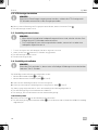
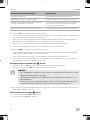
9 Operation
9.1 Switching the jump starter on
➤Press the button to switch the jump starter on.
✔The LCD display switches on.
✔The device is ready for use.
9.2 Switching the LCD display on
I
➤When the LCD display is in power saving mode, press the button briefly.
✔The LCD display switches on.
9.3 Switching the jump starter off
I
1. If connected, disconnect the loads or the charging source.
2. Press and hold the button for at least 5 seconds.
✔The LCD display switches off.
✔The device is switched off.
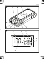
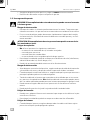
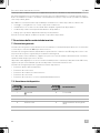
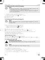
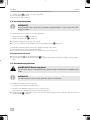
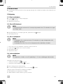
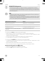
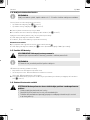
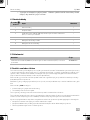
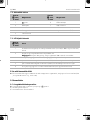
9.4 Charging the jump starter
I
The jump starter can be charged in two methods:
• Using the car charger (fig. 4A, page 5).
• Using the mains charger (fig. 4B, page 5).
➤Place the jump starter on a firm base.
➤To charge the jump starter proceed as shown (fig. 4, page 5).
NOTE
The LCD display automatically switches to the power saving mode after 20 seconds if
no settings are made.
NOTE
• The jump starter automatically switches off after 20 seconds if no load and no
charging source are connected.
• The jump starter cannot be switched off when a load or charging source is
connected.
NOTE
When the device is discharged, a full charge takes 3 – 5 hours with either charging
method.

Operation PJS1000
EN
16
Charging stops automatically when the jump starter is fully charged:
✔The LCD display shows the state of charge as 100 %.
✔The “IN” indicator stops flashing and is displayed permanently.
Checking the state of charge
➤Press the button to switch the jump starter on.
✔The LCD display shows the state of charge (fig. 3B, page 4) between 0 % (discharged) and 100 % (fully
charged).
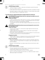
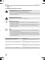
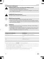
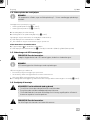
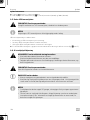
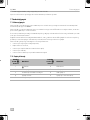
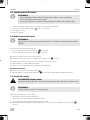
9.5 Using the LED flashlight
!
I
The LED flashlight offers three operating modes:
• Continuous light: The LED flashlight lights up continuously.
• Strobe light: The LED flashlight is flashing at a constant interval.
• SOS signal: The LED flashlight is flashing the SOS signal pattern.
➤To use the LED flashlight and switch between the different operating modes, proceed as shown (fig. 5,
page 5).
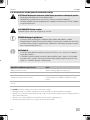
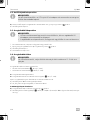
9.6 Jump-starting vehicles
!
!
A
CAUTION! Risk of injury
Avoid looking directly into the LED flashlight as this may damage your eyes.
NOTE
The operation of the LED flashlight is not available during charging.
WARNING! Electrocution hazard and fire hazard
• Do not connect the two battery clamps together.
• Do not use battery clamps other than those provided.
• Observe both the required connection and disconnection sequence of the battery
clamps and the correct polarity.
CAUTION! Risk of injury
Do not put fingers or hands into the battery clamps.
NOTICE! Damage hazard
• Do not jump-start a deeply discharged or defective vehicle battery.
• Do not attempt to jump start the vehicle more than 3 times in a row. If the vehicle
does not start after 3 attempts, the vehicle should be checked by authorized work-
shops.

PJS1000 Operation
EN
17
I
Observe the following instructions before jump-starting vehicles:
• Put the vehicle in parking position. Ensure that vehicles with manual transmission are in neutral and the hand-
brake is engaged.
• Ensure that the jump starter is at least 50 % charged. If the state of charge is below 50 %, the jump starter may
not be able to jump start a vehicle.
• Ensure that the plug (EC5) is firmly seated in the jump-starting output on the jump starter.
• Disconnect all digital mobile devices before connecting the battery clamps.
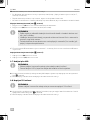
Observe the following instructions after jump-starting vehicles:
• Disconnect the battery clamps within 30 seconds in reverse order (see chapter “Disconnecting the battery
clamps (fig. 7, page 9)” on page 18).
• Switch on electrical consumers, e.g., ventilation to protect the on-board electronics.
• Keep the engine running or drive the vehicle for at least 30 minutes to ensure that the battery can sufficiently
recharge.
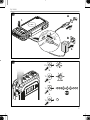
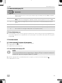
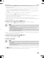
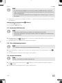
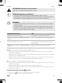
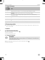
Connecting the battery clamps (fig. 6, page 6)
1. Connect the red (rd) battery clamp to the positive terminal of the starting battery.
2. Connect the black (bk) battery clamp to ground (chassis).
I
✔The red and green LED of the battery clamps flash 1 – 3 seconds. Afterwards the green LED of the battery clamp
lights up continuously.
NOTE
• The jump starter can jump-start up to 30 times, depending on the displacement and
vehicle engine.
• Jump-starting may not work properly for vehicles that require remote battery jumper
locations (e.g., battery is in the trunk or other location). Refer to the operating man-
ual of your vehicle.
Battery clamps’ LED signal Description
Flashes green and red The jump starter is ready for connection.
Continuously lit red, with beeping alarm tone The battery clamps are connected in reverse polarity.
Continuously lit green for 30 seconds, then changes
to continuously lit red
Disconnect the battery clamps and reconnect them to
reuse. The LED will be continuously lit green again.
Continuously lit red, with low constant tone The battery clamps are in contact to each other.
NOTE
• If specified, observe the information on suitable ground points in the operating
manual of the vehicle.
• Suitable ground points are stable unpainted metal parts in the engine compart-
ment, e.g., the engine block.
• If you cannot connect the black battery clamp ground (chassis), connect it to the
negative battery terminal.

Operation PJS1000
EN
18
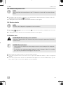
Disconnecting the battery clamps (fig. 7, page 7)
1. Disconnect the black (bk) battery clamp.
2. Disconnect the red (rd) battery clamp.
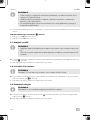
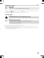
9.7 Charging via USB
I
➤To charge digital mobile devices, use the USB adapter cable provided and proceed as shown (fig. 8, page 8).
✔The LCD display shows the remaining state of charge of the jump starter.
9.8 Operating 12 V devices
I
➤To operate 12 V devices, connect the power cable of the 12 V device to the 12 V DC output of the jump starter
(fig. 24, page 4).
✔The LCD display shows the remaining state of charge of the jump starter.
9.9 Wireless charging
I
➤To wireless charge devices, press the button and place the device on the wireless charging pad, see fig. 9,
page 8.
➤The LCD display shows the remaining state of charge of the jump starter.
NOTE
• Charging of digital mobile devices is not possible while the jump starter is being
charged.
• Two digital mobile devices can be charged at the same time by using both USB out-
puts.
NOTE
Operation of 12 V devices is not possible while the jump starter is being charged.
NOTE
Ensure the device supports wireless charging.

PJS1000 Cleaning and maintenance
EN
19
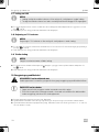
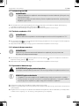
10 Cleaning and maintenance
!
A
➤Occasionally clean the device with a soft, damp cloth.
➤Regularly check live cables or lines for insulation faults, breaks or loose connections.
➤Regularly check the state of charge of the device battery. Charge the battery after each use and at least every
3–6months, even when not in use.
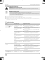
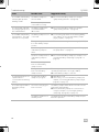
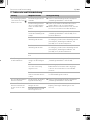
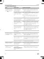
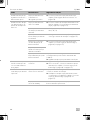
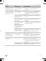
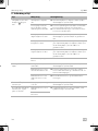
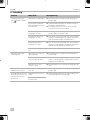
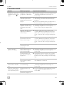
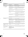
11 Troubleshooting
WARNING! Electrocution hazard
Unplug the device from the power supply before each cleaning and maintenance.
NOTICE! Damage hazard
• Never clean the device under running water or in dish water.
• Do not use sharp or hard objects, abrasive cleaning agents or bleach during clean-
ing as these can damage the device.
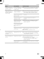
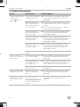
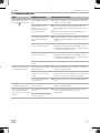
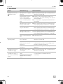
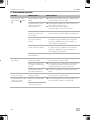
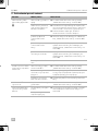
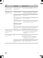
Fault Possible cause Suggested remedy
The jump starter does not
work. The button
does not work.
The jump starter is deeply
discharged.
➤Charge the jump starter (see chapter “Charging
the jump starter” on page 15).
Insulation faults, breaks or
loose connections at the
live cables.
➤Check live cables for insulation faults, breaks or
loose connections.
➤If you cannot find an error, contact an authorized
service agent.
The low voltage protection
of the jump starter is
active.
➤Charge the jump starter (see chapter “Charging
the jump starter” on page 15) to reactivate it.
The over current protec-
tion of the jump starter is
active.
➤Remove the load from the USB or 12 V DC output.
Charge the jump starter (see chapter “Charging
the jump starter” on page 15) to reactivate it.
The short circuit protection
of the jump starter is
active.
➤Remove the load from the USB or 12 V DC output.
Charge the jump starter (see chapter “Charging
the jump starter” on page 15) to reactivate it.
The battery is significantly
sulfated.
➤Replace the battery.
The vehicle is not jump-
started.
The jump starter is less
than 50 % charged.
➤Charge the jump starter (see chapter “Charging
the jump starter” on page 15).
The battery clamps are
loose or not connected
correctly.
➤Check the connections. Ensure that the battery
clamps are firmly secured and connected cor-
rectly. Reconnect if necessary.
The battery terminals are
dirty or corroded.
➤Clean the battery terminals and reconnect the
jump starter.
The red LED of the battery
clamps lights up.
The jump starter voltage is
too low.
➤Charge the jump starter (see chapter “Charging
the jump starter” on page 15).

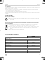
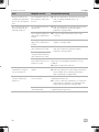
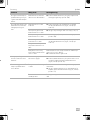
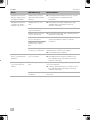
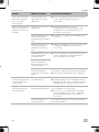
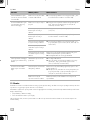
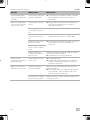
Troubleshooting PJS1000
EN
20
The red LED of the battery
clamps lights up and a
buzzing sounds.
The battery clamps are
short circuited.
➤Reconnect the battery clamps (see chapter
“Jump-starting vehicles” on page 16).
The battery clamps are
connected incorrectly.
The green LED of the bat-
tery clamps lights up and
the red LED flashes.
The battery clamps have
not activated within
30 seconds.
➤Reconnect the battery clamps (see chapter
“Jump-starting vehicles” on page 16).
The red LED of the battery
clamps flashes. The jump
starter does not operate.
The battery clamps are not
connected.
➤Connect the jump starter to the starting battery
(see chapter “Connecting the battery clamps
(fig. 6, page 8)” on page 17).
The high voltage protec-
tion of the battery clamps
is active.
➤Ensure that the voltage is not too high (> 16.7 V).
The low voltage protection
of the battery clamps is
active.
➤Charge the jump starter (see chapter “Charging
the jump starter” on page 15).
The short circuit protection
of the battery clamps is
active.
➤Reconnect the battery clamps (see chapter “Con-
necting the battery clamps (fig. 6, page 8)” on
page 17).
The reverse polarity pro-
tections of the battery
clamps is active.
The high temperature pro-
tection of the battery
clamps is active.
The battery clamps switch off automatically when the
operating temperature is too high (> 80°C).
➤Let the battery clamps cool down.
The jump starterdoes not
operate after it is
connected to the starting
battery.
The start of the battery
clamps is in progress.
➤Wait 30 seconds.
➤If necessary, reconnect the battery clamps (see
chapter “Connecting the battery clamps (fig. 6,
page 8)” on page 17).
The red and green LED of
the battery clamps
flashes.
The reverse charging pro-
tection is active.
The battery clamps switch off the connection to the
jump starter automatically.
➤Ensure the battery clamps are connected cor-
rectly (see chapter “Connecting the battery
clamps (fig. 6, page 8)” on page 17).
The battery clamps are in
stand-by mode.
The flashing stops when the battery clamps are put
back into operation.
Fault Possible cause Suggested remedy
A página está carregando...
A página está carregando...
A página está carregando...
A página está carregando...
A página está carregando...
A página está carregando...
A página está carregando...
A página está carregando...
A página está carregando...
A página está carregando...
A página está carregando...
A página está carregando...
A página está carregando...
A página está carregando...
A página está carregando...
A página está carregando...
A página está carregando...
A página está carregando...
A página está carregando...
A página está carregando...
A página está carregando...
A página está carregando...
A página está carregando...
A página está carregando...
A página está carregando...
A página está carregando...
A página está carregando...
A página está carregando...
A página está carregando...
A página está carregando...
A página está carregando...
A página está carregando...
A página está carregando...
A página está carregando...
A página está carregando...
A página está carregando...
A página está carregando...
A página está carregando...
A página está carregando...
A página está carregando...
A página está carregando...
A página está carregando...
A página está carregando...
A página está carregando...
A página está carregando...
A página está carregando...
A página está carregando...
A página está carregando...
A página está carregando...
A página está carregando...
A página está carregando...
A página está carregando...
A página está carregando...
A página está carregando...
A página está carregando...
A página está carregando...
A página está carregando...
A página está carregando...
A página está carregando...
A página está carregando...
A página está carregando...
A página está carregando...
A página está carregando...
A página está carregando...
A página está carregando...
A página está carregando...
A página está carregando...
A página está carregando...
A página está carregando...
A página está carregando...
A página está carregando...
A página está carregando...
A página está carregando...
A página está carregando...
A página está carregando...
A página está carregando...
A página está carregando...
A página está carregando...
A página está carregando...
A página está carregando...
A página está carregando...
A página está carregando...
A página está carregando...
A página está carregando...
A página está carregando...
A página está carregando...
A página está carregando...
A página está carregando...
A página está carregando...
A página está carregando...
A página está carregando...
A página está carregando...
A página está carregando...
A página está carregando...
A página está carregando...
A página está carregando...
A página está carregando...
A página está carregando...
A página está carregando...
A página está carregando...
A página está carregando...
A página está carregando...
A página está carregando...
A página está carregando...
A página está carregando...
A página está carregando...
A página está carregando...
A página está carregando...
A página está carregando...
A página está carregando...
A página está carregando...
A página está carregando...
A página está carregando...
A página está carregando...
A página está carregando...
A página está carregando...
A página está carregando...
A página está carregando...
A página está carregando...
A página está carregando...
A página está carregando...
A página está carregando...
A página está carregando...
A página está carregando...
A página está carregando...
A página está carregando...
A página está carregando...
A página está carregando...
A página está carregando...
A página está carregando...
A página está carregando...
A página está carregando...
A página está carregando...
A página está carregando...
A página está carregando...
A página está carregando...
A página está carregando...
A página está carregando...
A página está carregando...
A página está carregando...
A página está carregando...
A página está carregando...
A página está carregando...
A página está carregando...
A página está carregando...
A página está carregando...
A página está carregando...
A página está carregando...
A página está carregando...
A página está carregando...
A página está carregando...
A página está carregando...
A página está carregando...
A página está carregando...
A página está carregando...
A página está carregando...
A página está carregando...
A página está carregando...
A página está carregando...
A página está carregando...
A página está carregando...
A página está carregando...
A página está carregando...
A página está carregando...
A página está carregando...
A página está carregando...
A página está carregando...
A página está carregando...
A página está carregando...
A página está carregando...
A página está carregando...
A página está carregando...
A página está carregando...
A página está carregando...
A página está carregando...
A página está carregando...
A página está carregando...
A página está carregando...
A página está carregando...
A página está carregando...
A página está carregando...
A página está carregando...
A página está carregando...
A página está carregando...
A página está carregando...
A página está carregando...
A página está carregando...
A página está carregando...
A página está carregando...
A página está carregando...
A página está carregando...
A página está carregando...
A página está carregando...
A página está carregando...
A página está carregando...
A página está carregando...
A página está carregando...
A página está carregando...
A página está carregando...
A página está carregando...
A página está carregando...
A página está carregando...
A página está carregando...
A página está carregando...
A página está carregando...
A página está carregando...
A página está carregando...
A página está carregando...
A página está carregando...
A página está carregando...
A página está carregando...
A página está carregando...
A página está carregando...
A página está carregando...
A página está carregando...
A página está carregando...
A página está carregando...
A página está carregando...
A página está carregando...
A página está carregando...
A página está carregando...
A página está carregando...
A página está carregando...
A página está carregando...
A página está carregando...
A página está carregando...
A página está carregando...
A página está carregando...
-
 1
1
-
 2
2
-
 3
3
-
 4
4
-
 5
5
-
 6
6
-
 7
7
-
 8
8
-
 9
9
-
 10
10
-
 11
11
-
 12
12
-
 13
13
-
 14
14
-
 15
15
-
 16
16
-
 17
17
-
 18
18
-
 19
19
-
 20
20
-
 21
21
-
 22
22
-
 23
23
-
 24
24
-
 25
25
-
 26
26
-
 27
27
-
 28
28
-
 29
29
-
 30
30
-
 31
31
-
 32
32
-
 33
33
-
 34
34
-
 35
35
-
 36
36
-
 37
37
-
 38
38
-
 39
39
-
 40
40
-
 41
41
-
 42
42
-
 43
43
-
 44
44
-
 45
45
-
 46
46
-
 47
47
-
 48
48
-
 49
49
-
 50
50
-
 51
51
-
 52
52
-
 53
53
-
 54
54
-
 55
55
-
 56
56
-
 57
57
-
 58
58
-
 59
59
-
 60
60
-
 61
61
-
 62
62
-
 63
63
-
 64
64
-
 65
65
-
 66
66
-
 67
67
-
 68
68
-
 69
69
-
 70
70
-
 71
71
-
 72
72
-
 73
73
-
 74
74
-
 75
75
-
 76
76
-
 77
77
-
 78
78
-
 79
79
-
 80
80
-
 81
81
-
 82
82
-
 83
83
-
 84
84
-
 85
85
-
 86
86
-
 87
87
-
 88
88
-
 89
89
-
 90
90
-
 91
91
-
 92
92
-
 93
93
-
 94
94
-
 95
95
-
 96
96
-
 97
97
-
 98
98
-
 99
99
-
 100
100
-
 101
101
-
 102
102
-
 103
103
-
 104
104
-
 105
105
-
 106
106
-
 107
107
-
 108
108
-
 109
109
-
 110
110
-
 111
111
-
 112
112
-
 113
113
-
 114
114
-
 115
115
-
 116
116
-
 117
117
-
 118
118
-
 119
119
-
 120
120
-
 121
121
-
 122
122
-
 123
123
-
 124
124
-
 125
125
-
 126
126
-
 127
127
-
 128
128
-
 129
129
-
 130
130
-
 131
131
-
 132
132
-
 133
133
-
 134
134
-
 135
135
-
 136
136
-
 137
137
-
 138
138
-
 139
139
-
 140
140
-
 141
141
-
 142
142
-
 143
143
-
 144
144
-
 145
145
-
 146
146
-
 147
147
-
 148
148
-
 149
149
-
 150
150
-
 151
151
-
 152
152
-
 153
153
-
 154
154
-
 155
155
-
 156
156
-
 157
157
-
 158
158
-
 159
159
-
 160
160
-
 161
161
-
 162
162
-
 163
163
-
 164
164
-
 165
165
-
 166
166
-
 167
167
-
 168
168
-
 169
169
-
 170
170
-
 171
171
-
 172
172
-
 173
173
-
 174
174
-
 175
175
-
 176
176
-
 177
177
-
 178
178
-
 179
179
-
 180
180
-
 181
181
-
 182
182
-
 183
183
-
 184
184
-
 185
185
-
 186
186
-
 187
187
-
 188
188
-
 189
189
-
 190
190
-
 191
191
-
 192
192
-
 193
193
-
 194
194
-
 195
195
-
 196
196
-
 197
197
-
 198
198
-
 199
199
-
 200
200
-
 201
201
-
 202
202
-
 203
203
-
 204
204
-
 205
205
-
 206
206
-
 207
207
-
 208
208
-
 209
209
-
 210
210
-
 211
211
-
 212
212
-
 213
213
-
 214
214
-
 215
215
-
 216
216
-
 217
217
-
 218
218
-
 219
219
-
 220
220
-
 221
221
-
 222
222
-
 223
223
-
 224
224
-
 225
225
-
 226
226
-
 227
227
-
 228
228
-
 229
229
-
 230
230
-
 231
231
-
 232
232
-
 233
233
-
 234
234
-
 235
235
-
 236
236
-
 237
237
-
 238
238
-
 239
239
-
 240
240
-
 241
241
-
 242
242
-
 243
243
-
 244
244
-
 245
245
-
 246
246
-
 247
247
-
 248
248


em outras línguas
- français: Dometic PJS1000 Mode d'emploi
- italiano: Dometic PJS1000 Istruzioni per l'uso
- Nederlands: Dometic PJS1000 Handleiding
- slovenčina: Dometic PJS1000 Návod na používanie
- Deutsch: Dometic PJS1000 Bedienungsanleitung
- dansk: Dometic PJS1000 Betjeningsvejledning
- svenska: Dometic PJS1000 Bruksanvisningar
Artigos relacionados
Outros documentos
-
Denver JST-10010 Manual do usuário
-
ULTIMATE SPEED UPBS 12000 A1 Operation and Safety Notes
-
Schumacher FR01241FR01241 Manual do proprietário
-
Schumacher SL1391U Lithium Ion Tactical Jump Starter Light SL1398U Lithium Ion Tactical Jump Starter Light SL1399U Lithium Ion Tactical Jump Starter Light Manual do proprietário
-
ULTIMATE SPEED ULG 12 A2 Operation and Safety Notes
-
Perel AJUS7 Manual do usuário
-
Denver JST-9200 Waterproof IP66 Jump Starter Manual do usuário
-
Promate Patrol-2 Guia de usuario
-
NOCO GB40 Boost Plus 1000A Jump Starter Manual do usuário
-
 Ring Powering SmartChargePro25 Quick Start Manuals
