
CD-WAx-00-2 Series
Wall Mount CO
2
Transmitters
Installation Instructions
CD-WA0-00-2, CD-WAD-00-2
Part No. 24-10863-9 Rev. B
Issued April 8, 2016
Deutsch
Português
中文
English
Français
Italiano
Español
Nederlands
Čeština
Svenska
Polski
Русский

European Single Point of Contact:
JOHNSON CONTROLS
WESTENDHOF 3
45143 ESSEN
GERMANY
NA/SA Single Point of Contact:
JOHNSON CONTROLS
507 E MICHIGAN ST
MILWAUKEE WI 53202
USA
APAC Single Point of Contact:
JOHNSON CONTROLS
C/O CONTROLS PRODUCT MANAGEMENT
NO. 22 BLOCK D NEW DISTRICT
WUXI JIANGSU PROVINCE 214142
CHINA

1
ENGLISH
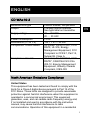
CD-WAx-00-2
Measurement type
Carbon dioxide, temperature
Output
2 analog output channels
See type label on transmitter
Supply voltage
18 ... 35 VDC
20 … 30 VAC
Power consumption
< 2 W
Dimensions (h × w × d)
132.7 × 81 × 30 mm
Compliance: United States
UL Listed, File E107041, CCN
PAZX, UL 916, Energy
Management Equipment, FCC
Compliant to CFR 47, Part 15,
Subpart B, Class A
Compliance: Canada
UL Listed, File E107041, CCN
PAZX7, CAN/CSA C22.2 No.
205-12, Energy Management
Equipment, Industry Canada
Compliant, ICES-003
North American Emissions Compliance
United States
This equipment has been tested and found to comply with the
limits for a Class A digital device pursuant to Part 15 of the
FCC Rules. These limits are designed to provide reasonable
protection against harmful interference when this equipment is
operated in a commercial environment. This equipment
generates, uses, and can radiate radio frequency energy and,
if not installed and used in accordance with the instruction
manual, may cause harmful interference to radio
communications. Operation of this equipment in a residential
EN

2
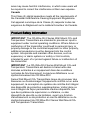
area may cause harmful interference, in which case users will
be required to correct the interference at their own expense.
Canada
This Class (A) digital apparatus meets all the requirements of
the Canadian Interference-Causing Equipment Regulations.
Cet appareil numérique de la Classe (A) respecte toutes les
exigences du Règlement sur le matériel brouilleur du Canada.
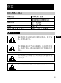
Product Safety Information
IMPORTANT: The CD-WAx-00-2 Series Wall Mount CO
2
and
Temperature Transmitters are intended to provide an input to
equipment under normal operating conditions. Where failure or
malfunction of the transmitter could lead to personal injury or
property damage to the controlled equipment or other property,
additional precautions must be designed into the control
system. Incorporate and maintain other devices, such as
supervisory or alarm systems or safety or limit controls,
intended to warn of or protect against failure or malfunction of
the transmitter.
IMPORTANT : Le CD-WAx-00-2 Series Wall Mount CO
2
and
Temperature Transmitters est destiné à transmettre des
données entrantes à un équipement dans des conditions
normales de fonctionnement. Lorsqu'une défaillance ou un
dysfonctionnement du CD-WAx-00-2
Series Wall Mount CO
2
Transmitters risque de provoquer des
blessures ou d'endommager l'équipement contrôlé ou un autre
équipement, la conception du système de contrôle doit intégrer
des dispositifs de protection supplémentaires. Veiller dans ce
cas à intégrer de façon permanente d'autres dispositifs, tels
que des systèmes de supervision ou d'alarme, ou des
dispositifs de sécurité ou de limitation, ayant une fonction
d'avertissement ou de protection en cas de défaillance ou de
dysfonctionnement du CD-WAx-00-2 Series Wall Mount CO
2
and Temperature Transmitters.

3
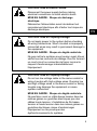
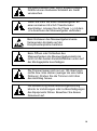
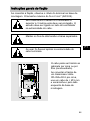
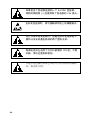
CAUTION: Risk of Electric Shock.
Disconnect the power supply before making
electrical connections to avoid electric shock.
MISE EN GARDE : Risque de décharge
électrique.
Débrancher l'alimentation avant de réaliser tout
raccordement électrique afin d'éviter tout risque de
décharge électrique.
CAUTION: Risk of Property Damage.
Do not apply power to the system before checking
all wiring connections. Short circuited or improperly
connected wires may result in permanent damage to
the equipment.
MISE EN GARDE : Risque de dégâts matériels.
Ne pas mettre le système sous tension avant d'avoir
vérifié tous les raccords de câblage. Des fils formant
un court-circuit ou connectés de façon incorrecte
risquent d'endommager irrémédiablement
l'équipement.
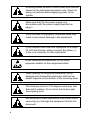
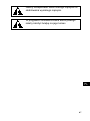
CAUTION: Risk of Property Damage.
Do not run low voltage cable in the same conduit or
wiring troughs with high voltage wires. Running low
and high voltage wires in the same conduit or wiring
troughs may damage the equipment or cause
system malfunction.
MISE EN GARDE : Risque de dégâts matériels.
Ne pas faire courir un câble basse tension dans les
mêmes gaines ou goulottes électriques que des
câbles haute tension. L'installation de fils basse
tension et haute tension dans les mêmes gaines ou
goulottes électriques risque d'endommager
l'équipement ou de provoquer des
dysfonctionnements du système.
EN

4
All w
iring should conform to local codes and must be
carried out by authorized personnel only. Check all
wiring connections before applying power to the
system.
Make
sure that the line power supply is in
accordance with the power supply specified on
page 1.
Short-circuited or improperly connected wires may
result in permanent damage to the equipment.
If you
connect more than one transmitter to a single
24 VAC transformer, always connect the phase (~)
to the +Vs connector in each transmitter.
When ins
talling the transmitter, do not touch
exposed contacts on the component board.
When
opening or closing the transmitter, avoid
damaging the transmitter electronics with the two
plastic supports on the bottom of the mounting base.
The tr
immers only turn 135 degrees each way, less
than half a rotation. Do not force the trimmer past
the stopping point.
Not adhering to these operational instructions could
cause injury or damage the equipment. Retain this
document.

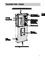
5
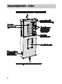
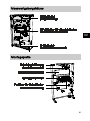
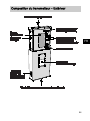
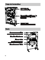
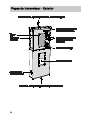
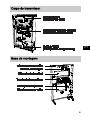
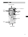
Transmitter Parts - Outside
EN

6
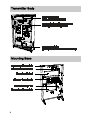
Transmitter Body
Mounting Base

7
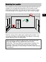
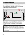
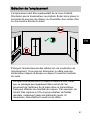
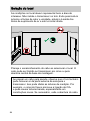
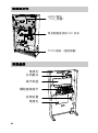
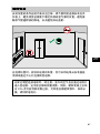
Selecting the Location
The conditions at the location should represent well the area of
interest. Do not install the transmitter on the ceiling. Avoid
placing the transmitter near heat and moisture sources, close
to the discharge of the supply air ducts, and in direct sunlight.
Plan the routing of the cable when selecting the location. You
can bring the cable to the transmitter from above, or from the
center opening of the mounting base.
When bringing a cable through the wall, note that the hole
may also supply air from outside the room into the
transmitter. This may affect the measurement readings. For
example, fresh concrete binds CO
2
and may cause low
readings, especially in new buildings. Seal the cable opening
if necessary.
EN

8
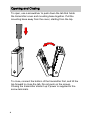
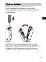
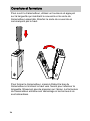
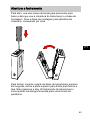
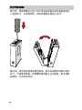
Opening and Closing
To open, use a screwdriver to push down the tab that holds
the transmitter cover and mounting base together. Pull the
mounting base away from the cover, starting from the top.
To cl
ose, connect the bottom of the transmitter first, and tilt the
top forward to close the tab. Do not push on the screen.
Closing the transmitter starts it up if power is supplied to the
screw terminals.

9
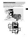
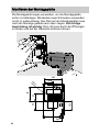
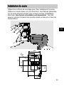
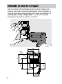
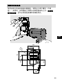
Installing the Mounting Base
Use the mounting holes to attach the mounting base securely.
Use at least two screws (not included). The arrow on the
mounting base must point straight up after installation.
Proper orientation is important: air must flow through the
vents on the bottom and top.
50
34
27
Ø 4.4
33.5
30.5
29.8
59.5
EN

10
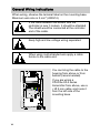
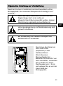
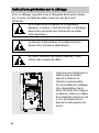
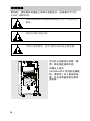
General Wiring Instructions
When wiring, observe the terminal label on the mounting base.
Maximum wire size is 2 mm
2
(AWG14).
If the cable between the sensor and the
controller is over 3 meters, it should be shielded.
The shield would be connected at the controller
end of the cable.
Keep high and low voltage wiring separated.
When using multi-stranded wire apply a cable
ferrule to the cable end.
You can bring the cable to the
housing from above or from
behind (recommended).
If you are wiring a
CD-WAx-00-2 series
transmitter from above, use a
< Ø 5 mm cable, and route it
from the left side of the
mounting base.

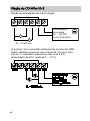
11
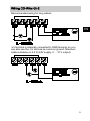
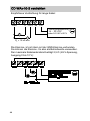
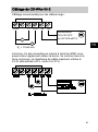
Wiring CD-WAx-00-2
Recommended wiring for long cables:
-Vs ter
minal is internally connected to GND terminal, so you
can also use the -Vs terminal as common ground. Maximum
cable resistance is 2.5 Ω (24V supply, 0 ... 10 V output):
EN

12
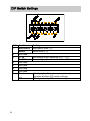
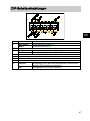
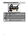
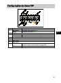
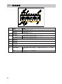
DIP Switch Settings
DIP
Position
Setting
1
Non-metric
Non-metric units (°F).
Metric
Metric units (°C).
2
Not used
3
0...5V
Set analog output channels to 0 ... 5 V
0...10V
Set analog output channels to 0 ... 10 V
4
Not used
5
Not used
6
Not used
7
Not used
8
Custom
Configuration through service port only.
Ignores all other DIP switch settings.
DIP
Configuration by DIP switches only.

13
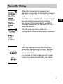
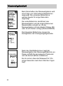
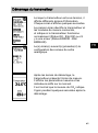
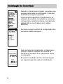
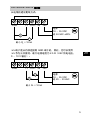
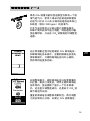
Transmitter Startup
When the transmitter is powered on, it
displays a sequence of information screens.
The screens are shown for a few seconds
each.
The first screen identifies the transmitter and
the connected measurement modules,
and shows if the transmitter is operating
normally (status OK) or if there is an error
(status ERROR).
The following screen(s) show the
configuration of the analog output channels.
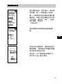
After the startup screens the transmitter
shows the measurement screen. It shows
the measured parameters and currently
active indicators.
It is normal for CO
2
measurement to read
0 ppm for a few seconds after the startup.
EN

14
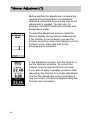
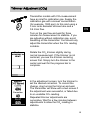
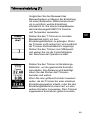
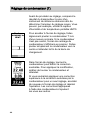
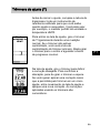
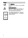
Trimmer Adjustment (T)
Before starting the adjustment, compare the
reading of the transmitter to a calibrated
reference instrument so you know how much
adjustment is needed. You can use, for
example, the HM70 hand-held humidity and
temperature meter.
To enter the adjustment screen, rotate the
trimmer slightly during normal measurement.
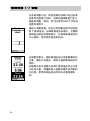
If the trimmer is not centered, you see the
trimmer centering screen first. Simply turn the
trimmer to the center and wait for the
progress bar to complete.
In the adjustment screen, turn the trimmer to
set the desired correction. To commit the
change, stop turning the trimmer and wait.
If you wish to apply a greater correction than
allowed by the trimmer in a single adjustment,
re-enter the adjustment screen and apply a
new correction. Corrections applied using the
trimmers are cumulative.

15
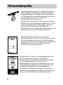
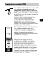
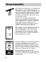
Trimmer Adjustment (CO
2
)
Transm
itter models with CO
2
measurement
have an inlet for calibration gas. Supply the
calibration gas with a known concentration
(for example, 1000 ppm) to this inlet using a
3 mm inner diameter silicone tube and a
0.4 l/min flow.
Turn on the gas flow and wait for three
minutes for measurement to stabilize. If you
are adjusting without calibration gas, avoid
breathing on the transmitter. You should only
adjust the transmitter when the CO
2
reading
is stable.
Rotate the CO
2
trimmer slightly during
normal measurement. If the trimmer is not
centered, you see the trimmer centering
screen first. Simply turn the trimmer to the
center and wait for the progress bar to
complete.
In the adjustment screen, turn the trimmer to
set the desired correction. To commit the
change, stop turning the trimmer and wait.
The transmitter will show with a text screen if
the adjustment was successful, or failed due
to an unstable CO
2
reading.
Repeated trimmer adjustments are
cumulative. Wait for a few minutes between
adjustments to allow the CO
2
reading to
stabilize.
EN

16
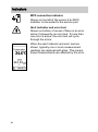
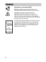
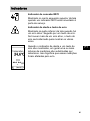
Indicators
MI70 connection indicator
Shown on top left of the screen if an MI70
Indicator is connected to the service port.
Alert indicator and error text
Shown on bottom of screen if there is an error
active. Followed by an error text. If more than
one error is active, the error text will cycle
through the errors.
When the alert indicator and error text are
shown, typically one or more measurement
readings are replaced with stars. This means
these measurements are affected by the error.

17
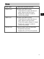
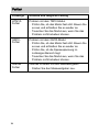
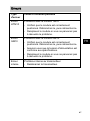
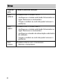
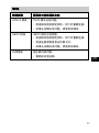
Errors
Error Type Cause and Possible Solution
HTM10 error Problem with TM10 module.
- Check that the module sits firmly in
place. Remove and reconnect.
- Replace the module if unable to
remove the problem.
GM10 error Problem with GM10 module.
- Check that the module sits firmly in
place. Remove and reconnect.
- Check that supply voltage is in range.
- Replace the module if unable to
remove the problem.
Internal error Internal problem with the transmitter.
- Restart the transmitter.
- Replace the unit if the error persists.
EN

18
DEUTSCH
CD-WAx-00-2
Art der Messung
Kohlendioxid, Temperatur
Ausgang
2 Analogausgangskanäle,
siehe Etikett auf dem
Messwertgeber
Speisespannung
18 ... 35 V DC
20 … 30 V AC
Stromverbrauch
< 2,0 W
Abmessungen (H × B × T)
132,7 × 81 × 30 mm
Produktsicherheitsinformationen
Der K
ontakt mit Komponenten, auf denen
gefährliche Spannung anliegt, kann zu einem
Stromschlag führen und schwere Körperschäden
oder sogar den Tod zur Folge haben.
Der el
ektrische Anschluß ist nach den örtlichen
Vorschriften durch autorisiertes Personal
durchzuführen. Überprüfen Sie alle
Kabelverbindungen bevor Sie den
Messwertgeber einschalten.
Stellen Sie sicher, dass die
Versorgungsspannung mit dem angegebenen
Wert auf Seite 18 übereinstimmt.
A página está carregando...
A página está carregando...
A página está carregando...
A página está carregando...
A página está carregando...
A página está carregando...
A página está carregando...
A página está carregando...
A página está carregando...
A página está carregando...
A página está carregando...
A página está carregando...
A página está carregando...
A página está carregando...
A página está carregando...
A página está carregando...
A página está carregando...
A página está carregando...
A página está carregando...
A página está carregando...
A página está carregando...
A página está carregando...
A página está carregando...
A página está carregando...
A página está carregando...
A página está carregando...
A página está carregando...
A página está carregando...
A página está carregando...
A página está carregando...
A página está carregando...
A página está carregando...
A página está carregando...
A página está carregando...
A página está carregando...
A página está carregando...
A página está carregando...
A página está carregando...
A página está carregando...
A página está carregando...
A página está carregando...
A página está carregando...
A página está carregando...
A página está carregando...
A página está carregando...
A página está carregando...
A página está carregando...
A página está carregando...
A página está carregando...
A página está carregando...
A página está carregando...
A página está carregando...
A página está carregando...
A página está carregando...
A página está carregando...
A página está carregando...
A página está carregando...
A página está carregando...
A página está carregando...
A página está carregando...
A página está carregando...
A página está carregando...
A página está carregando...
A página está carregando...
A página está carregando...
A página está carregando...
A página está carregando...
A página está carregando...
A página está carregando...
A página está carregando...
A página está carregando...
A página está carregando...
A página está carregando...
A página está carregando...
-
 1
1
-
 2
2
-
 3
3
-
 4
4
-
 5
5
-
 6
6
-
 7
7
-
 8
8
-
 9
9
-
 10
10
-
 11
11
-
 12
12
-
 13
13
-
 14
14
-
 15
15
-
 16
16
-
 17
17
-
 18
18
-
 19
19
-
 20
20
-
 21
21
-
 22
22
-
 23
23
-
 24
24
-
 25
25
-
 26
26
-
 27
27
-
 28
28
-
 29
29
-
 30
30
-
 31
31
-
 32
32
-
 33
33
-
 34
34
-
 35
35
-
 36
36
-
 37
37
-
 38
38
-
 39
39
-
 40
40
-
 41
41
-
 42
42
-
 43
43
-
 44
44
-
 45
45
-
 46
46
-
 47
47
-
 48
48
-
 49
49
-
 50
50
-
 51
51
-
 52
52
-
 53
53
-
 54
54
-
 55
55
-
 56
56
-
 57
57
-
 58
58
-
 59
59
-
 60
60
-
 61
61
-
 62
62
-
 63
63
-
 64
64
-
 65
65
-
 66
66
-
 67
67
-
 68
68
-
 69
69
-
 70
70
-
 71
71
-
 72
72
-
 73
73
-
 74
74
-
 75
75
-
 76
76
-
 77
77
-
 78
78
-
 79
79
-
 80
80
-
 81
81
-
 82
82
-
 83
83
-
 84
84
-
 85
85
-
 86
86
-
 87
87
-
 88
88
-
 89
89
-
 90
90
-
 91
91
-
 92
92
-
 93
93
-
 94
94


Johnson Controls CD-WA -00-2 Series Installation Instructions Manual
- Tipo
- Installation Instructions Manual
- Este manual também é adequado para
em outras línguas
- français: Johnson Controls CD-WA -00-2 Series
- English: Johnson Controls CD-WA -00-2 Series
- Deutsch: Johnson Controls CD-WA -00-2 Series
Outros documentos
-
Vaisala HMD65 Manual do usuário
-
-
-
Hama 00186434 Air Quality Detector Manual do proprietário
-
-
-
-
Mettler Toledo Transmitter M400 Instruções de operação
-
Chamberlain TPD500 Manual do proprietário
-