
EN
DE
FR
ES
PT
RU
JA
ZH
M212049EN-C
Quick Guide
HMD60 Series Humidity and Temperature
Transmitters for Ducts in HVAC
HMD62 TMD62

PUBLISHED BY
Vaisala Oyj
Vanha Nurmijärventie 21, FI-01670 Vantaa, Finland
P.O. Box 26, FI-00421 Helsinki, Finland
+358 9 8949 1
Visit our Internet pages at www.vaisala.com.
No part of this document may be
reproduced, published or publicly
displayed in any form or by any means,
electronic or mechanical (including
photocopying), nor may its contents be
modified, translated, adapted, sold or
disclosed to a third party without prior
written permission of the copyright holder.
Translated documents and translated
portions of multilingual documents are
based on the original English versions. In
ambiguous cases, the English versions are
applicable, not the translations.
The contents of this document are subject
to change without prior notice.
Local rules and regulations may vary and
they shall take precedence over the
information contained in this document.
Vaisala makes no representations on this
document’s compliance with the local
rules and regulations applicable at any
given time, and hereby disclaims any and
all responsibilities related thereto.
This document does not create any legally
binding obligations for Vaisala towards
customers or end users. All legally binding
obligations and agreements are included
exclusively in the applicable supply
contract or the General Conditions of Sale
and General Conditions of Service of
Vaisala.
This product contains software developed
by Vaisala or third parties. Use of the
software is governed by license terms and
conditions included in the applicable
supply contract or, in the absence of
separate license terms and conditions, by
the General License Conditions of Vaisala
Group.

Table of Contents
English.............................................................................................................................................5
Deutsch......................................................................................................................................... 17
Français........................................................................................................................................29
Español.........................................................................................................................................43
Português.................................................................................................................................... 55
Русский........................................................................................................................................67
日本語...............................................................................................................81
中文.................................................................................................................. 93
3

4 M212049EN-C

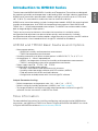
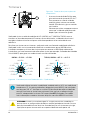
Introduction to HMD60 Series
The duct mounted HMD60 HUMICAPâ Humidity and Temperature Transmitters are designed
for monitoring humidity and temperature in demanding HVAC and light industrial applications.
HMD60 series transmitters provide stable, reliable, and highly accurate (up to ±1.5 %RH and
±0.1 °C (0.18 °F)) measurements, and are resistant to chemicals and dust.
HMD60 series transmitter options include 2 analog output models: HMD62 for measuring both
humidity and temperature, and TMD62 for temperature measurements. Both HMD62 and
TMD62 use 4 ... 20 mA loop powered current output. The HMD65 transmitter model includes
both analog and digital output options.
Thanks to easy access to electronics also when the transmitter is installed to a duct,
configuration and adjustment can be carried out quickly and conveniently. Available
configuration and adjustment interface options range from physical trimmers and DIP switches
on the transmitter's circuit board to Vaisala Insight PC software for Windowsâ.
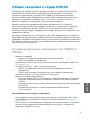
HMD62 and TMD62 Basic Features and Options
• Measurement options:
• HMD62 for humidity and temperature measurement
• TMD62 for temperature measurement
• Humidity parameters available as output options in HMD62: RH, T
d
, T
df
, A, X, T
w
, H
• Analog output: 4 ... 20 mA, loop powered
• HMD62: 2 analog output channels for humidity and temperature measurements
• TMD62: 1 analog output channel for temperature measurement
• Power supply input: 10 ... 35 VDC / 20 ... 35 VDC
• Configuration and adjustment options:
• RH and T measurement field adjustment with trimmers
• Humidity output parameter selection with DIP switches (HMD62)
• Field adjustment with MI70 hand-held indicator
• Configuration and adjustment with Vaisala Insight PC software
Output Parameter Scaling
• Default temperature analog output scale: -20 … +80 °C (-4 … +176 °F)
• Default scaling for humidity parameters (HMD62): see Table 2 (page 15).
• To change the default scaling of an analog output parameter, use Vaisala Insight PC
software. See the instructions in HMD60 User Guide.
More Information
For more detailed instructions for installing, configuring, and maintaining the HMD60 series
transmitters, see HMD62 and TMD62 User Guide in English M212016EN and HMD65 User Guide
in English M212243EN available at www.vaisala.com/HMD60.
5
ENGLISH

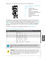
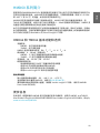
Transmitter Parts
1
2
3
4
5
6
7
8
9
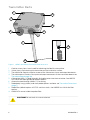
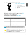
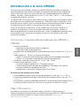
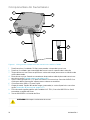
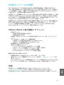
Figure 1 HMD62 and TMD62 Transmitter Parts Overview
1
Captive screw (2 pcs, cross-head) for attaching the lid of the transmitter.
2 Screw (2 pcs) for mounting the transmitter on the installation surface.
3 Transmitter lid. Open the captive screws of the lid to access input and output electronics.
4 Transmitter base. Contains the input and output connectors on the transmitter board: see
Transmitter Board (page 10).
5 Cable gland (M16 x 1.5 lead-through) for leading wires into the transmitter. See HMD60
User Guide for cable gland and conduit options.
6 Alternative lead-through (M20 x 1.5) for wiring.
7 Probe body. Long (shown) and short probe options available: see Transmitter Dimensions
(page 7).
8 Probe filter (default option: AISI 316L stainless steel). See HMD60 User Guide for filter
options.
9 HUMICAPâ sensor inside the probe filter.
Do not touch the sensor element.CAUTION!
6 M212049EN-C

Installation
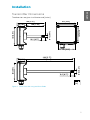
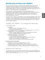
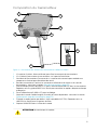
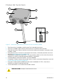
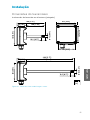
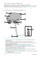
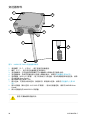
Transmitter Dimensions
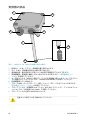
The dimensions are given in millimeters and [inches].
299 [11.77]
49 [1.92]
250 [9.84]
101 [3.97]
mm
[in]
101 [3.97]
82[3.23]
82 [3.23]
Ø 12 [0.47]
19.5 [0.77]
149 [5.87]
49 [1.92]
100 [3.94]
101 [3.97]
Ø 12 [0.47]
19.5 [0.77]
Figure 2 Dimensions with Long and Short Probe
7
ENGLISH

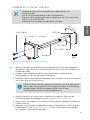
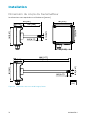
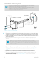
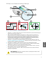
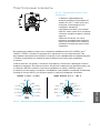
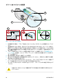
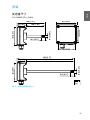
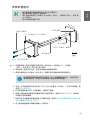
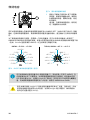
Duct Mounting Overview
90°
1
4
3
2
5
6
7
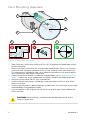
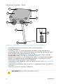
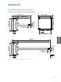
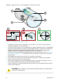
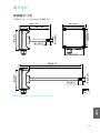
Figure 3 Duct Installation Overview
1
Make sure there is a minimum clearance of 5 m (16.5 ft) between the probe body and any
possible humidifier.
2 When installing the transmitter, drill a second hole approximately 30 cm (12 in) from the
installation hole, towards the direction of the air flow, and plug it with a removable seal.
This second hole is intended for later use in reference measurement with another device
when calibrating or adjusting the transmitter.
3 Check that the duct diameter is suitable for the probe body (see Transmitter Dimensions
(page 7)). Ideally, the sensor (probe head) should be installed in the middle of the duct.
4 Maximum air flow speed: 50 m/s (with sintered filter).
5 Avoid installing the transmitter in dead legs. Supersaturation can occur in areas where
there is no air flow.
6 Do not install the probe in a downward angle. Condensation can travel to the sensor along
the probe body if the probe points down.
7 Install the probe in a 90° angle so that the sensor is placed as close to the middle of the
duct as possible.
Avoid installing in a location where condensation can fall on the
sensor inside the duct.
CAUTION!
8 M212049EN-C

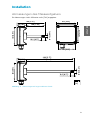
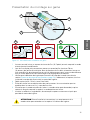
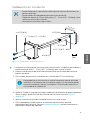
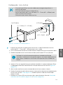
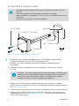
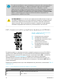
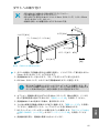
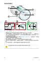
Installing into Duct
• Medium size crosshead screwdriver for mounting screws and lid screws.
• Small slotted screwdriver for screw terminals.
• Drill with 3.5 mm (0.14 in) and 13 … 15 mm (0.51 … 0.59 in) bits for making the
installation holes.
• Tools for cutting and stripping wires.
2 x Ø 3.5 [0.14]
Ø 13 ... 15 [0.51 ... 0.59]
Ø 12 [0.47]
82 [3.23]
82 [3.23]
mm
[in]
Ø 3.5 [0.14]
Ø 3.5 [0.14]
3.1 ... 3.4 Nm [2.3 ... 2.5 ft-lbs]
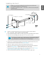
Figure 4 Drilling and Mounting Screws
1. Select an installation location for the transmitter on the duct surface and drill a
Ø 13 … 15 mm (0.51 … 0.59 in) hole for inserting the probe.
2. Push the probe through the hole on the duct until the transmitter body meets the duct.
3. Attach the transmitter body to the duct with 2 Ø 3.5 mm (0.14 in) screws.
Check that the insulation ring sits tightly over the installation hole. If the duct
has a negative pressure, external air can be drawn into the duct and aect
the measurement if the installation hole is not sealed tightly.
4. Optional: Drill a second hole for reference measurements approximately 30 cm (12 in)
from the transmitter installation hole. See Figure 3 (page 8).
5. Open the 2 captive screws on the transmitter body and remove the lid.
6. Attach the input/output wiring to the screw terminals on the transmitter component
board. See Wiring (page 11). Tighten cable glands firmly after wiring.
7. Check that the DIP switches and trimmers are in the correct position. See DIP Switch
Output Selection (HMD62) (page 15) and Trimmers (page 14).
8. Close the transmitter lid and switch on the transmitter's power supply input.
9
ENGLISH

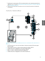
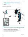
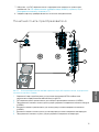
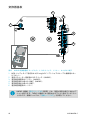
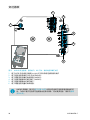
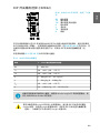
Transmitter Board
1
3
4
5
6
2
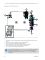
Figure 5 HMD60 Transmitter Board: Service Port, DIP switches, Trimmers and Screw Terminals
1
Service port for MI70 hand-held indicator and Insight PC software cable connection.
2 DIP switches for humidity parameter selection (HMD62).
3 Trimmer for humidity measurement adjustment (HMD62).
4 Screw terminals for humidity measurement output (HMD62).
5 Screw terminals for temperature measurement output.
6 Trimmer for temperature measurement adjustment.
The HMD62 board (shown in Figure 5 (page 10)) includes options for both
humidity and temperature output. The TMD62 board includes only components
limited to temperature output options. See Wiring (page 11) for more
information.
10 M212049EN-C

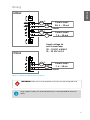
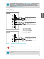
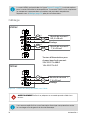
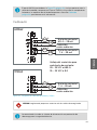
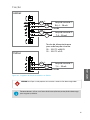
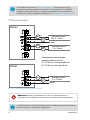
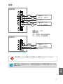
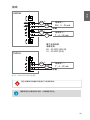
Wiring
HMD62
TMD62
mA
mA
mA
mA
+
−
+
−
mA
mA
+
−
Shield
Current loop 1:
RH, 4 ... 20 mA
Current loop 2:
T, 4 ... 20 mA
Current loop 1:
T, 4 ... 20 mA
Shield
Supply voltage for
each current loop:
20 ... 35 VDC at 600 Ω
10 ... 35 VDC at 0 Ω
Figure 6 HMD62 and TMD62 Wiring Diagrams
Make sure that you prepare or connect only de-energized wires.WARNING!
Using a power supply with overload protection is recommended for electrical
safety.
11
ENGLISH

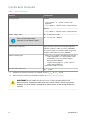
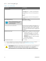
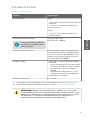
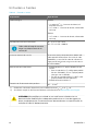
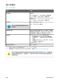
Inputs and Outputs
Table 1 Inputs and Outputs
Property Specification
Analog output HMD62:
• 1 x RH output
1)
4 ... 20 mA current, loop
powered
• 1 x T output 4 ... 20 mA current, loop powered
TMD62:
• 1 x T output 4 ... 20 mA current, loop powered
Power supply input
Each current loop output
requires its own power supply.
10 … 35 VDC (RL = 0 Ω)
20 … 35 VDC (RL = 600 Ω)
Service port connector M8 4-pin male connector for MI70 hand-held
indicator (requires cable accessory 219980SP)
or Vaisala Insight PC software cable connection
(requires USB cable accessory 219690)
2)
Cable feed throughs • M16 x 1.5 inlet, options available from Vaisala:
• Cable Gland M16 x 1.5 (Vaisala order code:
254280SP). This is the default option
delivered with HMD60.
• Conduit Fitting M16x1.5, ½”NPT (Vaisala
order code: 210675SP)
• Alternative M20 x 1.5 inlet
Screw terminal wire size
0.5 ... 1.5 mm
2
1) Available calculated parameters for HMD62 include T
d
, T
df
, A, X, T
w
, and H.
2) Vaisala Insight software for Windows available at www.vaisala.com/insight.
Do not modify the unit or use it in ways not described in the
documentation. Improper modification may lead to safety hazards, equipment
damage, failure to perform according to specification, or decreased equipment
lifetime.
CAUTION!
12 M212049EN-C

Configuration Options
Vaisala Insight Software
Vaisala Insight software is a configuration software for Vaisala Indigo-compatible probes and
transmitters. The supported operating systems are Windows 7 (64-bit), Windows 8.1 (64-bit),
and Windows 10 (64-bit).
To ensure support for your HMD60 series transmitter, download the latest version
of Insight at www.vaisala.com/insight.
With the Insight software, you can:
• See real-time measurements, device information and status.
• Configure outputs and scaling.
• Calibrate and adjust the device.
HMD60 can be connected to Insight using a Vaisala USB cable (order code 219690).
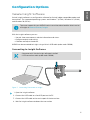
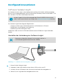
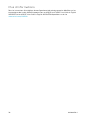
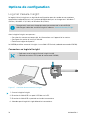
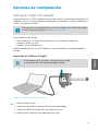
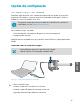
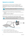
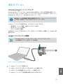
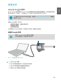
Connecting to Insight Software
• Computer with Vaisala Insight software installed
• USB connection cable (order code 219690)
Figure 7 Connecting Transmitter to Insight
1. Open the Insight software.
2. Connect the USB cable to a free USB port on the PC.
3. Connect the USB cable to the service port of the transmitter.
4. Wait for Insight software to detect the transmitter.
13
ENGLISH

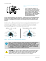
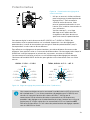
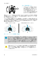
Trimmers
1
Figure 8 Component Board Adjustment
Trimmer
1 Use a Phillips head screwdriver to
rotate the RH or T adjustment trimmer.
To increase the measurement output
value, rotate the trimmer clockwise. To
decrease, rotate counterclockwise.
Note that there is a slight delay before
the measurement output changes
after rotating the trimmer.
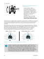
You can adjust the transmitter's RH (HMD62) or T (HMD62 and TMD62) measurement output
with the trimmers on the component board. During trimmer adjustment, the output of the
transmitter is corrected using the trimmers until the output matches the known value of a
reference.
In order to make an adjustment with the trimmers, you need a reference measurement source.
You can either insert a reference instrument into the environment that HMD60 is installed in
and compare the readings of the instruments, or remove HMD60 from the installation
environment and use a calibration and adjustment tool (for example, Vaisala Humidity
Calibrator HMK15) to generate an environment with a known value.
±0 %RH
−1 %RH
−2 %RH
−3 %RH
−4 %RH
−5 %RH
+1 %RH
+2 %RH
+3 %RH
+4 %RH
+5 %RH
±0 °C
−0.06 °C
−0.12 °C
−0.18 °C
−0.24 °C
−0.3 °C
+0.06 °C
+0.12 °C
+0.18 °C
+0.24 °C
+0.3 °C
HMD62: −5 %RH ... +5 %RH TMD62, HMD62: −0.3 °C ... +0.3 °C
RH T
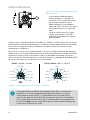
Figure 9 RH and T Trimmer Adjustment Ranges (Indicative)
You can only calibrate the relative humidity measurement (RH) and temperature
measurement (T). Other parameters (available for HMD62) are calculated
internally based on RH and T. Check that the output selection DIP switch is set to
RH when making adjustments with the physical trimmer; when using the Insight
PC software, set all DIP switches to the OFF position. For further information on
using the adjustment trimmers, see HMD60 User Guide.
If you use the Insight PC software to adjust the measurement or to
restore the factory settings, always return the physical trimmer to the middle
position before starting. When you make an adjustment with Insight, the
position in which the trimmer is at that point is set as the ±0 point.
CAUTION!
14 M212049EN-C

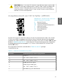
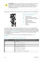
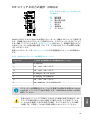
DIP Switch Output Selection (HMD62)
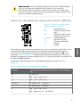
Figure 10 HMD62 DIP Switch Example: T
df
Output Selected
RH Relative humidity
Td Dew point temperature
Tdf Dew point/frost point temperature
A Absolute humidity
X Mixing ratio
Tw Wet-bulb temperature
H Enthalpy
You can change the humidity parameter that is output on the RH channel of HMD62 with the
DIP switches on the component board. Select the parameter you want the transmitter to
output by sliding the parameter's DIP switch to the right (ON). In the example in Figure 10
(page 15), the transmitter's selected output parameter is dew point/frost point temperature
(T
df
). Keep the other DIP switches in the OFF position (left).
The selected parameter uses the default scaling shown in Table 2 (page 15).
Table 2 HMD62 Default Parameter Scaling
Parameter Default Scaling for 4 … 20 mA Output Range
RH 0 … 100 %RH
T
d
-40 ... +80 °C (-40 ... +176 °F)
T
df
-40 ... +80 °C (-40 ... +176 °F)
A
0 … 300 g/m
3
(0 … 131.1 gr/ft
3
)
X 0 … 600 g/kg (0 … 4200 gr/lb)
T
w
-40 ... +80 °C (-40 ... +176 °F)
H -40 … 1600 kJ/kg (-9.5 ... 695.6 Btu/lb)
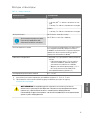
If you need to change the default scaling of a parameter, configure the output
with Vaisala Insight PC software. See the instructions in HMD60 User Guide.
If you use the Insight software to further configure the output, note
that the DIP switch selections override the Insight configuration. When using
Insight to configure the output, set all DIP switches to the OFF position (left) to
ensure they do not cause a conflict with the Insight settings.
CAUTION!
15
ENGLISH

16 M212049EN-C

Einführung zur Baureihe HMD60
Die leitungsmontierten Feuchte- und Temperaturmesswertgeber der Baureihe HMD60
HUMICAPâ sind darauf ausgelegt, Feuchte und Temperatur in anspruchsvollen HLK-
Installationen und leichten industriellen Anwendungen zu überwachen. Messwertgeber der
Baureihe HMD60 sorgen für stabile, zuverlässige und hochpräzise Messungen (bis zu ±1,5 % rF
und ±0,1 °C) und sind chemikalien- und staubbeständig.
Zu den Optionen für die Messwertgeber der Baureihe HMD60 gehören zwei
Analogausgangsmodelle: HMD62 für Feuchte- und Temperaturmessungen sowie TMD62 für
Temperaturmessungen. HMD62 und TMD62 verfügen über einen schleifengespeisten
Stromausgang mit 4 ... 20 mA. Das Messwertgebermodell HMD65 ist mit Analog- und
Digitalausgangsoptionen erhältlich.
Dank des einfachen Zugris auf die Elektronik, auch wenn der Messwertgeber in einer Leitung
installiert ist, lassen sich Konfiguration und Einstellung schnell und bequem vornehmen. Die
verfügbaren Schnittstellenoptionen für Konfiguration und Einstellung reichen von physischen
Trimmern und DIP-Schaltern auf der Platine des Messwertgebers bis hin zur PC-Software
Vaisala Insight für Windowsâ.
HMD62 und TMD62 – Grundlegende Merkmale
und Optionen
• Messoptionen:
• HMD62 für Feuchte- und Temperaturmessung
• TMD62 für Temperaturmessungen
• Als Ausgabeoptionen bei HMD62 verfügbare Feuchteparameter: rF, T
d
, T
df
, A, X, T
w
, H
• Analogausgang: 4 ... 20 mA, schleifengespeist
• HMD62: 2 analoge Ausgabekanäle für Feuchte- und Temperaturmessungen
• TMD62: 1 analoger Ausgabekanal für Temperaturmessung
• Versorgungsspannung: 10 ... 35 VDC/20–35 VDC
• Optionen für Konfiguration und Einstellung:
• rF- und T-Messfeldanpassungen mit Trimmern
• Parameterauswahl für die Feuchteausgabe mit DIP-Schaltern (HMD62)
• Feldanpassung mit tragbarem Anzeigegerät MI70
• Konfiguration und Einstellung mit der PC-Software Vaisala Insight
Ausgangsparameterskalierung
• Standardskala für Temperatur-Analogausgang: –20 … +80 °C
• Standardskalierung für Feuchteparameter (HMD62): siehe Tabelle 4 (Seite 27).
• Verwenden Sie die PC-Software Vaisala Insight, um die Standardskalierung eines
Analogausgangparameters zu ändern. Anleitungen finden Sie im HMD60 User Guide.
Weitere Informationen
Detaillierte Anleitungen zu Installation, Konfiguration und Wartung von Messwertgebern der
Baureihe HMD60 siehe HMD62 and TMD62 User Guide in English M212016EN und HMD65 User
Guide in English M212243EN unter www.vaisala.com/HMD60.
17
DEUTSCH

Messwertgeber-Teile
1
2
3
4
5
6
7
8
9
Abbildung 11 Komponenten der Messwertgeber HMD62 und TMD62 im Überblick
1
Unverlierbare Kreuzschlitzschrauben (2 Stück) zur Befestigung des
Messwertgeberdeckels.
2 Schrauben (2 Stück) zur Anbringung des Messwertgebers auf der Montagefläche.
3 Messwertgeberdeckel. Önen Sie die unverlierbaren Schrauben des Deckels, um Zugri
auf die Eingabe- und Ausgabe-Elektronik zu erhalten.
4 Messwertgebersockel. Enthält die Ein- und Ausgangsanschlüsse auf der Platine des
Messwertgebers: siehe Platine des Messwertgebers (Seite 22).
5 Kabeldurchführung (M16 x 1,5) zur Verlegung von Kabeln ins Innere des Messwertgebers.
Optionen für Kabeldurchführung und Kabelkanäle finden Sie im HMD60 User Guide.
6 Alternative Durchführung (M20 x 1,5) für Verdrahtung.
7 Sondenkörper. Lange (abgebildet) und kurze Sonden erhältlich: siehe Abmessungen des
Messwertgebers (Seite 19).
8 Sondenfilter (Standardoption: Edelstahl AISI 316L). Filteroptionen finden Sie im HMD60
User Guide.
9 HUMICAPâ-Sensor im Inneren des Sondenfilters.
Berühren Sie das Sensorelement nicht.ACHTUNG
18 M212049EN-C

Installation
Abmessungen des Messwertgebers
Die Abmessungen sind in Millimeter und in [Zoll] angegeben.
299 [11.77]
49 [1.92]
250 [9.84]
101 [3.97]
mm
[in]
101 [3.97]
82[3.23]
82 [3.23]
Ø 12 [0.47]
19.5 [0.77]
149 [5.87]
49 [1.92]
100 [3.94]
101 [3.97]
Ø 12 [0.47]
19.5 [0.77]
Abbildung 12 Abmessungen mit langer und kurzer Sonde
19
DEUTSCH

Übersicht zur Leitungsmontage
90°
1
4
3
2
5
6
7
Abbildung 13 Übersicht zur Leitungsinstallation
1
Achten Sie auf einen Freiraum von mindestens 5 m (16,5 Fuß) zwischen dem
Sondenkörper und vorhandenen Befeuchtern.
2 Bohren Sie beim Einbauen des Messwertgebers ein zweites Loch etwa 30 cm in Richtung
des Luftstroms von der Einbaubohrung entfernt und verschließen Sie es mit einem
Stopfen. Die zweite Bohrung wird später für Referenzmessungen mit einem anderen Gerät
verwendet, wenn Sie den Messwertgeber kalibrieren oder einstellen.
3 Stellen Sie sicher, dass der Leitungsdurchmesser für den Sondenkörper ausreicht (siehe
Abmessungen des Messwertgebers (Seite 19)). Im Idealfall sollte der Sensor (Sondenkopf)
in der Mitte des Rohrs angebracht werden.
4 Maximale Geschwindigkeit des Luftstroms: 50 m/s (mit Sinterfilter).
5 Vermeiden Sie den Einbau der Sonde in Totleitungen. In Bereichen, in denen kein
Luftstrom vorliegt, kann es zu Übersättigung kommen.
6 Installieren Sie die Sonde nicht in nach unten geneigter Position. Wenn die Sonde nach
unten zeigt, kann Kondenswasser am Sondenkörper entlang zum Sensor fließen.
7 Installieren Sie die Sonde in einem Winkel von 90°, damit der Sensor sich so nahe wie
möglich in der Mitte der Leitung befindet.
Vermeiden Sie die Anbringung an einem Ort, an dem sich
Kondenswasser auf dem Sensor in der Leitung absetzen kann.
ACHTUNG
20 M212049EN-C
A página está carregando...
A página está carregando...
A página está carregando...
A página está carregando...
A página está carregando...
A página está carregando...
A página está carregando...
A página está carregando...
A página está carregando...
A página está carregando...
A página está carregando...
A página está carregando...
A página está carregando...
A página está carregando...
A página está carregando...
A página está carregando...
A página está carregando...
A página está carregando...
A página está carregando...
A página está carregando...
A página está carregando...
A página está carregando...
A página está carregando...
A página está carregando...
A página está carregando...
A página está carregando...
A página está carregando...
A página está carregando...
A página está carregando...
A página está carregando...
A página está carregando...
A página está carregando...
A página está carregando...
A página está carregando...
A página está carregando...
A página está carregando...
A página está carregando...
A página está carregando...
A página está carregando...
A página está carregando...
A página está carregando...
A página está carregando...
A página está carregando...
A página está carregando...
A página está carregando...
A página está carregando...
A página está carregando...
A página está carregando...
A página está carregando...
A página está carregando...
A página está carregando...
A página está carregando...
A página está carregando...
A página está carregando...
A página está carregando...
A página está carregando...
A página está carregando...
A página está carregando...
A página está carregando...
A página está carregando...
A página está carregando...
A página está carregando...
A página está carregando...
A página está carregando...
A página está carregando...
A página está carregando...
A página está carregando...
A página está carregando...
A página está carregando...
A página está carregando...
A página está carregando...
A página está carregando...
A página está carregando...
A página está carregando...
A página está carregando...
A página está carregando...
A página está carregando...
A página está carregando...
A página está carregando...
A página está carregando...
A página está carregando...
A página está carregando...
A página está carregando...
A página está carregando...
A página está carregando...
A página está carregando...
-
 1
1
-
 2
2
-
 3
3
-
 4
4
-
 5
5
-
 6
6
-
 7
7
-
 8
8
-
 9
9
-
 10
10
-
 11
11
-
 12
12
-
 13
13
-
 14
14
-
 15
15
-
 16
16
-
 17
17
-
 18
18
-
 19
19
-
 20
20
-
 21
21
-
 22
22
-
 23
23
-
 24
24
-
 25
25
-
 26
26
-
 27
27
-
 28
28
-
 29
29
-
 30
30
-
 31
31
-
 32
32
-
 33
33
-
 34
34
-
 35
35
-
 36
36
-
 37
37
-
 38
38
-
 39
39
-
 40
40
-
 41
41
-
 42
42
-
 43
43
-
 44
44
-
 45
45
-
 46
46
-
 47
47
-
 48
48
-
 49
49
-
 50
50
-
 51
51
-
 52
52
-
 53
53
-
 54
54
-
 55
55
-
 56
56
-
 57
57
-
 58
58
-
 59
59
-
 60
60
-
 61
61
-
 62
62
-
 63
63
-
 64
64
-
 65
65
-
 66
66
-
 67
67
-
 68
68
-
 69
69
-
 70
70
-
 71
71
-
 72
72
-
 73
73
-
 74
74
-
 75
75
-
 76
76
-
 77
77
-
 78
78
-
 79
79
-
 80
80
-
 81
81
-
 82
82
-
 83
83
-
 84
84
-
 85
85
-
 86
86
-
 87
87
-
 88
88
-
 89
89
-
 90
90
-
 91
91
-
 92
92
-
 93
93
-
 94
94
-
 95
95
-
 96
96
-
 97
97
-
 98
98
-
 99
99
-
 100
100
-
 101
101
-
 102
102
-
 103
103
-
 104
104
-
 105
105
-
 106
106


em outras línguas
- español: Vaisala HMD62 Manual de usuario
- français: Vaisala HMD62 Manuel utilisateur
- 日本語: Vaisala HMD62 ユーザーマニュアル
Artigos relacionados
-
Vaisala HUMICAP HMT120 Series Manual do usuário
-
-
-
-
-
-
-
-
-