Sentiotec Lindea View Small Manual do usuário
- Tipo
- Manual do usuário

Version 10/20 Ident. no. LINDEA-V-S
EN
INSTRUCTIONS FOR INSTALLATION
English
DE
FR
IT
PT
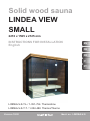
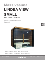
Solid wood sauna
LINDEA VIEW
SMALL
2210 x 1565 x 2125 mm
LINDEA-V-S-T-L / 1-051-756 Thermo/lime
LINDEA-V-S-T-T / 1-052-488 Thermo/Thermo

Table of Contents
1. Preparing for installation 3
1.1. Tools required 4
1.2. Maintenance and cleaning 5
1.3. Disposal 5
1.4. Parts list 6
2. Floor plan 9
2.1. Floor plan for right-hand assembly 9
2.2. Floor plan for left-hand assembly 10
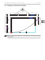
2.3. Changes for left-hand assembly 11
3. Assembling the cabin 12
3.1. Assembling the base frame 12
3.2. Assembling the cabin walls 12
3.3. Assembling the glass elements 12
3.4. Assembling the roof elements 12
3.5. Fitting the interior Lindea decor 13
3.6. Assembling the sauna benches 13
3.7. Mounting the exterior Lindea decor 13
3.8. Installing the glass door 13
3.9. Installing accessories 13
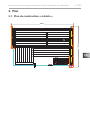
Assembly illustrations (after last language) 15

EN
Installation instructions, only for experts p. 3/32
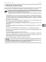
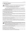
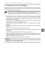
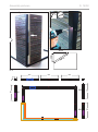
1. Preparing for installation
Read these assembly instructions carefully and keep them within reach when
using the sauna so that you can look up product information at any time.
Important note:
●Before you begin work, check the parts list to ensure that all the individual
parts have been delivered. If you discover any missing parts, notify your
dealer within 14 days of receiving the sauna cabin.
●The room that the sauna is installed in must be dry and ensure an appropriate
amount of air circulation.
● The oor must be level and even, preferably a stone or tiled oor.
●A minimum room height of 230 cm is required for the cabin installation work.
●A distance of at least 5 cm from the wall must be maintained.
●The inside of the wooden parts used must not be handled with any impreg-
nating material.
●You need an assistant for the installation.
●Wood is a natural product that can swell, shrink or warp, despite good stor-
age. For this reason, some force may be necessary during the installation.
● All screw ttings must be pre-drilled.
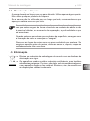
Attention!
The electrical connection may only be performed by a qualied electrician
or similarly qualied person.
These assembly instructions can also be found in the downloads section
of our website: www.sentiotec.com/downloads.

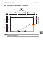
Installation instructions, only for experts p. 4/32
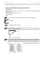
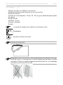
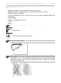
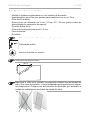
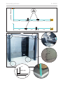
60 cm
80 cm
100 cm
This symbol indicates tips and useful information
Pre-drill
Mirror-inverted structure
Check the right angle:
Handle glass with care: Special care must be taken with the edges of
the glass – hardened glass can shatter into small pieces in the event of
impact. Insert protective cushioning (e.g: cardboard box) under the edge
of the glass.
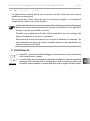
1.1. Tools required
●Hammer with a wooden head or a mallet
●Cordless screwdriver with bits for cross-head screws and Torx
●Roller tape measure
●Drill bits with a diameter of 3 mm, 10 mm, 20 - 30 mm (for sauna heater
power cable)
●Spirit level
●1.5 mm hexagonal socket wrench
●Utility knife
●Ladder

EN
Installation instructions, only for experts p. 5/32
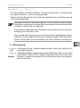
1.2. Maintenance and cleaning
●The sauna should be cleaned with a damp cloth. Only use warm water – no
cleaning products.
●We recommend heating the cabin once a month if the sauna is not used for
a long time.
Pitch pockets are not grounds for return, since they can always appear in
spruce wood and the depth at which they lie cannot be detected during
the sorting-out process.
If these are just under the surface, heat can cause them to soften and
“bleed”.
The leaking pitch can be removed with a rag soaked in acetone. If only
droplets of pitch occur, allow these to harden and then carefully scrape
them o with a knife.
1.3. Disposal
●Dispose of packaging materials in accordance with the applicable
waste disposal regulations.
●Used devices contain reusable materials as well as hazardous sub-
stances. Therefore, do not dispose of your used device with household
waste, but do so in accordance with the locally applicable regulations.

Installation instructions, only for experts p. 6/32
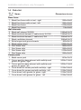
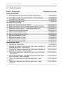
Base frame
1Black oor frame with cut-out - right 1382x40x80
1Black oor frame with cut-out - left 1382x40x80
1Black oor frame 2100x40x80
1Black oor frame 718x40x80
Wall elements
2 Black wall element W2/W5 1995x663x70
2 Black electrical element (2 cable ducts) W1/W6 1995x663x70
1 Black electrical element (1 cable duct) W4 1995x663x70
1 Black ventilation element 1995x663x70
6 Extra tongue and groove boards 663x55x15
2 Black spacer strips 2090x55x40
2 Roof frame strip 1990x40x20
1 Roof frame strip 1382x40x20
1 Roof frame strip 2100x55x20
1 Roof frame strip 1382x55x20
Corner posts
1 Black corner post 1975x70x70
1 Corner post for glass element with multiclip and
groove for glass - right 2035x110x55
1 Corner post for glass element with multiclip and
groove for glass - left 2035x110x55
1 Cover board for corner post with multiclip - right 2125x150x55
1 Cover board for corner post with multiclip - left 2125x150x55
1 Cover board with groove for glass - right 2125x150x30
1 Cover board with groove for glass - left 2125x150x30
1.4. Parts list
No. of
items Name Dimensions in mm

EN
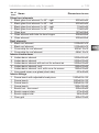
Installation instructions, only for experts p. 7/32
Glass front elements
1 Black glass front element 1x 45° - right 2035x85x55
1 Black glass front element 1x 45° - left 2035x85x55
1 Black glass front element 1x 45° - right 718x85x55
1 Black glass front element 1x 45° - left 718x85x55
1 Glass door 1975x628x8
1 Glass element with hole for door hinges 2006x680x8
2 Glass element 2006x680x8
Roof elements
1 Black roof element 2100x597x70
1 Black roof element 2100x840x70
1 Cover strip for roof element 2020x110x15
1 Cover strip for roof element 688x110x15
Interior Lindea decor
3 Lindea decor element 2020x656x40
2 Lindea decor element 2020x633x40
1 Lindea decor element with cut-out for exhaust air 2020x633x40
2 Lindea decor element, roof 1282x633x40
1 Lindea decor element, roof, with cover for sensor 1282x633x40
1 Lime wood cover over glass (short side) 633x40x40
Interior ttings
1 Sauna bench with adjustable head piece 1900x620x130
1 Sauna bench 1200x620x130
1 Sauna bench 1280x620x130
1 Sauna bench 1280x350x90
1 Bench foot - lime wood 620x445x60
4 Bench support slats 570x40x40
1 Bench support slat 965x40x40
1 Floor grid 600x270x40
No. of
items Name Dimensions in mm

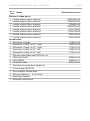
Installation instructions, only for experts p. 8/32
Exterior Lindea decor
1 Lindea exterior decor element 2090x790x40
1 Lindea exterior decor element 1950x745x40
1 Lindea exterior decor element 130x802x40
1 Lindea exterior decor element 2090x755x40
1 Lindea exterior decor element 815x130x40
1 Lindea exterior decor element 633x130x40
1 Lindea exterior decor element 745x130x40
1 Lindea exterior decor element 766x130x40
Accessories
1 Aluminium U strips 670x12x10
1 Aluminium U strip 1x 45° - right 680x12x10
1 Aluminium U strip 1x 45° - right 672x12x10
1 Aluminium U strip 1x 45° - left 680x12x10
1 Aluminium U strip 1x 45° - left 672x12x10
1 Silicone glass-glass seal WRU-60, 2m
1 LED strip, black 1890x30x35
2 LED RGBW 1890x21x17
1 Ventilation slide 520x140x15
1 Thermo-lime wood door handle set
1 2 door hinges 8653-02
1 Door magnet, sleeve plate
1 Silicone cable 4m - 5 x 2.5 mm²
1Assembly material
1 Assembly instructions
No. of
items Name Dimensions in mm

EN
Installation instructions, only for experts p. 9/32
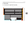
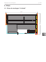
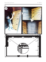
2. Floor plan
2.1. Floor plan for right-hand assembly
2210
1563

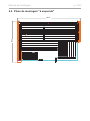
Installation instructions, only for experts p. 10/32
2.2. Floor plan for left-hand assembly
2210
1563

EN
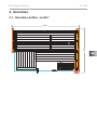
Installation instructions, only for experts p. 11/32
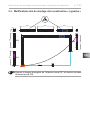
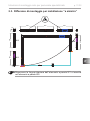
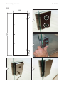
2.3. Changes for left-hand assembly
663 663 663
663
663663
70
70
W1
W2
W4
W3 W5
W6
Remove the foreign tongue from wall element W1 and insert it into wall
element W6.

Installation instructions, only for experts p. 12/32
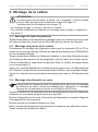
3. Assembling the cabin
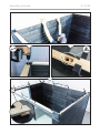
3.1. Assembling the base frame
With a hammer, carefully drive in the plastic dovetail keys on both corners of the
base frame until they are ush with the groove of the element.
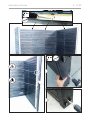
3.2. Assembling the cabin walls
Start assembly by screwing the wall elements W2 and W3 to the corner post.
Mount the spacer strips (2090x40x55) on the corner posts.
Make sure the ventilation element is correctly positioned. The other wall elements
are connected tongue and groove and are screwed together.
Now move the sauna to its nal position and check the right angles (see tip on
page 4).
Screw the “corner post with multiclip and groove for glass” to the wall element
W1. Mount the “cover board with multiclip” on the corner post.
Screw the “cover board with groove for glass” to the wall element W6.
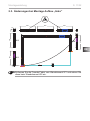
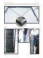
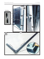
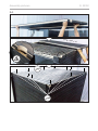
3.3. Assembling the glass elements
Place the aluminium U-prole ush on the glass elements and insert the glass
elements into the groove provided.
Mount the strip over the glass and screw it diagonally to the corner post and the
cover strip.
Then mount the third glass element.
Finally, t the roof frame strips and screw them to the wall elements. Observe
the cable outlets.
ATTENTION!
The cabin is designed for both “right-hand” and “left-hand” assembly.
Note the oor plans for this on Page 9 and Page 10.
Note illustrations from page 15 onwards.
The procedure described below is for “right-hand” assembly.
Changes for “left-hand” assembly - see Seite 11.
Note that when installing the glass element “glass with holes drilled for
door hinges”, you are dening the direction in which the door will open.
The bottom drill hole for the door hinge is 263 mm high.

EN
Installation instructions, only for experts p. 13/32
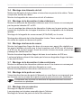
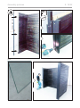
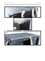
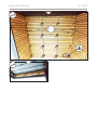
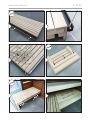
3.4. Assembling the roof elements
Insert the roof elements and screw them to the cabin walls. Observe the cable
outlets.
Fit the roof cover strips on the outside.
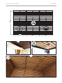
3.5. Fitting the interior Lindea decor
Mount the interior decor elements with 8 screws each, starting at the side walls
W1 and W6.
When mounting the Lindea decor elements on the rear wall, make sure the
ventilation slot is correctly positioned and the distances to the sides are correct.
Mount the cover strip (633x40x40) over the glass.
Fit the Lindea decor roof elements. Make sure the cover for the sensor above
the heater is correctly positioned.
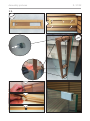
3.6. Assembling the sauna benches
Mount the support slats of the sauna bench with adjustable head piece on the side
walls so that the upper edge is 845 mm high and 50 mm from the rear wall. Before
mounting the sauna bench, drill the holes to guide cables for the LED through.
Mount the other bench support slats at a height of 355 mm.
Screw the benches to the bench support slats and the bench foot from below.
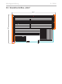
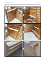
3.7. Mounting the exterior Lindea decor
Mount the exterior decor elements with 8 screws each, starting on the side walls
next to the glass elements.
Mount the exterior decor elements above the glass.
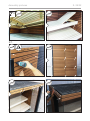
3.8. Installing the glass door
Screw the two door ttings onto the glass element, making sure that they are
straight and that the doors open outward.
3.9. Installing accessories
Mount the ventilation slide.
The door handles are screwed together from the inside.
Fit the door magnet and sleeve plate.
The alignment of the ttings is achieved by adjusting / rotating both
plastic inserts.

Installation instructions, only for experts p. 14/32

DE
MONTAGEANLEITUNG
Deutsch
Version 10/20 Artikel-Nr. LINDEA-V-S
Massivsauna
LINDEA VIEW
SMALL
2210 x 1565 x 2125 mm
LINDEA-V-S-T-L / 1-051-756 Thermo/Linde
LINDEA-V-S-T-T / 1-052-488 Thermo/Thermo

Inhaltsverzeichnis
1. Montage Vorbereitung 3
1.1. Benötigtes Werkzeug 4
1.2. Wartung und Reinigung 5
1.3. Entsorgung 5
1.4. Stückliste 6
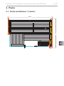
2. Grundriss 9
2.1. Grundriss Aufbau „rechts“ 9
2.2. Grundriss Aufbau „links“ 10
2.3. Änderungen bei Montage Aufbau „links“ 11
3. Montage Kabine 12
3.1. Montage Bodenrahmen 12
3.2. Montage Kabinenwände 12
3.3. Montage Glaselemente 12
3.4. Montage Dachelemente 13
3.5. Montage Lindea Dekor innen 13
3.6. Montage Saunabänke 13
3.7. Montage Lindea Dekor außen 13
3.8. Montage Glastür 13
3.9. Montage Zubehör 13
Montage Abbildungen (nach der letzten Sprache) 15

DE
Montageanleitung S. 3/32
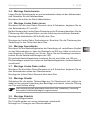
1. Montage Vorbereitung
Lesen Sie diese Montageanleitung gut durch und bewahren Sie sie in der Nähe
der Sauna auf. So können Sie jederzeit Produktinformationen nachlesen.
Wichtige Hinweise:
●Kontrollieren Sie, bevor Sie mit der Arbeit beginnen, anhand der Stückliste,
ob alle Einzelteile auch tatsächlich mitgeliefert wurden. Sollten Einzelteile
ausnahmsweise fehlen, benachrichtigen Sie spätestens 14 Tage nach Erhalt
der Kabine Ihren Händler.
●Der Raum, in dem die Saunakabine montiert wird, muss trocken sein und
eine entsprechende Luftzirkulation gewährleisten.
●Der Fußboden muss waagrecht und eben sein, bevorzugt Stein- oder Flie-
senboden.
●Für die Montagearbeiten der Kabine wird eine Mindestraumhöhe von 230 cm
benötigt.
●Es muss ein Wandabstand von mindestens 5 cm eingehalten werden.
●Die Innen zu verwendenden Holzteile dürfen nicht mit Imprägniermittel be-
handelt werden.
●Für die Montage benötigen Sie einen Helfer.
●Holz ist ein Naturprodukt, das trotz guter Lagerung aufquellen, schwinden
oder sich verziehen kann. Aus diesem Grund kann es vorkommen, dass bei
der Montage etwas Kraft aufgebracht werden muss.
●Alle Verschraubungen müssen vorgebohrt werden.
Achtung!
Der Elektroanschluss darf nur durch eine Elektrofachkraft oder eine ver-
gleichsweise qualizierte Person ausgeführt werden.
Sie nden diese Montageanleitung auch im Downloadbereich unserer
Webseite auf www.sentiotec.com/downloads.

Montageanleitung S. 4/32
Dieses Symbol kennzeichnet Tipps und nützliche Hinweise
Vorbohren
Spiegelverkehrter Aufbau
60 cm
80 cm
100 cm
Überprüfung des rechten Winkel:
Vorsichtiger Umgang mit Glas: Besondere Vorsicht gilt den Glaskanten -
Gehärtetes Glas kann bei Stößen in kleine Scherben zerspringen. Legen
Sie ein Schutzpolster (z.Bsp.: Verpackungs-Karton) unter die Glaskante.
1.1. Benötigtes Werkzeug
●Hammer und Beilageholz oder einen Gummihammer
●Akkuschrauber mit Bits für Kreuzschrauben und Torx
●Rollmaßband
●Bohrer mit Durchmesser 3 mm, 10 mm, 20 - 30 mm (für Stromkabel Saunaofen)
●Wasserwaage
●Innensechskant-Schlüssel 1,5 mm
●Universalmesser
●Leiter

DE
Montageanleitung S. 5/32
1.2. Wartung und Reinigung
●Die Sauna sollte mit einem feuchten Tuch gereinigt werden. Verwenden Sie
nur warmes Wasser - keine Reinigungsmittel.
●Wird die Sauna längere Zeit nicht benutzt, empfehlen wir, die Kabine einmal
im Monat aufzuheizen.
Harzgallen sind kein Reklamationsgrund. Da in Fichtenholz immer wieder
Harzgallen vorkommen und man beim Aussortieren nicht erkennen kann
in welcher Tiefe diese sich benden.
Wenn diese knapp unter der Oberäche sind brechen sie bei Hitzeent-
wicklung auf und „bluten“ aus.
Das ausgelaufene Harz kann man mit einem Aceton gedrängtem Lappen
entfernen. Wenn lediglich Harztropfen entstehen, lassen Sie diese aus-
härten und schaben sie anschließend mit einem Messer vorsichtig ab.
1.3. Entsorgung
●Entsorgen Sie die Verpackungsmaterialien nach den gültigen Ent-
sorgungsrichtlinien.
●Altgeräte enthalten wiederverwendbare Materialien, aber auch schäd-
liche Stoe. Geben Sie Ihr Altgerät deshalb auf keinen Fall in den
Restmüll, sondern entsorgen Sie das Gerät nach den örtlich gelten-
den Vorschriften.

Montageanleitung S. 6/32
Grundrahmen
1 Bodenrahmen mit Ausschnitt schwarz - rechts 1382x40x80
1 Bodenrahmen mit Ausschnitt schwarz - links 1382x40x80
1 Bodenrahmen schwarz 2100x40x80
1 Bodenrahmen schwarz 718x40x80
Wandelemente
2 Wandelement schwarz W2/W5 1995x663x70
2 Elektroelement schwarz (2 Kabalkanäle) W1/W6 1995x663x70
1 Elektroelement schwarz (1 Kabalkanäle) W4 1995x663x70
1 Lüftungselement schwarz 1995x663x70
6 Extra Nut-Feder Bretter 663x55x15
2 Distanzleisten schwarz 2090x55x40
2 Dachrahmenleiste 1990x40x20
1 Dachrahmenleiste 1382x40x20
1 Dachrahmenleiste 2100x55x20
1 Dachrahmenleiste 1382x55x20
Ecksteher
1 Ecksteher schwarz 1975x70x70
1 Ecksteher f. Glaselement mit Multiclip und Nut für
Glas - rechts 2035x110x55
1 Ecksteher f. Glaselement mit Multiclip und Nut für
Glas - links 2035x110x55
1 Abdeckbrett f. Ecksteher mit Multiclip - rechts 2125x150x55
1 Abdeckbrett f. Ecksteher mit Multiclip - links 2125x150x55
1 Abdeckbrett mit Nut für Glas - rechts 2125x150x30
1 Abdeckbrett mit Nut für Glas - links 2125x150x30
Az Bezeichnung Maße in mm
1.4. Stückliste
A página está carregando...
A página está carregando...
A página está carregando...
A página está carregando...
A página está carregando...
A página está carregando...
A página está carregando...
A página está carregando...
A página está carregando...
A página está carregando...
A página está carregando...
A página está carregando...
A página está carregando...
A página está carregando...
A página está carregando...
A página está carregando...
A página está carregando...
A página está carregando...
A página está carregando...
A página está carregando...
A página está carregando...
A página está carregando...
A página está carregando...
A página está carregando...
A página está carregando...
A página está carregando...
A página está carregando...
A página está carregando...
A página está carregando...
A página está carregando...
A página está carregando...
A página está carregando...
A página está carregando...
A página está carregando...
A página está carregando...
A página está carregando...
A página está carregando...
A página está carregando...
A página está carregando...
A página está carregando...
A página está carregando...
A página está carregando...
A página está carregando...
A página está carregando...
A página está carregando...
A página está carregando...
A página está carregando...
A página está carregando...
A página está carregando...
A página está carregando...
A página está carregando...
A página está carregando...
A página está carregando...
A página está carregando...
A página está carregando...
A página está carregando...
A página está carregando...
A página está carregando...
A página está carregando...
A página está carregando...
A página está carregando...
A página está carregando...
A página está carregando...
A página está carregando...
A página está carregando...
A página está carregando...
A página está carregando...
A página está carregando...
-
 1
1
-
 2
2
-
 3
3
-
 4
4
-
 5
5
-
 6
6
-
 7
7
-
 8
8
-
 9
9
-
 10
10
-
 11
11
-
 12
12
-
 13
13
-
 14
14
-
 15
15
-
 16
16
-
 17
17
-
 18
18
-
 19
19
-
 20
20
-
 21
21
-
 22
22
-
 23
23
-
 24
24
-
 25
25
-
 26
26
-
 27
27
-
 28
28
-
 29
29
-
 30
30
-
 31
31
-
 32
32
-
 33
33
-
 34
34
-
 35
35
-
 36
36
-
 37
37
-
 38
38
-
 39
39
-
 40
40
-
 41
41
-
 42
42
-
 43
43
-
 44
44
-
 45
45
-
 46
46
-
 47
47
-
 48
48
-
 49
49
-
 50
50
-
 51
51
-
 52
52
-
 53
53
-
 54
54
-
 55
55
-
 56
56
-
 57
57
-
 58
58
-
 59
59
-
 60
60
-
 61
61
-
 62
62
-
 63
63
-
 64
64
-
 65
65
-
 66
66
-
 67
67
-
 68
68
-
 69
69
-
 70
70
-
 71
71
-
 72
72
-
 73
73
-
 74
74
-
 75
75
-
 76
76
-
 77
77
-
 78
78
-
 79
79
-
 80
80
-
 81
81
-
 82
82
-
 83
83
-
 84
84
-
 85
85
-
 86
86
-
 87
87
-
 88
88


Sentiotec Lindea View Small Manual do usuário
- Tipo
- Manual do usuário
em outras línguas
Artigos relacionados
-
Sentiotec Balance View Small Manual do usuário
-
-
-
-
-
-
-
-
-
