HellermannTyton CHG900 Manual do proprietário
- Tipo
- Manual do proprietário

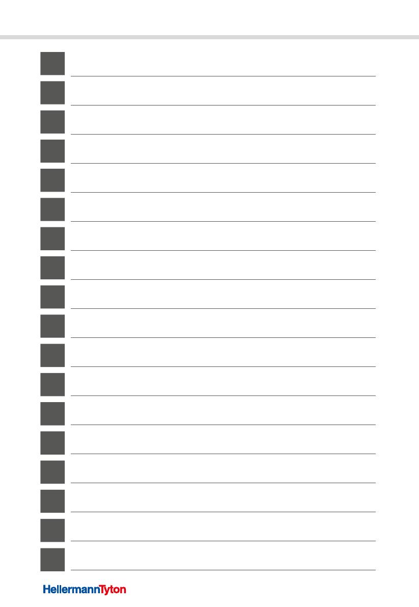
CHG900 Cordless Heat Gun
Operating Instructions
Käyttöohjeet
Bruksanvisning
Betriebsanleitung
Instrukcja obsługi Manuel d’utilisation
Návod k obsluze Manual de Instrucciones
Használati útmutatóManual de instruções
Navodila za uporabo Manuale d’uso
Bedieningshandleiding
Brugervejledning
Bruksanvisning
Instrucțiuni de utilizare
Kullanım talimatları
Руководство по эксплуатации

1
8
2
6
7
4
3
5
A
12
17 11
13
910
14
15 16
B

A
C
E
G
D
F
H
I
English
Deutsch
Français
Español
Português
Italiano
Nederlands
Dansk
Norsk
Svenska
Suomi
Polski
Cesky
Magyar
Slovenščina
Română
Türkçe
Pусский
3
9
15
21
27
33
39
45
51
57
63
69
75
81
87
93
99
105
GBDEFRESPTITNLDKNOSEFIPLCZHUSIROTRRU

Operating instructions • CHG900 • 03-2021 • 391-90010
3
GBDEFRESPTITNLDKNOSEFIPLCZHUSIROTRRU
Operating instructions
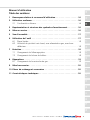
Contents
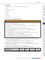
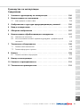
1 Information about the operating instructions ....................4
2 Intended use ............................................. 4
2.1 Conformity ................................................4
3 Representation and layout of warning instructions ............... 4
4 Initial operation .......................................... 4
5 Overview image .......................................... 5
6 Using the application tool .................................. 5
6.1 Flaring ....................................................6
6.2 Using the gas hot air blower with reflector nozzle ...................6
7 Maintenance ............................................. 6
7.1 Changing the Piezo ignition ....................................6
7.2 Changing the burner nozzle ....................................6
8 Repairs ................................................. 7
8.1 Changing the gas cartridge ....................................7
9 Decommissioning ......................................... 8
10 Spare parts and accessories ................................. 8
11 Technical data ...........................................8

Operating instructions • CHG900 • 03-2021 • 391-90010
Information about the operating instructions
4
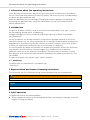
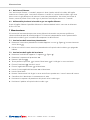
1 Information about the operating instructions
These operating instructions only apply for the gas hot air blower CHG900 and are intended for
the user. Please read these operating instructions carefully and ensure that they are understood by
any person using the application tool.
Within this document you will find images illustrating best practice guidelines for operating and
maintaining the application tools, along with contact details for your local HellermannTyton
country representative.
2 Intended use
The gas hot air blower CHG900 is used to shrink heat-shrinkable products of all types, as well as
for soft soldering, forming plastic, and defrosting.
Using gas cartridges that are not suitable or modifying the gas hot air blower is considered
non-intended use.
We are not liable for any damage and claims arising from the improper operation or use of the
cable tie installation tool, nor are we responsible for any damages caused by defects resulting from
inappropriate or unsuitable use of the tool, incorrect or careless treatment, normal wear and tear
as well as any modifications made to the tool by the customer of a third party.
The warranty/repair by HellermannTyton does not include the rectification of faults that result from
force majeure, external influences, customer neglect (e.g., modifications or attachments,
application errors etc.) or the influence of third parties. The replacement of wear parts or spare
parts during or after maintenance work carried out according to the operating instructions is also
not included.
The gas hot air blower must only be used in faultless condition.
2.1 Conformity
The device fulfills the requirements in accordance with:
• DIN EN 521
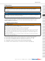
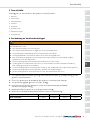
3 Representation and layout of warning instructions
The hazard level with the associated warning symbol and explanation are illustrated below:
WARNING
Possible risk of lethal or serious injuries.
NOTE
Texts with this symbol indicate situations that can lead to damage to the tool if not observed.
4 Initial operation
The application tool can be used immediately.
fTake the application tool out of the packaging and check it for damage. If damaged, inform the
supplier in writing immediately.

Operating instructions • CHG900 • 03-2021 • 391-90010
Overview image
5
GBDEFRESPTITNLDKNOSEFIPLCZHUSIROTRRU
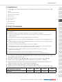
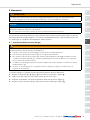
5 Overview image
An overview illustration of the gas hot air blower is provided in Figure A .
1 Burner
2 Heat protection barrier
3 Holding eye/stand
4 Gas valve
5 Gas cartridge
6 Flat nozzle
7 Reflector nozzle
8 Piezo ignition
6 Using the application tool
WARNING
Faulty operation and malfunction of the gas hot air blower result in the risk of sever injury or possible
mortal danger.
fAlways keep the nozzle a minimum distance of 2cm away from the surface.
fAlways maintain a distance of 40cm to walls and ceilings, if a flame guard is not used.
fNever leave the gas hot air blower switched on if unattended.
fAvoid a gas back-up in small rooms, gas back-up can cause gas deflagration.
fBefore storing the gas hot air blower after use, let it cool down, and then remove the gas cartridge
correctly.
fDo not use the gas hot air blower for longer than 60 minutes without interruption.
fAfter 60 min. of uninterrupted use, allow the gas hot air blower to cool down for at least 15 min.
before installing or changing the nozzle.
fDo not use a gas hot air blower that leaks, is damaged, or is not functioning properly (gas odour).
fDo not use the gas hot air blower in the vicinity of flammable materials.
fDo not expose the gas hot air blower to a temperature of, or direct sunlight above 50°C.
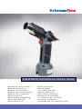
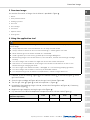
fIf desired, fit the flat nozzle 6 (Figure A ) or the reflector nozzle 7 on the barrel (Figure C ) of the
gas hot air blower.
fScrew the gas cartridge 5 (Figure A ) into the gas hot air blower (Figure D ).
fTurn the gas valve 4 (Figure A ) to the left to position + (Figure E ).
fImmediately after opening the gas valve 4 , activate the Piezo ignition 8 (Figure A ), if necessary,
several times (Figure F ).
fRegulate the gas supply by turning the gas valve (Figure G ).
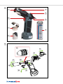
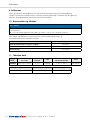
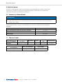
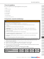
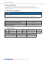
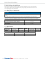
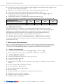
fPay attention to the distance-dependant temperature zones without nozzle (Figure H ).
Temperature zones
(distance-dependant) 2 cm 4 cm 6 cm 8 cm
Without nozzle + 900 °C + 660 °C + 480 °C + 360 °C

Operating instructions • CHG900 • 03-2021 • 391-90010
Maintenance
6
6.1 Flaring
The term flaring refers to the situation when a yellow flame instead of hot air escapes at the
nozzle. Flaring occurs when the gas hot air blower is held upside down shortly before activating
the Piezo ignition. To prevent flaring, hold the gas hot air blower in vertical position for approx.
5 seconds before use.
6.2 Using the gas hot air blower with reflector nozzle
With the reflector nozzle, soft soldering of copper pipes with a diameter of up to 32mm is
possible.
7 Maintenance
Maintenance work may only be performed by a qualified person and only with original spare parts.
This also includes opening the gas hot air blower and modifying components or functions.
7.1 Changing the Piezo ignition
fFirst pull the Piezo ignition to the front 9 (Figure B ) and then down 10 and off.
fInsert the new Piezo ignition into the gas hot air blower from below to the rear.
7.2 Changing the burner nozzle
fRemove the holding eye/stand 11 (Figure B ).
fRemove the protective casing 12 .
fPress the button 13 .
fKeep the button 13 pressed and turn the burner 14 counter clockwise by 1/4 turn.
fPull the burner 15 out to the front.
fPull the burner nozzle 16 out of the burner.
fInsert the new burner nozzle 17 into the burner.
fInsert the burner.
fTurn the burner clockwise by 1/4 turn until you hear it engage.
fCheck the the burner is properly seated.
fInsert the protective casing onto the gas hot air blower.
fPut the base on the gas hot air blower.

Operating instructions • CHG900 • 03-2021 • 391-90010
Repairs
7
GBDEFRESPTITNLDKNOSEFIPLCZHUSIROTRRU
8 Repairs
WARNING
Parts of the gas hot air blower can become extremely hot and can cause burn injuries.
fLet the gas hot air blower cool down suciently before performing tasks on the gas hot air blower.
NOTE
The gas hot air blower can be damaged through opening the housing, modifying the components or if
repairs are executed incorrectly.
fOnly have the gas hot air blower repaired by authorised personnel.
Repair work may only be performed by a qualified person and only with original spare parts.
This also includes opening the gas hot air blower and modifying components or functions.
8.1 Changing the gas cartridge
WARNING
Uncontrolled gas escape can occur due to defective seals and improperly inserted gas cartridges. This can
cause deflagrations.
fCheck the condition of the seal when replacing the gas cartridges.
fDo not use the gas hot air blower if the seal is defective.
fDo not use the gas hot air blower if it leaks, is damaged, or is not functioning properly (gas odour).
Immediately take the gas hot air blower outdoors or to a well-ventilated location, away from sparks
and flames.
fClose the gas valve and attempt to find the leak (soap/solution). If necessary let the gas completely
escape.
fReplace the gas cartridge at a well-ventilated location (if possible outdoors), away from spark sources
and other people.
The gas cartridge should always be replaced when the heating capacity decreases.
fTurn the gas valve 4 (Figure A ) to the left to position - (Figure G ).
fUnscrew the empty gas cartridge from the gas hot air blower.
fCheck the condition and correct position of the sealing ring (Figure I ).
fScrew the new gas cartridge into the gas hot air blower (Figure D ).

Operating instructions • CHG900 • 03-2021 • 391-90010
Decommissioning
8
9 Decommissioning
When used for its intended purpose, the gas hot air blower can be used without time limitation.
Should the application tool need to be withdrawn from operation, it must be disposed of correctly
in accordance with the country-specific disposal guidelines.
10 Spare parts and accessories
NOTE
The use of spare parts and accessories not approved by the manufacturer can damage the gas hot air
blower.
fUse only approved spare parts and accessories otherwise warranty claims shall be rendered void.
Spare parts and accessories can be obtained directly from the respective HellermannTyton country
representative.
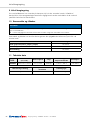
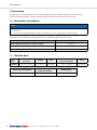
Spare parts/accessories Item no.
P445 gas cartridge (butane, propane, propylene) 391-90101
Burner nozzle 391-90012
Piezo ignition 391-90011
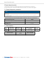
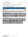
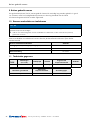
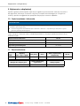
11 Technical data
TYPE Dimensions
(W x H x D)
Operating
time Weight Generated temperature
range Item no.
CHG900 290 x 310 x 110 mm approx. 1.5
hours
0.440 kg + 190 °C - 900 °C 391-90010
Maximum gas consumption Operating temperature
range Ignition type
38 g/h to -8°C Piezo ignition

Betriebsanleitung • CHG900 • 03-2021 • 391-90010
9
GBDEFRESPTITNLDKNOSEFIPLCZHUSIROTRRU
Betriebsanleitung
Inhaltsverzeichnis
1 Hinweise zur Betriebsanleitung ............................. 10
2 Bestimmungsgemäße Verwendung .......................... 10
2.1 Konformität ...............................................10
3 Darstellung und Aufbau von Warnhinweisen ................... 10
4 Inbetriebnahme .........................................10
5 Übersichtsbild ........................................... 11
6 Verwendung des Verarbeitungswerkzeuges .................... 11
6.1 Auackern ...............................................12
6.2 Verwendung des Gas-Heißluftgebläses mit Reflektordüse .............12
7 Wartung ...............................................12
7.1 Piezozündungwechsel .......................................12
7.2 Brennerdüsenwechsel .......................................12
8 Reparaturen ............................................ 13
8.1 Gaskartuschenwechsel .......................................13
9 Außerbetriebnahme ...................................... 14
10 Ersatzteile und Zubehör ................................... 14
11 Technische Daten ........................................ 14

Betriebsanleitung • CHG900 • 03-2021 • 391-90010
Hinweise zur Betriebsanleitung
10
1 Hinweise zur Betriebsanleitung
Diese Betriebsanleitung gilt ausschließlich für das Gas-Heißluftgebläse CHG900 und richtet sich an
den Benutzer. Dieser muss die Betriebsanleitung vor der Inbetriebnahme des
Verarbeitungswerkzeuges aufmerksam lesen und verstehen.
In der Betriebsanleitung befinden sich Grafiken zur Bedienung und Wartung des
Verarbeitungswerkzeuges und die Adressen der jeweiligen Ländervertretungen von
HellermannTyton.
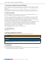
2 Bestimmungsgemäße Verwendung
Das Gas-Heißluftgebläse CHG900 dient zum Schrumpfen von wärmeschrumpfenden Produkten
aller Art sowie zum Weichlöten, Kunststoffverformen und Entfrosten.
Das Verwenden von nicht geeigneten Gaskartuschen und das Verändern des Gas-Heißluftgebläses
ist nicht bestimmungsgemäß.
Wir haften nicht für Fehler und deren Folgen, welche auf Verletzung von Bedienungs-, Wartungs-
und Austauschvorschriften, ungeeignete oder unsachgemäße Verwendung, fehlerhafte oder
nachlässige Behandlung und natürlichen Verschleiß sowie vorgenommene Eingriffe in das
Werkzeug zurückzuführen sind.
Die Gewährleistung/Instandsetzung durch HellermannTyton umfasst nicht die Beseitigung von
Fehlern, die durch höhere Gewalt, äußere Einwirkung, Verschulden des Kunden (Um- oder
Anbauten, Anwendungsfehler etc.) oder Einwirkung Dritter entstanden sind. Nicht inbegriffen ist
ferner der Ersatz von Verschleißteilen sowie der Ersatz von Ersatzteilen im Rahmen der von oder
nach Betriebsanleitung von HellermannTyton ausgeführten Wartung.
Das Gas-Heißluftgebläse darf nur in technisch einwandfreiem Zustand verwendet werden.
2.1 Konformität
Das Gerät erfüllt die Anforderungen gemäß:
• DIN EN 521
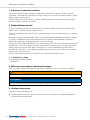
3 Darstellung und Aufbau von Warnhinweisen
Nachfolgend ist die Gefahrenstufe mit dem dazugehörigen Signalwort und Warnsymbol erläutert.
WARNUNG
Mögliche Lebensgefahr oder schwere Verletzungen.
HINWEIS
Texte mit diesem Symbol weisen auf Situationen hin, die bei Nichtbeachtung Schäden am Gerät
verursachen können.
4 Inbetriebnahme
Das Verarbeitungswerkzeug kann sofort eingesetzt werden.
fNehmen Sie das Verarbeitungswerkzeug aus der Verpackung und überprüfen Sie es auf
Beschädigungen. Teilen Sie Beschädigungen dem Lieferanten umgehend schriftlich mit.

Betriebsanleitung • CHG900 • 03-2021 • 391-90010
Übersichtsbild
11
GBDEFRESPTITNLDKNOSEFIPLCZHUSIROTRRU
5 Übersichtsbild
In Abbildung A finden Sie ein Übersichtsbild zum Gas-Heißluftgebläse.
1 Brenner
2 Hitzeschutzabdeckung
3 Halteöse / Ständer
4 Gasventil
5 Gaskartusche
6 Flachdüse
7 Reflektordüse
8 Piezozündung
6 Verwendung des Verarbeitungswerkzeuges
WARNUNG
Bei Fehlbedienung und Fehlfunktion des Gas-Heißluftgebläses besteht schwere Verletzungsgefahr oder
mögliche Lebensgefahr.
fHalten Sie mit der Düse immer einen Mindestabstand von 2 cm zur Oberfläche ein.
fHalten Sie immer einen Abstand von 40 cm zu Wänden und Decken ein, wenn kein Flammenschutz
eingesetzt wird.
fLassen Sie das eingeschaltete Gas-Heißluftgebläse nicht unbeaufsichtigt.
fVermeiden Sie einen Gasrückstau in kleinen Arbeitsräumen, um keine Gasverpuffung herbeizuführen.
fBevor Sie das Gas-Heißluftgebläse nach Benutzung verwahren, lassen Sie es abkühlen und entfernen
Sie dann die Gaskartusche ordnungsgemäß.
fBenutzen Sie das Gas-Heißluftgebläse nicht länger als 60 min. ununterbrochen.
fLassen Sie Gas-Heißluftgebläse nach 60 min. ununterbrochener Benutzung, vor der Installation oder
dem Tausch der Düsen min. 15 min. abkühlen.
fBenutzen Sie kein Gas-Heißluftgebläse, das undicht oder beschädigt ist oder schlecht funktioniert
(Gasgeruch).
fVerwenden Sie das Gas-Heißluftgebläse nicht in der Nähe von brennbaren Materialien.
fSetzen Sie das Gas-Heißluftgebläse keiner Temperatur oder Sonneneinstrahlung über 50 °C aus.
fStecken Sie, wenn gewünscht, die Flachdüse 6 (Abbildung A ) oder die Reflektordüse 7 auf den
Lauf (Abbildung C ) des Gas-Heißluftgebläses.
fSchrauben Sie die Gaskartusche 5 (Abbildung A ) in das Gas-Heißluftgebläse (Abbildung D ).
fDrehen Sie das Gasventil 4 (Abbildung A ) nach links auf Position + (Abbildung E ).
fBetätigen Sie sofort nach dem Öffnen des Gasventils 4 die Piezozündung 8 (Abbildung A ), bei
Bedarf mehrmals (Abbildung F ).
fRegulieren Sie die Gaszufuhr durch Drehen des Gasventils (Abbildung G ).
fBeachten Sie die abstandsabhängigen Temperaturzonen ohne Düse (Abbildung H ).
Temperaturzonen (abstandsabhängig) 2 cm 4 cm 6 cm 8 cm
Ohne Düse + 900 °C + 660 °C + 480 °C + 360 °C

Betriebsanleitung • CHG900 • 03-2021 • 391-90010
Wartung
12
6.1 Auackern
Als Auackern wird der Vorgang bezeichnet, wenn statt heißer Luft eine gelbe Flamme an der
Düse austritt. Das Auackern kommt zustande, wenn das Gas-Heißluftgebläse kurz vor dem
Betätigen der Piezozündung über Kopf gehalten wird. Um das Auackern zu vermeiden, halten
Sie das Gas-Heißluftgebläse vor dem Gebrauch für ca. 5 Sekunden in aufrechter Position.
6.2 Verwendung des Gas-Heißluftgebläses mit Reflektordüse
Mit der Reflektordüse ist das Weichlöten von Kupferrohren mit einem Durchmesser von bis
zu 32mm möglich.
7 Wartung
Wartungsarbeiten dürfen nur von einer qualifizierten Person und nur mit Originalersatzteilen
durchgeführt werden. Dazu gehört auch das Öffnen des Gas-Heißluftgebläses und das Verändern
von Bauteilen bzw. Funktionen.
7.1 Piezozündungwechsel
fZiehen Sie die Piezozündung erst nach vorne 9 (Abbildung B ) und anschließend nach unten 10
ab.
fSetzen Sie die neue Piezozündung von unten nach hinten in das Gas-Heißluftgebläse ein.
7.2 Brennerdüsenwechsel
fEntnehmen Sie die Halteöse / Ständer 11 (Abbildung B ).
fEntfernen Sie die Schutzverkleidung 12 .
fDrücken Sie den Knopf 13 .
fHalten Sie den Knopf 13 gedrückt und drehen Sie den Brenner 14 eine 1/4 Umdrehung gegen
den Uhrzeigersinn.
fZiehen Sie den Brenner 15 nach vorne heraus.
fZiehen Sie die Brennerdüse 16 aus dem Brenner.
fStecken Sie die neue Brennerdüse 17 in den Brenner.
fSetzen Sie den Brenner ein.
fDrehen Sie den Brenner eine 1/4 Umdrehung im Uhrzeigersinn bis Sie das Einrastgeräusch hören.
fPrüfen Sie den festen Sitz des Brenners.
fStecken Sie die Schutzverkleidung auf das Gas-Heißluftgebläse.
fStecken Sie den Fuß auf das Gas-Heißluftgebläse).

Betriebsanleitung • CHG900 • 03-2021 • 391-90010
Reparaturen
13
GBDEFRESPTITNLDKNOSEFIPLCZHUSIROTRRU
8 Reparaturen
WARNUNG
Teile des Gas-Heißluftgebläses können sehr heiß werden und können zu Verbrennungen führen.
fLassen Sie das Gas-Heißluftgebläse vor Arbeiten an dem Gas-Heißluftgebläse ausreichend abkühlen.
HINWEIS
Das Gas-Heißluftgebläse kann durch Öffnen des Gehäuses oder Verändern der Bauteile bzw. durch
unsachgemäß durchgeführte Reparaturen beschädigt werden.
fLassen Sie das Gas-Heißluftgebläse ausschließlich durch autorisiertes Personal reparieren.
Reparaturarbeiten dürfen nur von einer qualifizierten Person und nur mit Originalersatzteilen
durchgeführt werden. Dazu gehört auch das Öffnen des Gas-Heißluftgebläses und das Verändern
von Bauteilen bzw. Funktionen.
8.1 Gaskartuschenwechsel
WARNUNG
Durch defekte Dichtungen und fehlerhaft eingesetzte Gaskartuschen kann Gas unkontrolliert austreten.
Dies kann zu Verpuffungen führen.
fKontrollieren Sie beim Wechsel der Gaskartuschen den Zustand der Dichtung.
fBenutzen Sie kein Gas-Heißluftgebläse mit defekter Dichtung.
fBenutzen Sie kein Gas-Heißluftgebläse, die undicht oder beschädigt ist oder schlecht funktioniert
(Gasgeruch). Bringen Sie das Gas-Heißluftgebläse sofort ins Freie oder an einen gut belüfteten Ort,
entfernt von Funken und Flammen.
fSchließen Sie das Gasventil und versuchen Sie, das Leck zu finden (Seifenlauge). Lassen Sie das Gas ggf.
vollständig entweichen.
fWechseln Sie die Gaskartusche an einem gut belüfteten Ort (wenn möglich im Freien), entfernt von
Funkenquellen und anderen Personen.
Die Gaskartusche sollte immer dann gewechselt werden, wenn die Brennleistung nachlässt.
fDrehen Sie das Gasventil 4 (Abbildung A ) nach links auf Position - (Abbildung G ).
fSchrauben Sie die leere Gaskartusche aus dem Gas-Heißluftgebläse.
fPrüfen Sie den Zustand und die korrekte Position des Dichtrings (Abbildung I ).
fSchrauben Sie die neue Gaskartusche in das Gas-Heißluftgebläse (Abbildung D ).

Betriebsanleitung • CHG900 • 03-2021 • 391-90010
Außerbetriebnahme
14
9 Außerbetriebnahme
Das Gas-Heißluftgebläse kann bei bestimmungsgemäßer Verwendung zeitlich unbeschränkt
genutzt werden. Im Fall einer Entsorgung muss das Verarbeitungswerkzeug fachgerecht unter
Berücksichtigung der landesspezifischen Entsorgungsvorschriften entsorgt werden.
10 Ersatzteile und Zubehör
HINWEIS
Das Verwenden von nicht vom Hersteller zugelassenen Ersatzteilen und Zubehör kann das Gas-
Heißluftgebläse beschädigen.
fVerwenden Sie ausschließlich zugelassene Ersatzteile und Zubehör, ansonsten erlischt der
Gewährleistungsanspruch.
Ersatzteile und Zubehör können direkt über die jeweilige HellermannTyton-Landesvertretung
bezogen werden.
Ersatzteile/Zubehör Art.-Nr.
P445 Gaskartusche (Butan, Propan, Propen) 391-90101
Brennerdüse 391-90012
Piezozündung 391-90011
11 Technische Daten
TYP Abmessungen
(L x H x B) Betriebsdauer Gewicht Erzeugter
Temperaturbereich Art.-Nr.
CHG900 290 x 310 x 110 mm ca. 1,5 Std. 0,440 kg + 190 °C - 900 °C 391-90010
Maximaler Gasverbrauch Einsatz Temperaturbereich Zündungsart
38 g/h bis -8 °C Piezozündung

Manuel d‘utilisation • CHG900 • 03-2021 • 391-90010
15
GBDEFRESPTITNLDKNOSEFIPLCZHUSIROTRRU
Manuel d'utilisation
Table des matières
1 Remarques relatives à ce manuel d'utilisation .................. 16
2 Utilisation conforme ...................................... 16
2.1 Conformité ou Norme .......................................16
3 Représentation et structure des symboles d'avertissement ........ 16
4 Mise en service .......................................... 16
5 Vue d’ensemble ......................................... 17
6 Utilisation de l'outil ...................................... 17
6.1 Phase liquide ..............................................18
6.2 Utilisation du pistolet à air chaud, avec alimentation gaz, avec buse
déflecteur ................................................18
7 Entretien ...............................................18
7.1 Changement de l'allumage piézo ...............................18
7.2 Changement de la buse du brûleur .............................18
8 Réparations ............................................ 19
8.1 Changement de la cartouche de gaz ............................19
9 Mise hors service ........................................ 20
10 Pièces de rechange et accessoires ...........................20
11 Caractéristiques techniques ................................ 20

Manuel d‘utilisation • CHG900 • 03-2021 • 391-90010
Remarques relatives à ce manuel d'utilisation
16
1 Remarques relatives à ce manuel d'utilisation
Ce manuel s'applique uniquement au pistolet à air chaud CHG900, avec alimentation gaz, et
s'adresse à l'utilisateur. Celui-ci doit lire, étudier et veiller à bien comprendre toutes les mises en
garde et instructions avant la mise en service de l’outil.
Ce manuel contient des illustrations pour l'utilisation et l'entretien de l'outil ainsi que les contacts
des représentants nationaux de HellermannTyton.
2 Utilisation conforme
Le pistolet à air chaud CHG900, avec alimentation gaz, convient au rétreint de tous types de
produits thermorétractables ainsi que pour le brasage, le thermoformage du plastique et le
dégivrage.
L'utilisation de cartouches de gaz non adaptées et la transformation du pistolet à air chaud, avec
alimentation gaz, ne sont pas conformes.
HellermannTyton n’assume aucune responsabilité pour des erreurs et leurs conséquences
consécutives au non-respect des prescriptions d’utilisation, d'entretien et de remplacement, ou à
une utilisation inappropriée ou incorrecte, à un traitement erroné ou des négligences, à l’usure
naturelle ainsi qu’aux altérations apportées à l’outil.
La garantie/remise en état par HellermannTyton ne comprend pas l'élimination de défauts résultant
de cas de force majeure, d'influences extérieures, de la faute du client (transformations ou
modifications, erreurs d'utilisation, etc.) ou d'actions de tiers. Ne sont également pas inclus le
remplacement des pièces d'usure ainsi que le remplacement des pièces de rechange dans le cadre
de l'entretien effectué par HellermannTyton selon le manuel d'utilisation.
Le pistolet à air chaud, avec alimentation gaz, doit exclusivement être utilisé s’il est en bon état de
fonctionnement.
2.1 Conformité ou Norme
L’appareil satisfait aux exigences conformément à la:
• DIN EN 521
3 Représentation et structure des symboles d'avertissement
Les niveaux de danger sont expliqués ci-dessous avec le libellé et le symbole d'avertissement.
AVERTISSEMENT
Ce symbole vous avertit au sujet des risques potentiels qui peuvent résulter en blessures sévères ou mortelles.
REMARQUE
Les textes comportant ce symbole signalent des situations pouvant provoquer des dommages sur l’appareil
en cas de non-respect.
4 Mise en service
L'outil peut être utilisé immédiatement.
fDéballez l'outil de pose et vérifiez qu'il ne présente aucun dommage. Faites immédiatement part
des dommages au fournisseur par écrit.

Manuel d‘utilisation • CHG900 • 03-2021 • 391-90010
Vue d’ensemble
17
GBDEFRESPTITNLDKNOSEFIPLCZHUSIROTRRU
5 Vue d’ensemble
La représentation A est une vue d’ensemble du pistolet à air chaud, avec alimentation gaz.
1 Brûleur
2 Revêtement de protection contre la chaleur
3 Anneau d'accrochage / support
4 Arrivée de gaz
5 Cartouche de gaz
6 Buse large
7 Buse déflecteur
8 Bouton d’allumage piézo
6 Utilisation de l'outil
AVERTISSEMENT
Toute mauvaise utilisation ou mauvais fonctionnement du pistolet à air chaud, avec alimentation gaz, peut
entraîner de graves blessures, voire potentiellement mortelles.
fConservez toujours une distance minimale de 2cm entre la buse et la surface de travail.
fConservez toujours une distance de 40cm par rapport aux murs et aux plafonds, lorsqu’il n’y a pas de
protection contre la flamme.
fNe laissez jamais le pistolet à air chaud, avec alimentation gaz, allumé et sans surveillance.
fEvitez les refoulements de gaz dans des locaux exigus, pour éviter toute déflagration de gaz.
fAvant de ranger l’outil après son utilisation, vérifiez que la buse du pistolet à air chaud est parvenue à
température ambiante et retirez alors la cartouche de gaz selon les instructions.
fN’utilisez pas le pistolet à air chaud, avec alimentation gaz, de manière ininterrompue et pendant plus
de 60minutes.
fLaissez refroidir le pistolet à air chaud, à alimentation gaz, au moins 15min. après une utilisation
ininterrompue de 60min. et avant l'installation ou le remplacement de la buse.
fN’utilisez pas un appareil qui fuit, qui est détérioré ou qui fonctionne mal (odeur de gaz).
fN’utilisez pas l’appareil à proximité de matériaux inflammables.
fN'exposez pas le pistolet à air chaud avec alimentation à gaz à une température ou un rayonnement
solaire supérieur à 50° C.
fSi nécessaire, branchez la buse large 6 (représentation A ) ou la buse déflecteur 7 sur le canon
(représentation C ) du pistolet à air chaud.
fVissez la cartouche de gaz 5 (représentation A ) dans le pistolet à air chaud (représentation D ).
fTournez l'arrivée de gaz 4 (représentation A ) vers la gauche en position + (représentation E ).
fImmédiatement après l’ouverture de l’arrivée de gaz 4 , actionnez le bouton d’allumage piézo 8
(représentation A ). Répétez l'opération plusieurs fois si nécessaire (représentation F ).
fRéglez l’alimentation en gaz en tournant la vanne d’arrivée de gaz (représentation G ).
fTenez compte des zones de température en fonction de la distance, sans buse (représentation H ).
Zones de température
(en fonction de la distance) 2cm 4cm 6cm 8cm
Sans buse + 900 °C + 660 °C + 480 °C + 360 °C

Manuel d‘utilisation • CHG900 • 03-2021 • 391-90010
Entretien
18
6.1 Phase liquide
L’apparition brève d’une flamme jaune par la buse de l’outil au lieu d’air chaud est appelée « phase
liquide ». Ce phénomène peut se produire lorsque le pistolet à air chaud a été maintenu tête en
bas avant l’activation du bouton d’allumage piézo. Afin d’éviter la phase liquide, tenez le pistolet à
air chaud tête en haut et attendre 5 secondes avant de le mettre en route.
6.2 Utilisation du pistolet à air chaud, avec alimentation gaz, avec buse déflecteur
La buse déflecteur permet de souder des tubes en cuivre d’un diamètre maximal de 32mm.
7 Entretien
Les opérations d'entretien doivent uniquement être effectuées par une personne qualifiée et
seulement avec des pièces de rechange d'origine. Cela inclut l’ouverture du boîtier du pistolet à air
chaud, avec alimentation gaz, ainsi que l’altération de ses constituants ou de ses fonctions.
7.1 Changement de l'allumage piézo
fTirez l'allumage piézo vers l'avant 9 (représentation B ), puis retirez-le par le bas 10 .
fIntroduisez le nouvel allumage piézo du bas vers l'arrière dans le pistolet à air chaud.
7.2 Changement de la buse du brûleur
fRetirez l'anneau d'accrochage / le support 11 (représentation B ).
fRetirez le revêtement de protection 12 .
fAppuyez sur le bouton 13 .
fMaintenez le bouton 13 enfoncé et tournez le brûleur 14 d'un quart de tour dans le sens
antihoraire.
fExtrayez le brûleur 15 par l'avant.
fRetirez la buse 16 du brûleur.
fIntroduisez une buse neuve 17 dans le brûleur.
fIntroduisez le brûleur.
fTournez le brûleur d'un quart de tour dans le sens horaire jusqu'à ce que vous entendiez un clic de
verrouillage.
fVérifiez que le brûleur est fixé solidement.
fEnfoncez le revêtement de protection sur le pistolet à air chaud.
fEnfoncez le pied sur le pistolet à air chaud.
A página está carregando...
A página está carregando...
A página está carregando...
A página está carregando...
A página está carregando...
A página está carregando...
A página está carregando...
A página está carregando...
A página está carregando...
A página está carregando...
A página está carregando...
A página está carregando...
A página está carregando...
A página está carregando...
A página está carregando...
A página está carregando...
A página está carregando...
A página está carregando...
A página está carregando...
A página está carregando...
A página está carregando...
A página está carregando...
A página está carregando...
A página está carregando...
A página está carregando...
A página está carregando...
A página está carregando...
A página está carregando...
A página está carregando...
A página está carregando...
A página está carregando...
A página está carregando...
A página está carregando...
A página está carregando...
A página está carregando...
A página está carregando...
A página está carregando...
A página está carregando...
A página está carregando...
A página está carregando...
A página está carregando...
A página está carregando...
A página está carregando...
A página está carregando...
A página está carregando...
A página está carregando...
A página está carregando...
A página está carregando...
A página está carregando...
A página está carregando...
A página está carregando...
A página está carregando...
A página está carregando...
A página está carregando...
A página está carregando...
A página está carregando...
A página está carregando...
A página está carregando...
A página está carregando...
A página está carregando...
A página está carregando...
A página está carregando...
A página está carregando...
A página está carregando...
A página está carregando...
A página está carregando...
A página está carregando...
A página está carregando...
A página está carregando...
A página está carregando...
A página está carregando...
A página está carregando...
A página está carregando...
A página está carregando...
A página está carregando...
A página está carregando...
A página está carregando...
A página está carregando...
A página está carregando...
A página está carregando...
A página está carregando...
A página está carregando...
A página está carregando...
A página está carregando...
A página está carregando...
A página está carregando...
A página está carregando...
A página está carregando...
A página está carregando...
A página está carregando...
A página está carregando...
A página está carregando...
A página está carregando...
A página está carregando...
A página está carregando...
A página está carregando...
-
 1
1
-
 2
2
-
 3
3
-
 4
4
-
 5
5
-
 6
6
-
 7
7
-
 8
8
-
 9
9
-
 10
10
-
 11
11
-
 12
12
-
 13
13
-
 14
14
-
 15
15
-
 16
16
-
 17
17
-
 18
18
-
 19
19
-
 20
20
-
 21
21
-
 22
22
-
 23
23
-
 24
24
-
 25
25
-
 26
26
-
 27
27
-
 28
28
-
 29
29
-
 30
30
-
 31
31
-
 32
32
-
 33
33
-
 34
34
-
 35
35
-
 36
36
-
 37
37
-
 38
38
-
 39
39
-
 40
40
-
 41
41
-
 42
42
-
 43
43
-
 44
44
-
 45
45
-
 46
46
-
 47
47
-
 48
48
-
 49
49
-
 50
50
-
 51
51
-
 52
52
-
 53
53
-
 54
54
-
 55
55
-
 56
56
-
 57
57
-
 58
58
-
 59
59
-
 60
60
-
 61
61
-
 62
62
-
 63
63
-
 64
64
-
 65
65
-
 66
66
-
 67
67
-
 68
68
-
 69
69
-
 70
70
-
 71
71
-
 72
72
-
 73
73
-
 74
74
-
 75
75
-
 76
76
-
 77
77
-
 78
78
-
 79
79
-
 80
80
-
 81
81
-
 82
82
-
 83
83
-
 84
84
-
 85
85
-
 86
86
-
 87
87
-
 88
88
-
 89
89
-
 90
90
-
 91
91
-
 92
92
-
 93
93
-
 94
94
-
 95
95
-
 96
96
-
 97
97
-
 98
98
-
 99
99
-
 100
100
-
 101
101
-
 102
102
-
 103
103
-
 104
104
-
 105
105
-
 106
106
-
 107
107
-
 108
108
-
 109
109
-
 110
110
-
 111
111
-
 112
112
-
 113
113
-
 114
114
-
 115
115
-
 116
116


HellermannTyton CHG900 Manual do proprietário
- Tipo
- Manual do proprietário
em outras línguas
Artigos relacionados
Outros documentos
-
Metabo H 1600 Heissluftpistole Manual do proprietário
-
Beta 1850C Instruções de operação
-
Metabo HE 23-650 Control Instruções de operação
-
-
Parkside PHLG 2000-2 Operation and Safety Notes
-
Ferm HAM1010 Manual do usuário
-
-
-
 JBM 53145 Guia de usuario
-
Bosch PHG 630 DCEPKP 30 LE Manual do proprietário
