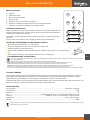
Ibiza Light PAR-MINI-STR Manual do proprietário
- Categoria
- Estroboscópios
- Tipo
- Manual do proprietário

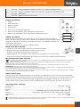
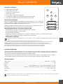
4-IN-1 RGBW LED PAR CAN
WITH SMD LED STROBE
MANUAL
Ref.
PAR-MINI-STR
FR - Manuel d'Utilisation - p. 6
DE - Bedienungsanleitung - S. 10
NL - Handleiding - p. 14
ES - Manual de Uso - p. 18
RO - Manual de Instrucţiuni - p. 22
SI - Navodila za uporabo - s. 26
HR - Upute za uporabu - s. 30
IT - Manuale di istruzioni - p. 34
PT - Manual de Instruções - p. 38

Manual - PAR-MINI-STR
2
©Copyright LOTRONIC 2021
4-IN-1 RGBW LED PAR CAN WITH SMD LED STROBE
INSTRUCTION MANUAL
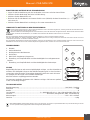
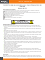
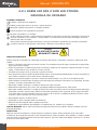
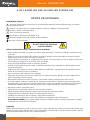
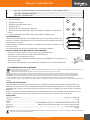
EXPLANATION OF SYMBOLS ON THE SILKSCREEN
The triangle containing a lightning symbol is used to indicate whenever your health is at risk (due to electro-
cution, for example).
An exclamation mark in a triangle indicates particular risks in handling or operating the appliance.
The unit complies with CE standards
For indoor use only
Protection class II. Requires no earth connection
0.5m
Minimum distance between the appliance and other objects
Don’t stare into the light beam
CAUTION
DO NOT OPEN THE HOUSING
SHOCK HAZARD
IMPORTANT SAFETY INSTRUCTIONS AND DANGER WARNINGS
• Please read these instructions carefully, they include important information about the installation, usage and
maintenance of this product.
• Please keep this User Guide for future reference. If you sell the unit to another user, be sure that he also
receives this instruction booklet.
• Always make sure that you are connecting to the proper voltage, and that the line voltage you are connecting
to is not higher than that stated on the decal or rear panel of the xture.
• This product is intended for indoor use only!
• To prevent risk of re or shock, do not expose xture to rain or moisture. Make sure there are no ammable
materials close to the unit while operating.
• The unit must be installed in a location with adequate ventilation, at least 20in (50cm) from adjacent surfaces.
Be sure that no ventilation slots are blocked.
• Always disconnect from power source before servicing.
• Secure xture to fastening device using a safety chain. Never carry the xture solely by its head. Use its carry-
ing handles.
• Maximum ambient temperature (Ta) is 104° F (40°C). Do not operate the xture at temperatures higher than
this.
• In the event of a serious operating problem, stop using the unit immediately. Never try to repair the unit by
yourself. Repairs carried out by unskilled people can lead to damage or malfunction. Please contact the near-
est authorized technical assistance center. Always use the same type of spare parts.
• Don’t connect the device to a dimmer pack.
• Make sure the power cord is never crimped or damaged.
• Never disconnect the power cord by pulling or tugging on the cord.
• Avoid direct eye exposure to the light source while it is on.
• The lamps are not replaceable. If they are damaged, the whole unit must be discarded
• The product is for decorative purposes only and not suitable as a household room illumination.
• DISCONNECT DEVICE: Where the MAINS plug or an appliance coupler is used as the disconnect device, the
disconnect device shall remain readily operable.
INSTALLATION
The unit should be mounted via its screw holes on the bracket. Always ensure that the unit is rmly xed to
avoid vibration and slipping while operating. Always ensure that the structure to which you are attaching the unit
is secure and is able to support a weight of 10 times of the unit’s weight.

Manual - PAR-MINI-STR
3
www.ibiza-light.com
EN
FIXTURE LINKING
You will need a serial data link to run light shows of one or more xtures using a DMX-512 controller or to run
synchronized shows on two or more xtures set to a master/slave operating mode. The combined number of
channels required by all xtures on a serial data link determines the number of xtures that the data link can
support.
Important: Fixtures on a serial/data link must be daisy chained in one single line.
CABLE CONNECTORS
Cabling must have a male XLR connector on one end and a female XLR connector on the other end.
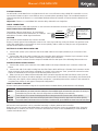
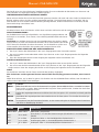
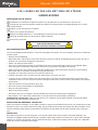
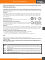
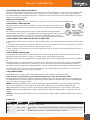
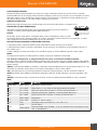
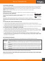
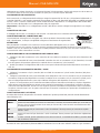
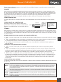
DMX CONNECTOR CONFIGURATION
INPUT
COMMON
DMX +
DMX-
Resistance 120 ohm
1/ 4w between pin 2
(DMX-) and pin 3
(DMX+) of the last
fixture.
Termination reduces signal errors. To avoid signal
transmission problems and interference, it is always
advisable to connect a DMX signal terminator.
CAUTION
Do not allow contact between the common and the
xture’s chassis ground. Grounding the common can cause a ground loop, and your xture may perform errat
-
ically. Test cables with an ohm meter to check correct polarity and to make sure the pins are not grounded or
shorted to the shield or each other.
SETTING UP A DMX SERIAL DATA LINK
1. Connect the (male) 3 pin connector side of the DMX cable to the output (female) 3 pin connector of the
controller.
2. Connect the end of the cable coming from the controller which will have a (female) 3 pin connector to the
input connector of the next fixture consisting of a (male) 3 pin connector.
3. Then, proceed to connect from the output as stated above to the input of the following fixture and so on.
MASTER/SLAVE FIXTURE LINKING
1. Connect the (male) 3 pin connector of the DMX cable to the output (female) 3 pin connector of the first
fixture.
2. Connect the end of the cable coming from the first fixture which will have a (female) 3 pin connector to the
input connector of the next fixture consisting of a (male) 3 pin connector. Then, proceed to connect from the
output as stated above to the input of the following fixture and so on
3. Often, the set up for Master-Slave and Stand-alone operation requires that the first fixture in the chain be
initialized for this purpose via either settings in the control panel or DIP-switches. Secondarily, the fixtures that
follow may also require a slave setting. Please consult the '' Operating Instructions» section in this manual for
complete instructions for this type of setup and configuration.
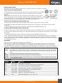
HOW TO CONTROL THE UNIT
Access control panel functions using the four panel buttons located directly underneath the LCD Display.
Button Function
MENU press MENU key to enter into the submenus. Press MENU again to leave the sub-menu. If no key is
pressed during 30 seconds, the unit will go back to MENU display automatically
UP press UP key to increase the displayed values. Keep pressed to increase the values quickly
DOWN press DOWN key to decrease the displayed values. Keep pressed to decrease the values quickly
ENTER in normal status, this button has no function. In edit mode, press ENTER to enter into the sub-menu
All functions and operations can be controlled manually on display without DMX controller.
Enter into menu by pressing the MENU button and select the menu item via the up and down keys. Press the
ENTER button to conrm your choice. Increase or decrease the value via the UP/DOWN keys. Press ENTER to
conrm and exit the menu.

Manual - PAR-MINI-STR
4
©Copyright LOTRONIC 2021
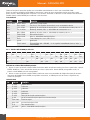
LCD DISPLAY
MODE MENU FUNCTION
A001~A511 A001~A511 DMX Mode / Jump Strobe
Au**
FF**
Au 1~Au15 Fixed Color, 1~15 means 4 color mixing ( see details below
FF 1~FF99 Jump Change, Value +, Color change speed +
CC** CC 1~CC99 Gradual Change, Value +, Color change speed +
EE** EE 1~EE99 Pulse Change, Value +, Color change speed +
F*** F001~F009 No Strobe
F010~F255 Value +, Strobe speed +
AuTo AuTo Auto Mode, Replay FF**, CC**, EE**, F***
Soud Soud Sound Mode 1
VOL1~VOL9 Press ENTER "VOL"STROBE, “1~9" means Sound Sensitivity, Value +, Sensi
-
tivity +
AU ** COLOR CHANGE TABLE
Color 1 2 3 4 5 6 7 8 9 10 11 12 13 14 15
R ON ON ON ON ON ON ON ON
G ON ON ON ON ON ON ON ON
B ON ON ON ON ON ON ON ON
W ON ON ON ON ON ON ON ON
Marked with "ON" means the color is ON, blank spaces mean "OFF".
SET DMX ADDRESS CODE:
1. Enter into the menu by pressing the MENU button. Select d001 via the up and down keys and press ENTER.
Modify the value via the up and down keys. Press ENTER to save and exit, or press the MENU button to exit
without saving.
2. Enter into menu by pressing the MENU button, select among a variety of operating codes via the UP/DOWN
keys. Press ENTER to save and run or MENU to leave the menu and return to the operating modes.
DMX CHANNELS
CH VALUE FUNCTION
1 0~255 Master dimmer
2 0~255 R dimmer
3 0~255 G dimmer
4 0~255 B dimmer
5 0~255 W dimmer
6
0~255 Strobe function selection
0~99 Par & Strobe Light ash at the same time
100~199 Par Light ash
200~255 Strobe Light ash
7
0~9 No Strobe
10~255 Value +, Strobe speed -
8
0~50 Manual Mode, Available from CH1-CH7
51~100 Jump change, Same as 'FF**' mode, CH6 adjust speed
101~150 Gradual change, Same as 'CC**' mode, CH6 adjust speed
151~200 Pulse change, Same as 'EE**' mode, CH6 adjust speed
201~250 Auto Mode
251~255 Sound Mode

Manual - PAR-MINI-STR
5
www.ibiza-light.com
EN
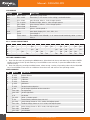
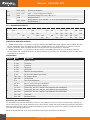
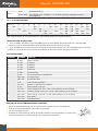
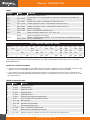
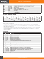
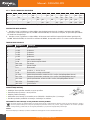
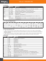
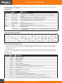
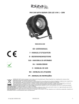
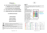
REMOTE CONTROL
1
2
3 3 3
4
5
6
7
PRO LIGHT
SPEED/SEN
SPEED/STROBE
1. ON/OFF
2. Automatic mode
3. Music controlled modes
4. Strobe mode
5. Selection of one of the built-in programs
6. Setting of sensitivity and speed of the music controlled mode
7. Setting of sensitivity and speed of the strobe mode
IR REMOTE CONTROLLER
Please operate the remote control within a distance of 6m and 30° between the
remote and the appliance. Aim the remote at the sensor. Remove all obstacles
between the remote and the sensor.
The remote control might not work properly if the sensor is exposed to strong
sunshine.
If the remote control doesn’t work properly, please check the batteries.
INSTALLING THE BATTERIES IN THE REMOTE CONTROL
• Place the remote face down on a at surface.
• Push the compartment cover into the direction of the arrow.
• Slide the battery compartment open.
• Remove the old battery and install the new one (CR2032) with the plus (+) symbol facing
up.
• Gently slide the battery compartment closed. It locks automatically.
RECOMMENDATIONS FOR BATTERIES
This symbol indicates that used batteries should not be disposed of with household waste but deposed correctly in accordance with
your local regulations..
Batteries shall not be exposed to excessive heat such as sunshine, re or the like.
When the internal batteries are not to be used, remove them to avoid damage caused by battery leakage or corrosion.
ATTENTION: Danger of explosion if battery is incorrectly placed. Only replace by the same or equivalent type.
WARNING :Do not swallow the battery. Danger of chemical burns. Keep new and old batteries out of the reach of children.
If the battery compartment doesn’t close properly, stop using the product and keep it out of the reach of children.
If you are in doubt whether the batteries have been swallowed or introduced into any other part of the body, contact immediately a doctor.
FIXTURE CLEANING
The cleaning of internal and external optical lenses and/or mirrors must be carried out periodically to optimize
light output. Cleaning frequency depends on the environment in which the xture operates: damp, smoky or
particularly dirty surrounding can cause greater accumulation of dirt on the unit’s optics.
Clean with soft cloth using normal glass cleaning uid. Always dry the parts carefully. Clean the external optics at
least every 20 days. Clean the internal optics at least every 30/60 days.
SPECIFICATIONS:
Input voltage: .................................................................................................................. 100-240V~ 50/60Hz
Consumption .............................................................................................................................................15W
Channels ........................................................................................................................................................8
LED: ......................................................................3 x 4W RGBW LED 4-in-1; 18x 0.5W white SMD 5730 LED
Function: ............................................................................. DMX512, Auto-run, Sound active, remote control
Dimensions .....................................................................................................................125 x 125 x 125mm
Weight: ....................................................................................................................................................600g
Electric products must not be put into household waste. Please bring them to a recycling centre. Ask your local authorities or your
dealer about the way to proceed.

Manual - PAR-MINI-STR
6
©Copyright LOTRONIC 2021
PROJECTEUR PAR A LED RGBW 4-EN-1 AVEC STROBOSCOPE A
LED SMD
MANUEL D'UTILISATION
EXPLICATION DES SYMBOLES
L’éclair dans le triangle attire l’attention sur un danger physique (due à une électrocution p.ex.).
Le point d’exclamation dans le triangle indique un risque dans la manipulation ou l’utilisation de l’appareil.
En conformité avec les exigences de la norme CE
Utilisation uniquement à l’intérieur
Classe de protection II: Sans mise à la terre
0.5m
Distance minimum entre l’appareil et d’autres objets
Ne pas regarder directement dans le rayon lumineux
CONSIGNES DE SECURITE
• Lisez attentivement ce manuel qui contient des informations importantes sur l’installation, l’utilisation et l’en-
tretien de cet appareil. Conservez le manuel pour référence ultérieure.
• Assurez-vous que la tension secteur convient à cet appareil et qu’elle ne dépasse pas la tension d’alimenta-
tion indiqué sur la plaque signalétique de l’appareil.
• Uniquement pour utilisation à l’intérieur!
• A n d’éviter tout risque d’incendie ou de choc électrique, ne pas exposer cet appareil à la pluie ou à l’humidi-
té. Assurez-vous qu’aucun objet in ammable ne se trouve à proximité de l’appareil pendant son fonctionne-
ment.
• Installez l’appareil à un endroit bien ventilé à une distance minimum de 50cm de toute surface. Assurez-vous
que les fentes de ventilation ne sont pas bloquées.
• Débranchez l’appareil du secteur avant toute manipulation ou entretien.
• Sécurisez l’appareil sur le dispositif de xation au moyen d’une chaîne. Ne portez jamais l’appareil en le te-
nant par le boîtier. Tenez-le par l’étrier.
• La température ambiante ne doit pas dépasser 40°C. Ne pas faire fonctionner l’appareil à des températures
supérieures.
• En cas de dysfonctionnement, arrêtez immédiatement l’appareil. N’essayez jamais de réparer l’appareil par
vous-même. Une réparation mal faite peut entraîner des dommages et des dysfonctionnements. Contactez un
service technique agréé. Utilisez uniquement des pièces détachées identiques aux pièces d’origine.
• Ne pas brancher l’appareil sur un variateur.
• Ne pas exposer vos yeux à la source lumineuse.
• Assurez-vous que le cordon d’alimentation n’est jamais écrasé ni endommagé.
• Ne jamais débrancher l’appareil en tirant sur le cordon.
• Les lampes ne sont pas remplaçables. Si elles sont défectueuses, l'appareil doit être mis au rebut.
• Le luminaire ne doit servir qu’à des ns décoratives et ne convient pas comme éclairage domestique normal.
• Dispositif de déconnexion: Lorsque le cordon d'alimentation ou un coupleur d'appareil est utilisé comme
dispositif de déconnexion, ce dispositif doit rester facilement accessible; si un interrupteur omnipolaire est
utilisé comme dispositif de déconnexion, l'emplacement sur l'appareil et la fonction de l'interrupteur doit être
décrite, et le commutateur doit rester facilement accessible
INSTALLATION
Fixez l’appareil au moyen des trous de vis sur l’étrier. Assurez-vous que l’appareil est solidement xé pour éviter
des vibrations et des mouvements pendant le fonctionnement. Veillez toujours à ce que la structure qui accueille
l’appareil, est su samment solide et capable de porter au moins 10 fois le poids propre de l’appareil.
ATTENTION
NE PAS OUVRIR LE BOITIER
RISQUE DE CHOC ELECTRIQUE

Manual - PAR-MINI-STR
7
www.ibiza-light.com
FR
L’appareil doit être xé par des professionnels à en endroit où il est hors de portée des personnes et en dehors
d’un chemin de passage.
BRANCHEMENT DE PLUSIEURS EFFETS
Vous avez besoin d’un câble de données sériel pour faire fonctionner plusieurs eets au moyen d’une com
-
mande DMX512 ou pour faire fonctionner deux ou plusieurs eets en mode maître/esclave. Le nombre combiné
de canaux requis par l’ensemble des appareils sur un câble de données sériel dénit le nombre d’appareils que
le câble de données peut supporter.
CONNECTEURS DE CÂBLE
Le câble doit posséder une che XLR mâle d’un côté et XLR femelle de l’autre. .
CONFIGURATION DES CONNECTEURS DMX
La résistance de n de ligne réduit les erreurs de signal. Pour éviter des
problèmes de transmission des signaux, il est toujours conseillé de brancher
une résistance de n de ligne DMX.
ATTENTION
Il ne doit y avoir aucun contact entre le commun et la masse du châssis
de l’appareil. La mise à la masse du commun peut provoquer une boucle
de masse et votre appareil fonctionne d’une façon étrange. Testez les câbles à l’aide d’un ohm-mètre an de
vérier la polarité et de vous assurer que les broches ne sont pas connectées à la masse ni court-circuitées sur
le blindage ou mutuellement.
BRANCHEMENT MAÎTRE/ESCLAVE
1. Connectez le côté mâle à 3 broches du cordon DMX sur la sortie (femelle) à 3 broches du premier appareil.
2. Connectez l’extrémité du cordon provenant du premier appareil (che femelle à 3 broches) sur l’entrée de
l’appareil suivant (che mâle à 3 broches). Branchez ensuite la sortie de l’appareil sur l’entrée de l’appareil
suivant, etc.
Le réglage pour un fonctionnement en maître/esclave ou autonome requiert souvent une initialisation du pre
-
mier appareil de la chaîne soit par un paramétrage du panneau de contrôle, soit par des commutateurs DIP. Par
ailleurs, les appareils peuvent également nécessiter un paramétrage en esclave. Veuillez consulter les instruc
-
tions d’emploi dans ce manuel pour avoir des instructions complètes pour ce type d’installation et de congura-
tion.
MENU
L’appareil possède 4 boutons en façade pour accéder, éditer et régler toutes les fonctions.
Toutes les fonctions et modes peuvent être pilotés manuellement par l’acheur sans contrôleur DMX.
Appuyez sur la touche MENU et sélectionnez le mode de fonctionnement au moyen des boutons UP/DOWN.
Appuyez sur ENTER pour conrmer votre choix. Augmentez ou diminuez la valeur au moyen des boutons UP/
DOWN. Appuyez sur ENTER pour conrmer et quitter le menu.
Touche Fonction
MENU Appuyez sur MENU pour entrer dans les sous-menus. Appuyez à nouveau pour revenir au menu
principal. Si aucune touche n’est appuyée pendant 30 secondes, l’appareil revient automatique
-
ment au menu principal
UP Appuyez sur UP pour augmenter la valeur ou monter dans la liste. Maintenir appuyé pour faire
deler les valeurs rapidement
DOWN Appuyez sur DOWN pour diminuer la valeur ou descendre dans la liste. Maintenir appuyé pour faire
deler les valeurs rapidement
ENTER Dans le menu principal, ENTER n’a aucune fonction. Dans les sous-menus, la touche permet d’ac
-
céder aux diérents sous-menus

Manual - PAR-MINI-STR
8
©Copyright LOTRONIC 2021
AFFICHEUR LCD
MODE MENU FONCTION
A001~A511 A001~A511 Mode DMX / Stroboscope
Au**
FF**
Au 1~Au15
Couleurs xes, 1~15 correspond au mélange de 4 couleurs (voir le détail
ci-dessous)
FF 1~FF99 Changement net, Valeur +, Vitesse du changement de couleur +
CC** CC 1~CC99 Changement progressif, Valeur +, Vitesse du changement de couleur +
EE** EE 1~EE99 Changement à impulsion, Valeur +, Vitesse du changement de couleur +
F***
F001~F009 Pas d’eet strobo
F010~F255 Valeur +, Vitesse du stroboscope +
AuTo AuTo Mode automatique, Replay FF**, CC**, EE**, F***
Soud
Soud Mode commandé par la musique1
VOL1~VOL9
Appuyez sur ENTER "VOL"STROBE, “1~9" est le réglage de la sensibilité so
-
nore, Valeur +, Sensibilité +
AU ** TABLEAU DES CHANGEMENTS DE COULEUR
Couleur 1 2 3 4 5 6 7 8 9 10 11 12 13 14 15
R ON ON ON ON ON ON ON ON
G ON ON ON ON ON ON ON ON
B ON ON ON ON ON ON ON ON
W ON ON ON ON ON ON ON ON
"ON" signie que la couleur est allumée, les cases vides signient que la couleur est éteinte.
RÉGLAGE DE L’ADRESSE DMX:
1. Entrez dans le menu en appuyant sur la touche MENU. Sélectionnez D001 au moyen des touches UP/DOWN.
Changez la valeur au moyen des touches UP/DOWN. Appuyez sur ENTER pour sauvegarder ou sur MENU pour
quitter sans sauvegarder.
2. Entrez dans le menu en appuyant sur la touche MENU. Sélectionnez parmi les différents modes de fonction
-
nement au moyen des boutons UP/DOWN. Appuyez sur ENTER pour enregistrer ou sur MENU pour quitter le
menu et revenir aux modes de fonctionnement.
TABLEAU DES CANAUX DMX
Canal Valeur Fonction
1 0~255 Variateur général
2 0~255 Variateur rouge
3 0~255 Variateur vert
4 0~255 Variateur bleu
5 0~255 Variateur blanc
6
0~255 Sélection de la fonction Stroboscope
0~99 Par & Strobo clignotent en même temps
100~199 PAR clignote
200~255 Strobo clignote
7
0~9 Pas d’eet strobo
10~255 Valeur +, Vitesse strobo -
8
0~50 Mode manuel, disponible de CH1-CH7
51~100 Changement soudain, identique au mode 'FF**', Réglage vitesse canal 6
101~150 Changement progressif, identique au mode 'CC**', Réglage vitesse canal 6
151~200 Changement à impulsion, identique au mode 'EE**', Réglage vitesse canal 6
201~250 Mode Auto
251~255 Mode commandé par le son

Manual - PAR-MINI-STR
9
www.ibiza-light.com
FR
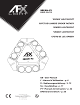
TÉLÉCOMMANDE
1. Marche/Arrêt
2. Mode automatique
3. Modes musicaux
4. Stroboscope
5. Sélection d’un programme intégré
6. Réglage de la sensibilité et de la vitesse en mode musical
7. Réglage de la sensibilité et de la vitesse en mode stroboscope
UTILISATION DE LA TÉLÉCOMMANDE
Utilisez la télécommande à une distance maximale de 6m et un rayon de 30° par
rapport à l’appareil. Pointez la télécommande en direction du capteur. Il ne doit pas y
avoir d’obstacle entre la télécommande et le capteur. La télécommande risque de ne
pas fonctionner lorsque le capteur est soumis à une forte lumière.
Si la télécommande ne fonctionne pas, vériez les piles
INSTALLATION DES PILES
• Placez la télécommande face vers le bas sur une surface plane.
• Poussez le couvercle du compartiment dans le sens de la èche.
• Faites glisser le compartiment de la batterie pour l’ouvrir.
• Retirez l’ancienne pile et installez la nouvelle (CR2032) avec le symbole plus (+) vers le
haut.
• Faites glisser doucement le compartiment à piles pour le fermer. Il se verrouille automatiquement.
RECOMMANDATIONS POUR LES BATTERIES
Ce pictogramme indique que les piles et batteries usagées ne doivent pas être jetées avec les ordures ménagères,
mais déposées dans des points de collecte séparés pour être recyclées. Tenir les piles à l’abri d’une chaleur excessive
telle que le soleil, le feu ou similaires.
Lorsque les piles ne sont pas utilisées, retirez-les pour éviter les dommages causés par des fuites ou la corrosion de la pile.
ATTENTION: Danger d’explosion si la pile n’est pas remplacée correctement. Ne remplacer que par le même type ou un type
équivalent.
AVERTISSEMENT: La télécommande fournie contient une pile bouton. Ne pas ingérer la pile. Danger de brûlure chimique. En
cas de doute concernant le fait que les piles pourraient avoir été avalées ou introduites dans une partie quelconque du corps,
consulter immédiatement un médecin.
Conserver les piles neuves et usées hors de portée des enfants. Si le compartiment à pile ne se ferme pas correctement,
cesser d’utiliser le produit et tenir hors de portée des enfants.
NETTOYAGE DE L’APPAREIL
Nettoyez régulièrement les lentilles et/ou miroirs an d’optimiser la puissance lumineuse. La fréquence de
nettoyage dépend de l’environnement dans lequel l’appareil est utilisé. Un environnement humide, enfumé,
poussiéreux ou particulièrement sale provoque une plus forte accumulation des saletés sur les optiques.
Nettoyez avec un chion doux et du nettoyant à vitres normal.
Séchez toutes les parties soigneusement.
Nettoyez les optiques externes au moins tous les 20 jours. Nettoyez les optiques internes au moins tous les
mois.
CARACTÉRISTIQUES TECHNIQUES:
Alimentation: .................................................................................................................. 100-240V~ 50/60Hz
Consommation ..........................................................................................................................................15W
Canaux ...........................................................................................................................................................8
LED: ...............................................................3 LED RGBW 4W 4-in-1; 18 LED SMD 0.5W blanches 5730LED
Fonction: ................................................................ Automatique, activation par le son, DMX, télécommande
Dimensions: ....................................................................................................................125 x 125 x 125mm
Poids: ....................................................................................................................................................0,6 kg
NOTE IMPORTANTE : Les produits électriques ne doivent pas être mis au rebut avec les ordures ménagères. Veuillez les faire recycler
là où il existe des centres pour cela. Consultez les autorités locales ou votre revendeur sur la façon de les recycler.
1
2
3 3 3
4
5
6
7
PRO LIGHT
SPEED/SEN
SPEED/STROBE

Manual - PAR-MINI-STR
10
©Copyright LOTRONIC 2021
4-IN-1 RGBW LED PAR STRAHLER MIT SMD LED STROBOSKOP
BEDIENUNGSANLEITUNG
ZEICHENERKLÄRUNG
Der Blitz im Dreieck weist auf ein Gesundheitsrisiko hin (z.B. Stromschlag).
Das Ausrufezeichen im Dreieck weist auf besondere Gefahren beim Umgang oder Betrieb des Geräts hin.
Entspricht den Richtlinien der CE
Nur für Innengebrauch
Schutzklasse II: Benötigt keine geerdete Steckdose
0.5m
Mindestentfernung zwischen dem Gerät und anderen Gegenständen
Niemals direkt in den Lichtstrahl blicken
VORSICHT
NICHT DAS GEHÄUSE ÖFFNEN
STROMSCHLAGGEFAHR
SICHERHEITSHINWEISE
Diese Anleitung sorgfältig vor der ersten Inbetriebnahme lesen. Sie enthält wichtige Informationen über Installa-
tion, Gebrauch und Instandhaltung des Geräts.
• Die Anleitung für spätere Bezugnahme aufbewahren und an den nächsten Bediener weitergeben.
• Stets die Netzspannung vor Anschluss des Geräts überprüfen Sie muss mit der auf der Rückseite des Geräts
angegebenen Spannung übereinstimmen und darf auf keinen Fall höher sein.
• Dieses Gerät ist nur für Innengebrauch!
• Um Brand und Stromschlag zu vermeiden, das Gerät vor Regen und Feuchtigkeit schützen. Keine brennbaren
Materialien während des Betriebs in der Nähe des Geräts lassen.
• Das Gerät muss an einem gut belüfteten Ort und in mindestens 50cm Entfernung zur nächsten Fläche ange-
bracht werden. Darauf achten, dass die Belüftungsschlitze nicht blockiert oder verstopft sind.
• Immer erst das Gerät vom Netz trennen, bevor es gewartet oder die Sicherung ersetzt wird. Die Sicherung nur
durch eine identische ersetzen.
• Das Gerät mit einer Sicherheitskette befestigen. Das Gerät niemals nur am Kopf tragen, sondern auch am
Sockel.
• Die Raumtemperatur darf 40°C nicht überschreiten. Das Gerät niemals bei höheren Temperaturen betreiben.
• Bei Betriebsstörungen das Gerät sofort ausschalten. Das Gerät niemals selbst reparieren. Reparaturen dürfen
nur von einem Fachmann vorgenommen werden. Alle verwendeten Ersatzteile müssen mit den Originalteilen
identisch sein.
• Das Gerät nicht an ein Dimmerpack anschließen.
• Das Netzkabel niemals quetschen oder beschädigen.
• Beim Abziehen des Netzsteckers nur am Stecker ziehen, niemals am Kabel.
• Niemals direkt in die Lichtquelle blicken.
• Die Leuchtmittel sind nicht auswechselbar. Wenn sie defekt sind, muss das ganze Gerät entsorgt werden.
• Der Lichte ekt ist nur für dekorative Zwecke und eignet sich nicht als normale Haushaltsbeleuchtung.
Netztrennungsvorrichtungen
a) Wenn das Gerät über den Netzstecker ausgeschaltet wird, muss die Steckdose jederzeit leicht zugänglich
bleiben
b) Wenn das Gerät über einen Schalter ausgeschaltet wird, muss dieser klar gekennzeichnet und leicht zugäng-
lich sein.
INSTALLATION
Das Gerät muss mittels der Schraublöcher am Bügel befestigt werden. Das Gerät darf während des Betriebs
nicht vibrieren oder weggleiten. Achten sie darauf, dass die Struktur, die das Gerät trägt, mindestens 10-mal das
Eigengewicht des Geräts tragen kann.

Manual - PAR-MINI-STR
11
www.ibiza-light.com
DE
Das Gerät muss von einem Fachmann installiert werden. Es muss außerhalb der Reichweite von Personen und
nicht oberhalb von begangenen Wegen installiert werden.
HINTEREINANDERSCHALTEN MEHRERER GERÄTE
Wenn mehrere Geräte über einen DMX Controller gesteuert werden oder zwei und mehr Geräte im Master/Slave
Betrieb arbeiten sollen, wird ein serielles Datenkabel benötigt. Die kombinierte Anzahl von Kanälen, die von
allen Geräten in einer seriellen Datenverbindung benötigt werden, bestimmt die Anzahl von Geräten, die die
Datenverbindung unterstützen kann.
KABELVERBINDER
Die Kabel müssen einen XLR Stecker auf der einen und eine XLR Buchse auf der anderen Seite besitzen.
DMX STECKERBELEGUNG
Der Endwiderstand verringert Signalfehler. Um Signalübertragungsprobleme und
Störungen zu vermeiden, ist es ratsam, einen DMX Signalwiderstand zwischenzu
-
schalten.
ACHTUNG: Der Nullleiter darf nicht mit dem Metallgehäuse des Geräts in Berüh
-
rung kommen, da sonst eine Erdschleife entsteht, die zu Fehlverhalten des Geräts
führt. Testen Sie die Kabel mit einem Ohmmeter, um die Polarität zu prüfen und
sicherzustellen, dass die Stifte nicht geerdet oder kurzgeschlossen sind.
EINRICHTEN EINER SERIELLEN DMX DATENVERBINDUNG
1. Den 3-pol. Stecker des DMX Kabels in die 3-pol. Eingangsbuchse des Controllers stecken.
2. Das vom Controller kommende Kabel mit der 3-pol. Buchse an den 3-pol. Eingangsstecker des folgenden
Geräts stecken.
3. Dann den Ausgang des Geräts an den Eingang des folgenden Geräts anschließen usw.
MASTER/SLAVE ANSCHLUSS
1. Den 3-pol. Stecker des DMX Kabels in die 3-pol. Eingangsbuchse des ersten Geräts stecken.
2. Das vom ersten Gerät kommende Kabel mit der 3-pol. Buchse an den 3-pol. Eingangsstecker des folgenden
Geräts stecken. Dann den Ausgang des Geräts an den Eingang des folgenden Geräts anschließen usw.
MENÜ
Die Funktionen sind über die vier Tasten unterhalb des Displays zugänglich.
Alle Funktionen und Programme können manuell über das Display gesteuert werden, ohne Control
-
ler.
MENU Taste drücken, um ins Menü zu gehen. Die Funktion mit den UP/DOWN Tasten wählen, bzw. den Wert ein
-
stellen und mit der ENTER Taste bestätigen.
Taste Funktion
MENU MENU Taste drücken, um in die Untermenüs zu gehen. Erneut MENU drücken, um weder ins Haupt
-
menü zurück zu gehen. Wenn 30 Sekunden lang keine Taste gedrückt wird, schaltet das Gerät auto-
matisch ins Hauptmenü zurück.
UP Erhöht den angezeigten Wert bzw. aufwärts durch die Liste gehen. Für schnellen Durchlauf gedrückt
halten
DOWN Vermindert den angezeigten Wert bzw. abwärts durch die Liste gehen. Für schnellen Durchlauf ge
-
drückt halten
ENTER Im Hauptmenü hat die Taste keine Funktion. In den Untermenüs gibt sie Zugang zu den Funktionen
und dient zur Bestätigung der Wahl
LCD DISPLAY
MODE MENU FUNKTION
A001~A511 A001~A511 DMX Mode / Jump Strobe
Au**
FF**
Au 1~Au15
Feste Farbe, 1~15 sind die Farbmischungen (Einzelheiten in nachstehender
Tabelle)
FF 1~FF99 Farbwechsel, Wert +, Geschwindigkeit des Farbwechsels +
CC** CC 1~CC99 Farbübergang, Wert +, Geschwindigkeit des Farbwechsels +
EE** EE 1~EE99 Farbimpuls, Wert +, Geschwindigkeit des Farbwechsels +

Manual - PAR-MINI-STR
12
©Copyright LOTRONIC 2021
F***
F001~F009 Kein Stroboskopefect
F010~F255 Wert +, Stroboskopgeschwindigkeit +
AuTo AuTo Automatik, Replay FF**, CC**, EE**, F***
Soud
Soud Musiksteuerung 1
VOL1~VOL9
ENTER drücken "VOL"STROBE, “1~9" ist die Klangempndlichkeit, Wert +,
Empndlichkeit +
AU ** FARBWECHSELTABELLE
Farbe 1 2 3 4 5 6 7 8 9 10 11 12 13 14 15
R ON ON ON ON ON ON ON ON
G ON ON ON ON ON ON ON ON
B ON ON ON ON ON ON ON ON
W ON ON ON ON ON ON ON ON
ON heißt, die Farbe leuchtet, Leere Felder heißt, die Farbe ist ausgeschaltet.
EINSTELLEN DER DMX ADRESSE:
1. MENU Taste drücken, um ins Menü zu gehen. Mit den UP/DOWN Tasten d001 wählen und auf ENTER drücken.
Mit den UP/DOWN Tasten eine Adresse einstellen. ENTER drücken, um die Einstellung zu speichern und das
Menü zu verlassen. Oder auf MENU drücken, um die Funktion ohne Speichern zu verlassen.
2. MENU Taste drücken, um ins Menü zu gehen. Mit den UP/DOWN Tasten eine der verschiedenen Betrieb
-
sarten wählen und auf ENTER drücken, um die Einstellung zu speichern bzw. auf MENU drücken, um das Menü
unverändert zu verlassen.
DMX KANÄLE
KANAL WERT FUNKTION
1 0~255 Master Dimmer
2 0~255 R Dimmer
3 0~255 G Dimmer
4 0~255 B Dimmer
5 0~255 W Dimmer
6
0~255 Wahl der Strobskopfunktion
0~99 Par & Strobe blinken gleichzeitig
100~199 Par Strahler blinkt
200~255 Strobe blinkt
7
0~9 Kein Stroboskopeekt
10~255 Wert +, Stroboskopgeschwindigkeit -
8
0~50 Manueller Betrieb, Kanal 1-Kanal 7
51~100 Farbsprung, wie 'FF**' Betrieb, CH6 regelt die Geschwindigkeit
101~150 Farbsprung, wie 'CC**' Betrieb, CH6 regelt die Geschwindigkeit
151~200 Farbimpuls, wie 'EE**' Betrieb, CH6 regelt die Geschwindigkeit
201~250 Automatik
251~255 Musiksteuerung
Benutzung der Fernbedienung
Die Fernbedienung hat eine Reichweite von 6m in einem Winkel von 30° zum Sensor. Richten Sie sie immer ge
-
nau auf den Sensor. Der Sensor bendet sich auf dem Display. Stellen Sie keine Hindernisse zwischen die Fernbe-
dienung und den Sensor. Wenn sich die Fernbedienung oder der Sensor unter einer starken Lichtquelle benden,
kann die Übertragung gestört sein.
Wenn die Fernbedienung nicht mehr einwandfrei funktioniert, wechseln Sie die Batterie.

Manual - PAR-MINI-STR
13
www.ibiza-light.com
DE
EINSETZEN DER BATTERIE IN DIE FERNBEDIENUNG
• Legen Sie die Fernbedienung mit der Vorderseite nach unten auf eine ebene Fläche.
• Schieben Sie die Abdeckung des Fachs in Pfeilrichtung.
• Schieben Sie das Batteriefach auf.
• Entfernen Sie die alte Batterie und setzen Sie die neue (CR2032) mit dem Pluszeichen (+)
nach oben ein.
• Schieben Sie das Batteriefach vorsichtig zu. Es rastet automatisch ein.
HINWEISE FÜR BATTERIEN IN DER FERNBEDIENUNG
Dieses Symbol weist darauf hin, dass verbrauchte Batterien nicht in den Hausmüll gehören, sondern gemäß den örtlichen Bestimmun-
gen ordnungsgemäß entsorgt werden müssen.
Batterien dürfen nicht übermäßiger Hitze wie Sonnenschein, Feuer oder ähnlichem ausgesetzt werden. Wenn Sie das Gerät eine Weile
nicht benutzen, entfernen Sie die Batterien, um Schäden durch Auslaufen der Batterie oder Korrosion zu vermeiden.
ACHTUNG
Bei falsch eingesetzter Batterie besteht Explosionsgefahr. Batterie nur durch eine gleichwertige ersetzen.
Alte und neue Batterie von Kindern fernhalten. Wenn das Batteriefach nicht richtig schließt, darf das Gerät nicht mehr benutzt und muss
außerhalb der Reichweite von Kindern aufbewahrt werden.
Die mitgelieferte Fernbedienung enthält eine Knopfzelle. Schlucken Sie die Batterien nicht. Verätzungsgefahr. Wenn Sie nicht sicher sind, ob
die Batterien verschluckt oder in einen anderen Körperteil eingeführt wurden, wenden Sie sich sofort an einen Arzt.
FERNBEDIENUNG
1. EIN/AUS
2. Automatikbetrieb
3. Musikgesteuerte Betriebsarten
4. Stroboskop
5. Wahl eines eingebauten Programms
6. Einstellung von Empfindlichkeit und Geschwindigkeit im musikgesteuerten
Betrieb
7. Einstellung von Empfindlichkeit und Geschwindigkeit des Stroboskops
PFLEGE
Regelmäßig die interne und externe Optik/Spiegel reinigen, um die Lichtstärke zu
erhalten. Die Häugkeit hängt von der Betriebsumgebung ab: in einer feuchten,
verrauchten oder besonders schmutzigen Umgebung häuft sich mehr Schmutz
an. Reinigen sie das Gerät mit normalem Glasreiniger.
Alle Teile müssen sorgfältig getrocknet werden.
Die externen Optikteile mindestens alle 3 Wochen reinigen. Die internen optiktei
-
le alle 2-3 Montage reinigen.
TECHNISCHE DATEN:
Betriebsspannung: .......................................................................................................... 100-240V~ 50/60Hz
Verbrauch .................................................................................................................................................15W
Kanäle ............................................................................................................................................................8
Leuchtmittel: ........................................................3 x 4W RGBW LED 4-in-1; 18x 0.5W weiße SMD 5730 LED
Funktion: ...............................................................................Automatik, Klangaktiviert, DMX, Fernbedienung
Abmessungen: ................................................................................................................125 x 125 x 125mm
Gewicht: .................................................................................................................................................0,6kg
WICHTIGER HINWEIS: Elektrogeräte gehören nicht in den Hausmüll. Sie müssen in speziellen Betrieben recycelt werden. Bringen Sie sie
zu einer speziellen Entsorgungsstelle für Elektrokleingeräte (Wertstohof)!
1
2
3 3 3
4
5
6
7
PRO LIGHT
SPEED/SEN
SPEED/STROBE

Manual - PAR-MINI-STR
14
©Copyright LOTRONIC 2021
4-IN-1 RGBW LED PAR CAN MET SMD LED STROBE
HANDLEIDING
VERKLARING VAN DE TEKENS
De bliksem in de driehoek vestigt de aandacht van de gebruiker op een elektrische schok risico.
De driehoek met het uitroepteken vestigt de aandacht van de gebruiker op belangrijke gebruik- of onder-
houdsinstructies.
Voldoet aan de Europese CE richtlijnen
Alleen voor gebruik binnenshuis
Elektrische veiligheidsklasse II - benodigd geen stopcontact met randaarde
0.5m
Minimale afstand tussen het apparaat en andere objecten
Staar niet in de straal
LET OP
NIET DE BEHUIZING OPENEN
GEVAAR VOOR ELECTRISCHE SCHOKKEN
VEILIGHEIDSINSTRUCTIES
Lees de handleiding aandachtig door. Ze bevat belangrijke informaties voor de installatie, gebruik en onderhoud
van dit toestel.
• Bewaar deze handleiding.
• Wees zeker dat u het toestel op de juiste spanning aansluit en dat de lichtnetspanning niet hoger dan de op
de zijde van het toestel aangegeven spanning is.
• Alleen voor gebruik binnenshuis!
• Om vuur en elektrische schokken te verhinderen bescherm het toestel tegen regen en vochtigheid. Wees
zeker dat geen ontvlambare materialen in de buurt van het toestel zijn tijdens de werking.
• Plaats het toestel in een ruimte met voldoende ventilatie en in tenminste 50cm afstand van oppervlakken.
Wees zeker dat de ventilatie openingen niet geblokkeerd zijn.
• Verwijder het stopcontact alvorens u het toestel onderhoud.
• Gebruik het toestel niet in ruimtes met een temperatuur van meer dan 40°C.
• In geval van een ernstig probleem stop het toestel direct. Verzoek nooit het toestel zelfs te repareren. Alle
reparaties moeten van een ervarene technicus doorgevoerd worden. Gebruik alleen onderdelen met dezelfde
speci caties.
• Sluit het toestel niet op een dimmer pack aan.
• Nooit het netsnoer beschadigen of platdrukken.
• Nooit aan de kabel trekken.
• Nooit in de lichtbron kijken.
• De lampen zijn niet vervangbare. Als deze defekt zijn moet het toestel worden weggegooit
• Het product is voor decoratieve doeleinden en niet geschikt als huishoudelijke verlichting
Ontkoppeling van het net: Indien het toestel via een schakelaar wordt uitgeschakeld, moet deze duidelijk
gemarkeerd en gemakkelijk bereikbaar zijn.
AANSLUITEN VAN MEERDERE TOESTELLEN
Indien U meerdere toestellen via een DMX controller of gesynchroniseerde lichtshows in een master/slave modus
wilt sturen hebt U een seriële date kabel nodig. Het gecombineerde aantal van kanalen die alle toestellen in een
seriële verbinding nodig hebben bepaalt de hoeveelheid van toestellen die de data verbinding kan ondersteu-
nen.
INSTALLATIE
Bevestig het toestel via de schroef gaten op de houder. Wees zeker dat het toestel vast geïnstalleerd is om
trillingen en afglijden tijdens de werking te vermijden. Wees zeker dat de truss waaraan u het toestel bevestigd,
stabiel is en 10 keer het gewicht van het toestel kan dragen. Tijdens de montage, gebruik altijd een veiligheids-
kabel dat 12 keer het gewicht kan dragen.

Manual - PAR-MINI-STR
15
www.ibiza-light.com
NL
KABELCONNECTOREN
De kabel moet een XLR stekker op één eind en een XLR contra op het andere eind hebben.
DMX CONNECTOR CONFIGURATIE
De eindweerstand vermindert signaalfouten. Om transmissie problemen en storingen
te voorkomen is het aanbevolen een DMX signaal eindweerstand aan te sluiten.
LET OP
Geen contact maken tussen common en chassis massa. Indien de common op de
massa aangesloten is kan een aardlus ontstaan en het toestel werkt willekeurig. Con
-
troleer de kabels d.m.v. een ohmmeter om de polariteit te controleren en te waarbor-
gen dat de pins niet op aarde aangesloten of met elkaar kortgesloten zijn.
INSTALLATIE VAN EEN DMX SERIËLE DATA LINK
1. Sluit het 3-pin stekkereind van de DMX kabel op de uitgang (3-pin contra) van de controller.
2. Sluit het contra eind van de kabel dat van de controller komt op de ingang (3-pin stekker) van het naaste
toestel aan.
3. Sluit de uitgang van het naaste toestel op de ingang van het volgende toestel aan enz.
MASTER/SLAVE VERBINDING VAN TOESTELLEN
1.Sluit de (male) 3 pin connector eind van de DMX kabel op de 3-pin uitgang (contra) van het eerste toestel aan.
2. Sluit het contra eind van de kabel dat van het eerste toestel komt op de ingang (3-pin stekker) van het naaste
toestel aan.
3. Sluit de uitgang van het naaste toestel op de ingang van het volgende toestel aan enz.
Het is vaak het geval bij master-slave en automatische werking dat het eerste toestel in de rij door instellingen
op de controle paneel of DIP schakelaars moet geïnitieerd worden. De andere toestellen moeten op slave wer
-
king ingesteld worden. Zie het hoofdstuk “Bediening” in deze handleiding om verdere informaties voor installatie
en conguratie te vinden.
BEDIENING
Gebruik de vier knoppen direct beneden het LCD display.
Alle functies en modi kunnen handmatig via de display zonder DMX controller bestuurd worden.
Druk de ENTER toets en kies het menu item via de UP/DOWN toetsen. Druk ENTER om u keuze te bevestigen.
Verhoog of minder de waarde d.m.v. de ENTER toets. Druk op ENTER om te bevestigen en het menu te verlaten.
Toets Functie
MENU Druk MENU om in de sub-menu’s te gaan. Druk opnieuw om het sub-menu te verlaten. Als geduren
-
de 30 seconden geen toets wordt gedrukt, schakelt het toestel automatisch terug naar het hoofd-
menu
UP Verhoogt de getoonde waarde of de lijst naar boven doorlopen
DOWN Vermindert de getoonde waard of de lijst naar beneden doorlopen
ENTER In het hoofdmenu heeft deze toets geen functie. In de sub-menu’s geeft ze toegang in het sub-me
-
nu en bevestigt de keuze
LCD DISPLAY
MODE MENU FUNCTIE
A001~A511 A001~A511 DMX Mode / Jump Strobe
Au**
FF**
Au 1~Au15 Vaste kleur, 1~15 bedoelt kleurenmix ( zie beneden)
FF 1~FF99 Jump Change, waarde +, kleurwisselsnelheid +
CC** CC 1~CC99 Gradual Change, waarde +, kleurwisselsnelheid +
EE** EE 1~EE99 Pulse Change, waarde +, kleurwisselsnelheid +
F*** F001~F009 Geen stroboscoop eect
F010~F255 Waarde +, Stroboscoop snelheid +
AuTo AuTo Auto Mode, Replay FF**, CC**, EE**, F***

Manual - PAR-MINI-STR
16
©Copyright LOTRONIC 2021
Soud
Soud Geluidsbesturing 1
VOL1~VOL9 Druk ENTER "VOL" STROBE, “1~9" bedoelt geluid gevoeligheid, waarde +,
gevoeligheid +
AU ** KLEURWISSELTABEL
Kleur 1 2 3 4 5 6 7 8 9 10 11 12 13 14 15
R ON ON ON ON ON ON ON ON
G ON ON ON ON ON ON ON ON
B ON ON ON ON ON ON ON ON
W ON ON ON ON ON ON ON ON
"ON" bedoelt dat de kleur aangeschakeld is, leeg bedoelt dat de kleur uitgeschakeld is.
INSTELLEN VAN DE DMX CODE
1. Druk op MENU. Kies d001 via de UP/DOWN toetsen en druk ENTER. Stel de waarde d.m.v. de UP/DOWN
toetsen in en bevestig met ENTER of druk de MENU toets om de functie te verlaten.
2. Druk de MENU toets en kies tussen een hoeveelheid van werkingsmodi d.m.v. de UP/DOWN toetsen. Druk op
ENTER om het programma af te spelen of op MENU om de functie zonder wijziging te verlaten.
DMX KANAALTABEL
KANAAL WAARDE FUNCTIE
1 0~255 Master dimmer
2 0~255 R dimmer
3 0~255 G dimmer
4 0~255 B dimmer
5 0~255 W dimmer
6
0~255 Strobe functie
0~99 Par & Strobe itsen tegelijkertijd
100~199 Par Light itsen
200~255 Strobe Light itst
7
0~9 Geen stroboscoopeect
10~255 Waarde +, Stroboscoop snelheid -
8
0~50 Manual Mode, CH1-CH7
51~100 Jump change,zoals 'FF**' mode, CH6 instelling van de snelheid
101~150 Gradual change, zoals 'CC**' mode, CH6 instelling van de snelheid
151~200 Pulse change, zoals 'EE**' mode, CH6 instelling van de snelheid
201~250 Auto Mode
251~255 Geluid besturing
BATTERIJ IN DE AFSTANDSBEDIENING PLAATSEN
• Plaats de afstandsbediening met de voorkant naar beneden op een vlak oppervlak.
• Duw het compartimentdeksel in de richting van de pijl.
• Schuif het batterijvak open.
• Verwijder de oude batterij en plaats de nieuwe (CR2032) met het plusteken (+) naar boven.
• Schuif het batterijvak voorzichtig dicht. Het vergrendelt automatisch.

Manual - PAR-MINI-STR
17
www.ibiza-light.com
NL
AFSTANDSBEDIENING
1. AAN/UIT
2. Automatische werking
3. Geluidsbestuurde werking
4. Stroboscoop
5. Keuze van een ingebouwde programma
6. Instelling van gevoeligheid en snelheid in geluidsgestuurde modus
7. Instelling van gevoeligheid en snelheid van de stroboscoop
GEBRUIK VAN DE AFSTANDSBEDIENING
De afstandsbediening heeft een bereik van 6m in een hoek van 30° ten opzichte
van de ontvanger en moet altijd precies op de ontvanger worden gericht. Nooit
voorwerpen tussen de ontvanger en de afstandsbediening plaatsen. Wanneer
de ontvanger of de afstandsbediening onder een sterke lichtbron staan, kan de
transmissie verstoord worden. Als de transmissie niet langer goed is, de batterij
vervangen.
ADVIES VOOR BATTERIJEN IN DE AFSTANDSBEDIENING
Dit symbool geeft aan dat gebruikte batterijen en accu’s niet bij het huisvuil mogen worden weggegooid, maar moeten worden gede-
poneerd in gescheiden inzamelpunten voor recycling.
WAARSCHUWINGEN VOOR HET GEBRUIK VAN BATTERIJEN
Er is explosiegevaar als de batterij verkeerd is geplaatst. Alleen vervangen door hetzelfde of een vergelijkbaar type. Tegen hitte beschermen.
Bij langere niet-gebruik batterijen uit het vak verwijderen.
Slik de batterij niet in. Gevaar voor chemische brandwonden. Als u twijfelt of de batterijen zijn ingeslikt of in een ander deel van het lichaam
zijn ingebracht, neem dan onmiddellijk contact op met een arts
Houd nieuwe en oude batterijen buiten het bereik van kinderen.
Als het batterijcompartiment niet goed sluit, stop dan met het gebruik van het product en houd het buiten het bereik van kinderen.
REINIGING
Het is belangrijk dat het toestel altijd schoon is om een optimale lichtkracht te garanderen en de leeftijd te
verlengen. De reinigingsfrequentie is afhankelijk van de omgevingsomstandigheden: vochtige, berookte of bi
-
jzonders vuile omgeving veroorzaakt meer vuil op de optische delen.
• Reinig de lamp met een hoogwaardig glasreinigingsmiddel en een zachte doek.
• Droog de delen altijd zorgvuldig.
• Reinig de externe optische delen tenminste alle 20 dagen. Reinig de interne optische delen tenminste alle
30/60 dagen.
SPECIFICATIES:
Aansluitspanning: ........................................................................................................... 100-240V~ 50/60Hz
Opgenomen vermogen .............................................................................................................................15W
Kanalen ..........................................................................................................................................................8
LED: ......................................................................3 x 4W RGBW LED 4-in-1; 18x 0.5W white SMD 5730 LED
Werkingsmodi ..........................................................automatisch, muziek gestuurd, DMX, afstandsbediening
Afmetingen: ....................................................................................................................125 x 125 x 125mm
Gewicht: .................................................................................................................................................0,6kg
BELANGRIJKE OPMERKING De elektrische producten mogen niet naast het huisvuil geplaatst worden. Gelieve deze te laten recycleren
daar waar er centra’s hiervoor voorzien is. Raadpleeg de plaatselijke autoriteiten of uw verkoper ivm de manier van recycleren
1
2
3 3 3
4
5
6
7
PRO LIGHT
SPEED/SEN
SPEED/STROBE

Manual - PAR-MINI-STR
18
©Copyright LOTRONIC 2021
PROYECTOR PAR DE LED RGBW 4-EN-1 CON ESTROBOSCOPIO DE
LED SMD
MANUAL DE USO
EXPLICACIÓN DE LOS SÍMBOLOS
El rayo dentro del triángulo avisa al usuario de la presencia de tensiones no aisladas en el interior del
equipo con una magnitud su ciente para provocar una electrocución.
El punto de exclamación dentro del triángulo avisa al usuario de instrucciones importantes de uso y de
mantenimiento contenidas en la documentación incluida
Conforme con los requisitos de la norma CE
Este producto, es adecuado solo para uso en interiores
Clase de aislamiento II
0.5m
Distancia mínima entre el aparato y otros objetos.
No mires a la viga
ATENCION
NO ABRIR LA CARCASA
PELIGRO DE ELECTROCUCION
INSTRUCCIONES DE SEGURIDAD
Lea atentamente este manual que contiene informaciones importantes de uso y mantenimiento del equipo.
• Conserve este manual para futuras consultas. Si el equipo cambia de propietario, haga llegar este manual al
comprador.
• Asegurese de que la corriente del enchufe corresponde con los requisitos técnicos del equipo indicados en el
mismo.
• Unicamente para su uso en interiores!
• Con el n de evitar cualquier riesgo de incendio o descarga eléctrica, no exponga el equipo a la lluvia o hume-
dad. Asegurese que ningún objeto in amable se encuentra en las proximidades del equipo durante su funcio-
namiento.
• Instale el equipo en un lugar bien ventilado a una distancia mínima de 50 Cm de cualquier super cie. Asegu-
rese de qu las rejillas de ventilación, no quedan bloqueadas.
• Desenchufe el equipo de la corriente antes de cualquier manipulación, limpieza o mantenimiento.
• Asegure el equipo en un dispositoivo de sujección mediante una cadena, sujeta a un punto diferente del lugar
de jación del soporte del equipo. NO traslade el equipo cojiendolo por la carcasa, hágalo cojido por el sopor-
te.
• La temperatura ambiente no puede pasar de los 40°C. No haga funcionar el equipo a temperaturas superio-
res.
• En caso de mal funcionamiento, desenchufe inmediatamente el equipo y llevelo a un servicio técnico cuali-
cado. No intente reparar el equipo por usted mismo, puede producir daños al equipo. Exiga siempre que le
reparan el equipo con piezas originales.
• No enchufe el equipo a un regulador.
• Asegúrese que el cable de corriente no está dañado.
• Jamás desenchufe el equipo, tirando del cable.
• No exponga sus ojos a la fuente luminosa.
• El producto es para nes decorativos y no adecuados como la iluminación de una estancia doméstica
• Cuando el cable de corriente o el interruptor del equipo, sirvan como dispositivo de corte, estos ha de perma-
necer fácilmente accesibles.
• Si un interruptor se utiliza como dispositivo de corte, el lugar en el equipo y la función del interruptor han de
estar descrita y el interruptor ha de permanecer fácilmente accesible
INSTALACIÓN
Fije el equipo con tornillos mediante las escuadras. Asegúrese de que el equipo queda sólidamente jado para
evitar las vibraciones y los movimientos durante su funcionamiento. Compruebe que la estructura que soporta el

Manual - PAR-MINI-STR
19
www.ibiza-light.com
ES
equipo es sucientemente sólida y capaz de aguantar al menos 10 veces el peso del equipo. Utilice, además un
cable de seguridad que aguante 12 veces el peso del equipo, este cable ha de ser jado al equipo y a un punto
diferente de la escuadra de jación.
CONEXIONADO DE MÁS EQUIPOS
Usted necesitara un cable de datos en serie para hacer funcionar más unidades del este equipo mediante una
consola DMX512 o para hacer funcionar dos o más en modo Maestro/Esclavo. El número combinado de canales
requeridos por todos los dispositivos en un cable de datos en serie dene el número de dispositivos que el cable
de datos puede soportar.
CABLEADO
Para conectar los equipos de un conjunto, debe utilizar cables de transmisión de datos. Puede comprar cables
DMX certicados directamente en un vendedor/distribuidor o bien construir sus propios cables. Si desea fabri
-
carlos usted mismo, utilice cables de datos de alta calidad ya que están sujetos a tener menos interferencias
electromagneticas.
CONECTORES DE CABLE
El cable, debe poseer una clavija XLR macho en uno de los extremos y una cla-
vija XLR hembra en el otro.
CONFIGURACIÓN DE LOS CONECTORES DMX
La resistencia de n de línea reduce los errores de señal. Para evitar los proble
-
mas de transmisión de señal, siempre es recomendable conectar una resisten-
cia al nal de la línea DMX.
ATENCION
No debe haber ningun contacto entre el comun y la masa del chasis del equipo. La puesta comun a masa puede
provocar un bucle y hacer que su equipo funcione de un amanera extraña. Compruebe los cables con la ayuda
de un polimetro con el n de vericar la polaridad y asegurarse de que los pines no están conectados a masa,
cortocircuitados con el blindaje o entre ellos.
PUESTA EN MARCHA DE UN ALÍNEA DE DATOS DMX EN SERIE
1. Conecte el lado macho del conector DMX a la salida hembra de la consola DMX.
2. Conecte la otra extremidad del cable a la entrada macho del equipo.
3. Después, conecte la salida del equipo a la entrada del siguiente y así sucesivamente, etc.
MENU
El equipo cuenta con 4 botones para acceder, editar y ajustar todas las funciones.
Todas las funciones y modos, pueden ser controlados manualmente por el Dsiplay, sin necesidad de
controlador DMX.
Apriete la tecla MENU y seleccione el modo de funcionamiento mediante las botones UP/DOWN. Apriete en
ENTER para conrmar la selección. Aumente o disminuya el valor mediante las teclas UP/DOWN. Apriete ENTER
para conrmar y salir del menú.
Tecla Función
MENU Apriete en r MENU para entrar dentro de los sub-menus. Apriete de nuevo para volver al menu
principal. Si no se presiona ninguna tecla durante 30 segundos, el equipo vuelve automáticamente
al menú principal
UP Apriete en UP para aumentar el valor o subir en la lista. Mantener apretado para pasar valores
rápidamente
DOWN Apriete en DOWN para reducirr el valor o bajar en la lista. Mantener apretado para pasar valores
rápidamente
ENTER En el menú principal, ENTER no tiene ninguna función. Dentro de los sub menú, la tecla permite
acceder a los diferentes sub menus

Manual - PAR-MINI-STR
20
©Copyright LOTRONIC 2021
MENÚ
MODO MENU FUNCION
A001~A511 A001~A511 Modo DMX / Estroboscopio
Au**
FF**
Au 1~Au15
Colores jos, 1~15 corresponde a la mezcla de 4 colores (ver el detalle más
abajo)
FF 1~FF99 Cambio total, Valor +, Velocidad de cambio de color +
CC** CC 1~CC99 Cambio progresivo, Valor +, Velocidad de cambio de color +
EE** EE 1~EE99 Cambio a impulsión, Valor +, Velocidad de cambio de color +
F***
F001~F009 Sin efecto estrobo
F010~F255 Valor +, Velocidad de estroboscopio +
AuTo AuTo Modo automático, Replay FF**, CC**, EE**, F***
Soud
Soud Modo controlado por el sonido1
VOL1~VOL9
Apriete en ENTER "VOL"STROBE, “1~9" es el ajuste de la sensibilidad sonora,
Valor +, Sensibilidad +
AU ** TABLA DE CAMBIO DE COLOR
Color 1 2 3 4 5 6 7 8 9 10 11 12 13 14 15
R ON ON ON ON ON ON ON ON
G ON ON ON ON ON ON ON ON
B ON ON ON ON ON ON ON ON
W ON ON ON ON ON ON ON ON
"ON" SIGNIFICA QUE EL COLOR ESTÁ ENCENDIDO, LAS CASILLAS APAGADAS SIGNIFICAN QUE LOS COLORES
ESTÁN APAGADOS.
AJUSTE DE LA DIRECCIÓN DMX:
1. Entre en el menú apretando la tecla MENU. Seleccione D001 mediante las teclas UP/DOWN. Cambie el valor
mediante las teclas UP/DOWN. Apriete en ENTER para guardar o MENU para salir sin guardar.
2. Entre dentro del menú apretando la tecla MENU. Seleccione los diferentes modos de funcionamiento me
-
diante los botones UP/DOWN. Apriete ENTER para grabar o en MENU para salir del menú y volver a los modos
de funcionamiento.
TABLA DE CANALES DMX
Canal Valor Función
1 0~255 Regulador general
2 0~255 Regulador Rojo
3 0~255 Regulador Verde
4 0~255 Regulador Azul
5 0~255 Regulador Blanco
6
0~255 Selección de la función estroboscopio
0~99 Par y Estroboscopio parpadean a la vez
100~199 PAR parpadea
200~255 Estroboscopio parpadea
7
0~9 Sin efecto estroboscopio
10~255 Valor +, Velocidad estroboscopio -
8
0~50 Modo manual, disponible de CH1-CH7
51~100 Cambio repentino, idéntico al modo 'FF**', Ajuste de velocidad canal 6
A página está carregando ...
A página está carregando ...
A página está carregando ...
A página está carregando ...
A página está carregando ...
A página está carregando ...
A página está carregando ...
A página está carregando ...
A página está carregando ...
A página está carregando ...
A página está carregando ...
A página está carregando ...
A página está carregando ...
A página está carregando ...
A página está carregando ...
A página está carregando ...
A página está carregando ...
A página está carregando ...
A página está carregando ...
A página está carregando ...
A página está carregando ...
A página está carregando ...
A página está carregando ...
A página está carregando ...
-
 1
1
-
 2
2
-
 3
3
-
 4
4
-
 5
5
-
 6
6
-
 7
7
-
 8
8
-
 9
9
-
 10
10
-
 11
11
-
 12
12
-
 13
13
-
 14
14
-
 15
15
-
 16
16
-
 17
17
-
 18
18
-
 19
19
-
 20
20
-
 21
21
-
 22
22
-
 23
23
-
 24
24
-
 25
25
-
 26
26
-
 27
27
-
 28
28
-
 29
29
-
 30
30
-
 31
31
-
 32
32
-
 33
33
-
 34
34
-
 35
35
-
 36
36
-
 37
37
-
 38
38
-
 39
39
-
 40
40
-
 41
41
-
 42
42
-
 43
43
-
 44
44


Ibiza Light PAR-MINI-STR Manual do proprietário
- Categoria
- Estroboscópios
- Tipo
- Manual do proprietário
em outros idiomas
- español: Ibiza Light PAR-MINI-STR El manual del propietario
- français: Ibiza Light PAR-MINI-STR Le manuel du propriétaire
- italiano: Ibiza Light PAR-MINI-STR Manuale del proprietario
- Nederlands: Ibiza Light PAR-MINI-STR de handleiding
- Deutsch: Ibiza Light PAR-MINI-STR Bedienungsanleitung
- română: Ibiza Light PAR-MINI-STR Manualul proprietarului
Artigos relacionados
-
 Ibiza Light & Sound PAR-MINI-RGBW Manual do proprietário
-
 Ibiza Light STARBALL-GB Manual do proprietário
-
 Ibiza Light & Sound PAR-MINI-RGB3 Manual do proprietário
-
 Ibiza Light & Sound LMH250WH-MINI Manual do proprietário
-
 Ibiza Light LEDPAR-LAS Manual do proprietário
-
 Ibiza Light & Sound LED-UV24 Manual do proprietário
-
 Ibiza Light & Sound LMH350LED Manual do proprietário
-
 Ibiza Light & Sound 15-1246 Manual do usuário
-
 Ibiza Light & Sound PARLED50-COB Manual do proprietário
-
 Ibiza Light & Sound LMH-MINIWASH Manual do proprietário


Outros documentos
-
JBSYSTEMS LIGHT SUPER SOLAR WHITE Manual do proprietário
-
 afx light 9BEAM-FX Manual do usuário
-
Ibiza LMH-MINIWASH Manual do usuário
-
 HQ Power LEDA03C DMX Controller Output LED Power and Control Unit Manual do usuário
-
 afx light PARCOB50WH Manual do proprietário
-
 afx light LMH460Z-2 Manual do proprietário
-
 LTC Audio LLSCONTROLLER Manual do proprietário
-
Extech Instruments LCR205 Manual do usuário
-
Munters 110468 RHS 4.0.3 Guia de instalação
-
Samsung MRW-TS Manual do usuário


