WEG Analog voltage regulator AVR-A-OPT-03 Manual do usuário
- Tipo
- Manual do usuário

www.weg.net
Analog Voltage Regulator AVR-A-OPT-03 |
1
Motors | Automation | Energy | Transmission & Distribution | Coatings
Analog Voltage Regulator
Regulador de Tensión Analógico
Regulador de Tensão Analógico
AVR-A-OPT-03
AVR-A-OPT-03/B
AVR-A-OPT-03/C
Installation, Operation and Maintenance Manual
Manual de Instalación, Operación y Mantenimiento
Manual de Instalação, Operação e Manutenção


www.weg.net
Analog Voltage Regulator AVR-A-OPT-03 |
3
Installation, Operation and Maintenance Manual.
Manual de Instalación, Operación y Mantenimiento.
Manual de Instalação, Operação e Manutenção.
Document # / Nº do documento: MWML00516
Models / Modelos: AVR-A-OPT-03, AVR-A-OPT-03/B,
AVR-A-OPT-03/C
Language / Idioma: English / Español / Português
Revision / Revisión / Revisão: 04
October / Octubre / Outubro, 2018


www.weg.net
Analog Voltage Regulator AVR-A-OPT-03 |
5
GENERAL INDEX / ÍNDICE GENERAL / ÍNDICE GERAL
Installation, Operation and Maintenance Manual
Page 7 - 30
Manual de Instalación, Operación y Mantenimiento
Páginas 31 - 54
Manual de Instalação, Operação e Manutenção
Páginas 55 - 79
Português
Español
English
Português
Español
English


www.weg.net
Analog Voltage Regulator AVR-A-OPT-03 |
7
FOREWORD
This manual may in no way be reproduced, filed, or transmitted through any type of media, whether it be electronically, by
printing, phonographically or any other audiovisual means without prior consent from WEG. Infringement is subject to
prosecution under the law.
Due to the continuous improvement of WEG products, the present manual may be modified and/or updated without prior
notice which may result in new revisions of the installation and maintenance manuals for the same product.
WEG reserves itself the right not to update automatically the information included in this manual. However, customers may
at any time request any updated version of the manual, which will be supplied to them free of charge.
If requested, WEG can supply an extra copy of this manual. The equipment serial number and model should be informed
by the customer, when making the request.
ATTENTION
1. It is absolutely necessary to follow the procedures contained in this manual for the warranty to be
valid.
2. The alternatorinstallation, operation, and maintenance must be executed by qualified personnel.
NOTES
1. The total or partial reproduction of the information supplied in this manual is authorized, provided
that reference is made to its source;
2. If this manual is lost, an electronic PDF file is available from our website www.weg.net or another
printed copy can be requested.
WEG EQUIPAMENTOS ELÉTRICOS S.A.


www.weg.net
Analog Voltage Regulator AVR-A-OPT-03 |
9
INDEX
1 SAFETY INFORMATION ..................................................................................................... 11
2 STORAGE AND TRANSPORT ............................................................................................ 11
3 INTRODUCTION .................................................................................................................. 11
4 TECHNICAL CHARACTERISTICS ...................................................................................... 12
5 BLOCK DIAGRAM .............................................................................................................. 13
6 IDENTIFICATION STICKER ................................................................................................ 14
7 PROTECTIVE FUSE ............................................................................................................ 14
8 TRIMPOTS FUNCTION ....................................................................................................... 14
9 TRIMPOTS ADJUSTMENT ................................................................................................. 15
10 LED INDICATION ................................................................................................................ 15
11 OPERATION ........................................................................................................................ 15
11.1 VOLTAGE REGULATOR ................................................................................................................ 15
11.2 POWER CIRCUIT CONNECTION ................................................................................................. 15
11.3 VOLTAGE BUILD UP ...................................................................................................................... 15
11.4 PARALLEL OPERATION WITH TWO OR MORE GENERATORS ............................................. 15
12 PROTECTIONS ................................................................................................................... 16
12.1 U/F PROTECTION ........................................................................................................................... 16
12.2 CURRENT LIMITER ......................................................................................................................... 17
13 FIRTS USE .......................................................................................................................... 17
STEPS FOR THE REGULATOR CONNECTION: ...................................................................................... 17
14 CONNECTION FOR AVR-A-OPT-03 AND AVR-A-OPT-03/B ............................................. 18
14.1 CONNECTION WITH AUXILIARY COIL ........................................................................................ 18
14.2 CONNECTION WITHOUT AUXILIARY COIL ................................................................................ 19
15 AVR-A-OPT-03/C CONNECTION ........................................................................................ 20
15.1 CONNECTION WITH AUXILIARY COIL ........................................................................................ 20
15.2 CONNETION WITHOUT AUXILIARY COIL .................................................................................. 21
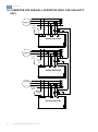
16 CONNETION FOR PARALELL OPERATION (ONLY FOR AVR-A-OPT-03/C) ................... 22
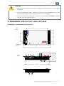
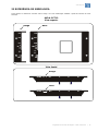
17 DIMENSIONAL (AVR-A-OPT-03 AND AVR-A-OPT-03/B) .................................................. 23
18 TERMINAL CONNECTION .................................................................................................. 24
19 TEST DIAGRAM WITHOUT GENERATOR (AVR-A-OPT-03 / AVR-A-OPT-03/B) .............. 24
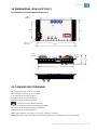
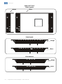
20 DIMENSIONSAL (AVR-A-OPT-03/C) .................................................................................. 25
21 TERMINAL CONNECTION .................................................................................................. 25
22 TEST DIAGRAM WITHOUT ALTERNATOR (AVR-A-OPT-03/C) ..................................... 26
23 REFERENCE OF THE PRINTED SYMBOLS ...................................................................... 27
24 SPECIFICATIONS OF PT FOR POWER SUPPLY .............................................................. 29
25 SPECIFICATION OF PT FOR SENSING VOLTAGE ........................................................... 29
26 SPECIFICATION OF THE CT FOR PARALLELISM ........................................................... 29
27 PREVENTIVE MAINTENANCE ........................................................................................... 29
28 WARRANTY ........................................................................................................................ 29
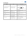
29 TROUBLESHOOT ............................................................................................................... 30


www.weg.net
Analog Voltage Regulator AVR-A-OPT-03 |
11
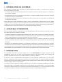
1 SAFETY INFORMATION
To guarantee the safety of the operators, the correct installation and proper operation of the equipment, the following
precautions must be taken:
Installation and maintenance services should be performed only by qualified personnel, using appropriate equipment.;
The product instruction manual and specific product documentation must always be consulted before proceeding with its
installation, handling and parameter setting;
Adequate precautions should be taken to avoid drops, knocks, and/or risks to the operators and the equipment.
Always disconnect the main power supply and wait for the alternatorto come to a complete stop, before touching any
electrical component associated with the equipment including the control connectors. Do not touch the input and output
connectors since high voltages may be present even after the power has been switched off and keep them isolated from
the rest of the principal command circuit of the generator.
2 STORAGE AND TRANSPORT
If the alternatorneeds to be stored for a short period of time before its installation and/or start-up, the following measures
should be taken:
The regulator must remain in its original package or in a similar package which provides the same safety conditions
against mechanical damages, excessive temperature and humidity so as to avoid rusting of contacts and metallic parts,
damages to integrated circuits or any other damage arising from improper storage;
Properly packaged, the regulator must be kept in a dry and well-ventilated area away from direct sunlight, rain, wind and
other adverse weather conditions in order to ensure the preservation of its operational functions.
After the regulator is properly packed and secured in such a way as to absorb shock and vibrations during shipment, the
same will be ready for most means of transportation.
Failure to comply with the above mentioned recommendations could exempt the supplier of the equipment from any
responsibilities and liabilities from any resulting damages, as well as voiding the warranty on the equipment or damaged
part.
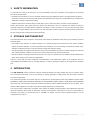
3 INTRODUCTION
The AVR-A-OPT-03 compact electronic Automatic Voltage Regulators are highly reliable and low cost products which
were developed using state of the art technology for voltage regulation of single-phase and three-phase brushless
synchronous generators.
The control and regulation circuit of this AVR uses semiconductors and integrated circuits tested within the highest quality
standards. It doesn’t have mechanical components to start generating and the system is totally static and encapsulated
with epoxy resin, which makes it resistant to maritime environments, able to withstand vibrations of up to 50 mm/s. It has
internal voltage adjustment via trimpot and external voltage adjustment via potentiometer.
The control system is adjusted by one trimpot, which adjusts the stability, making possible a large adjustment range that
allows the operation with all kinds of generators and with several dynamic characteristics. It also has under-frequency
protection (U/F limiter). Its intervention point is adjustable via trimpot, and the nominal operation frequency can be
configured for 50 or 60 Hz.

www.weg.net
l Analog Voltage Regulator AVR-A-OPT-03
12
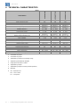
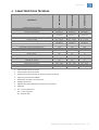
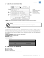
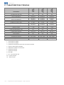
4 TECHNICAL CHARACTERISTICS
Model
Characteristics
AVR
-A-OPT
-03
AVR
-A-OPT
-03/B
AVR
-A-OPT
-03/C
Rated Current
7A
7A
7A
Peak Current (max. 10s)
10A
10A
10A
Power supply (V
al
)
170 - 250Vca
170 - 250Vca
170 - 250Vca
Power supply connection
Single-phase
Single-phase
Single-phase
Sensing Voltage
1
(V
real
)
160-300Vca
320-600Vca
160-300Vca
320-600Vca
160-300Vca
320-600Vca
Sensing Voltage connection
Single-phase
Single-phase
Three-phase
Operation frequency
2
50 / 60Hz
50 / 60Hz
50 / 60Hz
Output voltage
76.5 - 112Vdc
76.5 - 112Vdc
76.5 - 112Vdc
Field resistance (20ºC)
6 - 50
6 - 50
6 - 50
Internal voltage adjustment
3
(%)
160-300Vca
320-600Vca
160-300Vca
320-600Vca
160-300Vca
320-600Vca
External voltage adjustment
4
(%)
Sim / Sí / Yes
Sim / Sí / Yes
Sim / Sí / Yes
Output rectifier gain
5
(K
c
)
0.45
0.45
0.45
Static regulation
0.5%
0.5%
0.5%
Adjustable dynamic answer
8 – 500ms
8 – 500ms
8 – 500ms
Under frequency protection
6
(U/F)
Yes
Yes
Yes
Droop adjust
7
No
No
Yes
External voltage control
- 20% of V
real
- 20% of V
real
- 20% of V
real
Protective fuse
Yes
Yes
Yes
EMI suppression
8
Yes
Yes
Yes
Over field current protection
No
No
Yes
Indicators leds
9
No
OK
OK – Exc - Hz
Operation temperature
-40ºC / +60ºC
-40ºC / +60ºC
-40ºC / +60ºC
Storage temperature
-20ºC / +60ºC
-20ºC / +60ºC
-20ºC / +60ºC
Approximate weight
640g
640g
640g
1. Selectable for jumper
2. Selectable for jumper
3. Adjustable by trimpot for full voltage range
4. Adjusted by potentiometer 5k/3W
5. Single-phase half wave rectifier
6. Adjustable by trimpot
7. Adjustable by trimpot (used for parallel operation)
8. EMI filter
9. OK – Operation OK
Exc – Over current
Hz – Low speed

www.weg.net
Analog Voltage Regulator AVR-A-OPT-03 |
13
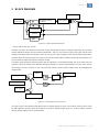
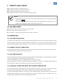
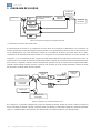
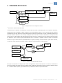
5 BLOCK DIAGRAM
Figure 5.1: Voltage regulator block diagram
1
- Only on AVR-A-OPT-03/C version.
Operation is based in the comparison of the RMS sensing voltage with the reference voltage, adjusted by the sum of the
voltage adjustment trimpots and the external potentiometer. The error is processed by the sensing grid, and this value
determines the firing angle of the thyristor which can vary from 0 to 180, controlling in this way the output voltage of the
generator. With zero degree firing angle, we get zero volt on the rectifier output, and with a firing angle of 180 degrees, we
get the maximum output allowed by the half wave rectifier.
Generation starts through the residual voltage. After the voltage has reached approximately 10% of the rated value, the
regulator controls the voltage of the alternatorcausing the voltage to increase in approximately 1 second, until it reaches
rated voltage. From this moment on, the control grid will maintain constant output voltage of the alternatorwithin the
adjusted value.
Figure 5.2: Control diagram of AVR-A-OPT-03
On Figure 5.2 the control diagram of the AVR-A-OPT-03 voltage regulator is shown. The control is similar to ST1A, shown
by IEEE applied to systems where the rectifier is fed from the alternatoroutput (Type ST - Static Excitation Systems)
directly, through auxiliary coils or per transformer.
Referency
Current limiter
Sensing
Automatic Voltage
Increase
Power Stage
Excitation Field
AlternatorOutput
Sensing Voltage
AlternatorVoltage
U/F Adjust
Alternator Frequency
Error
Signal
Rectifier
Field Voltage

www.weg.net
l Analog Voltage Regulator AVR-A-OPT-03
14
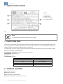
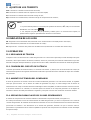
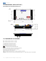
6 IDENTIFICATION STICKER
The example above shows the main characteristics to be observed before installation.
NOTE
1. The identification sticker is located under the regulator.
7 PROTECTIVE FUSE
The fuse is used to limit the power supply input current to protect the alternatorfield. The voltage regulators AVR-A-OPT-
03 are equipped with a controlled rectifier that forces the field voltage to obtain the correct alternatoroutput voltage. When
operating with the maximum field voltage the power input current is
a half of the field current. So, the fuse current must be a little more than the field voltage supported by the voltage regulator.
Some fuse characteristics are listed bellow.
Recommended manufacturer: LittelFuse (ordering code: 235003)
Characteristics: Fast acting fuse.
Dimensions: 5x20 mm.
Current/Voltage: 3A/250V.
8 TRIMPOTS FUNCTION
Vad: Voltage adjustment
Stb: Stability Adjustment
U/F: Under frequency adjustment U/F
Drp: Droop adjustment (only for AVR-A-OPT-03/C)
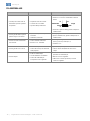
Fuse opening time
% of maximum current
Opening time
110
4 hours (minimum)
135
Max. 1 hour
200
Max 1 second
1- Model
2- Power input
3- Rated current
4- Excitation voltage
5- Operation frequency

www.weg.net
Analog Voltage Regulator AVR-A-OPT-03 |
15
9 TRIMPOTS ADJUSTMENT
Vad = Rotating it clockwise, the voltage increases;
Stb = Rotating it clockwise, the system becomes faster;
U/F = Rotating it clockwise, the U/F range increases;
Drp = Rotating it clockwise, the reactive compensation range increases.
NOTE
1. A potentiometer may be connected for fine voltage adjustment (5 k / 3 W) at terminals identified
by this symbol .
2. The U/F and Stb trimpots were preseted and sealed, but if adjustments are required, They can be
performed according to the procedures described in this manual.
10 LED INDICATION
OK: Regulator OK (For AVR-A-OPT-03/B and AVR-A-OPT-03/C)
Exc: Over current (Only on AVR-A-OPT-03/C)
Hz: Low Rotation – under frequency protection (Only on AVR-A-OPT-03/C)
11 OPERATION
11.1 VOLTAGE REGULATOR
It compares the real voltage value coming from the alternatoroutput with the theoretical value adjusted through the voltage
adjustment trimpot, plus the external voltage adjustment (if available). The error is processed by the sensing stage, which
value determinate the thyristor trigger angle that can vary from 0 to 180°, controlling this way the alternatorvoltage output.
11.2 POWER CIRCUIT CONNECTION
The Voltage that comes from the auxiliary coil is connected to the E3/4 and 3 terminals (or N in version AVR-A-OPT-03/C).
This rectified voltage is applied to the alternatorexciter field.
11.3 VOLTAGE BUILD UP
The residual voltage should start the regulator to build up the output alternatorvoltage. If a low output voltage the regulator
control circuitry supplies the entire power input to the field voltage.
When the output voltage reaches an acceptable value the PI control starts acting.
If the residual voltage is not enough, a field flashing with external batteries is needed. So, the output voltage will build up
enough to supply a voltage to the regulator that will start to control the output voltage.
11.4 PARALLEL OPERATION WITH TWO OR MORE GENERATORS
The reagent compensation system adopted is named phase diagram composition (see Figure 11.1). In this kind of system,
the alternatoroutput voltage signal is taken and the composition with the alternatorcurrent signal it’s made.
The result of this interaction introduces a sensing error in the real voltage signal, causing an increase or decrease in the
alternatorvoltage, keeping the reactive power between the generators (sharing) inside of acceptable values. The
adjustment of this compensation is made by droop adjustment trimpot.

www.weg.net
l Analog Voltage Regulator AVR-A-OPT-03
16
Figure 11.1: Phase diagram
According to the phase diagram, the feedback voltage suffers an influence from the “S” phase current, which is add to the
“R” and “T” phase voltage. The influence is small in module and big in phase, which means that there is a good
compensation for reactive loads and a small influence of active loads.
The current transformer for reactive compensation shall be in “S” phase of the generator, and the sensing signal in “R” and
“T” phases.
To be sure that the compensation is in the correct way, follow the next steps:
a) Start the alternatorin single form (isolate from the current), apply a resistive charge of 20% of its capacity.
b) After turn the droop adjustment trimpot completely clockwise, this process will cause a voltage fall in the generator.
Turning back the trimpot in the anti-clockwise direction, the voltage must increase. If it doesn’t happen, the CT (Current
Transformer) polarity should be inverted. When several machines are connected in parallel, these steps are necessary in
each machine to make sure that all the CT’s are polarized the in the same way.
12 PROTECTIONS
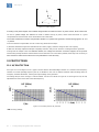
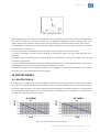
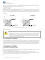
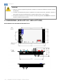
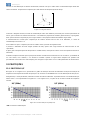
12.1 U/F PROTECTION
On Figure 12.1.a and Figure 12.1.b a graph is shown with the alternatorvoltage variation as a function of the frequency
variation. For rated operating frequency the U/F is disabled. In the case of rotation slowdown (when shutting down, for
example), excitation diminishes, reducing the output voltage of the generator.
The voltage drop is on the average, 0 Volts for 0Hertz. For the case shown on Figure 12.1.a and Figure 12.1.b, the U/F
adjustment was done on the limit of the rated frequency.
U/F (50Hz) U/F (60Hz)
a) b)
Figure 12.1: Actuation point for U/F protection
* UR= Sensing Voltage
F(Hz)
F(Hz)
UR(V)*
UR(V)*

www.weg.net
Analog Voltage Regulator AVR-A-OPT-03 |
17
This operation mode is determined by trimpot U/F, jumper JHz and associated components. The jumper JHz determines
the operation frequency, that follows the logic bellow:
JHz position 1-2 = 50Hz
JHz position 2-3 = 60Hz
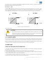
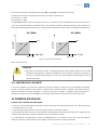
The trimpot U/F determines the actuation point in U/F mode that can be from the rated frequency (Fn) to 1/3 of Fn, which
value comes adjusted by the factory in 10% below Fn. For operation in 60Hz it’s adjusted for 54Hz and for operation in
50Hz it’s adjusted for 45Hz (see Figure 12.2), this value can be changed according to the needs of each application.
U/F (50Hz) U/F (60Hz)
Figure 12.2: Operation of the protection U/F
* Us = Output voltage
ATTENTION
1. Don't let the U/F protection opened. The configuration must be done according Figure 12.2 to avoid
problems when shutting down. The frequency limited by U/F is the frequency of the waveform that
is at the power supply input of the regulator and not at the sensing input.
12.2 CURRENT LIMITER
The current limiter circuit makes the analysis of the field current and compares with a pre-fitted maximum value. When the
current exceeds the maximum value, the limiter reduces the detonation of the thyristor, keeping the power supplied to the
field of the constant generator. While the current is minor than the maximum, the regulator operates normally and the
current limiter remains incapacitated. This protection is present only in AVR-A-OPT-03/C version.
13 FIRTS USE
STEPS FOR THE REGULATOR CONNECTION:
1. Connect the wires coming from the alternatoraccording to the description on items 18 and 21 and the type of alternatorto
be used (item 14, 15, and 16).
2. Before the alternatoris turned on the primary mover should be started and run at rated speed.
3. The alternatorshould start without load. The potentiometer for Voltage adjustment should be configured to the minimum
voltage to avoid alternatorrunaway in case incorrect connections.
4. The potentiometer for stability should be placed in the middle of its course. This potentiometer acts on the dynamic
response of the machine and does not affect the normal permanent operation.
54
Us (Vac)
Un
U/f
60
F (Hz)
45
Us (Vac)*
Un
U/f
50
F (Hz)

www.weg.net
l Analog Voltage Regulator AVR-A-OPT-03
18
5. The Potentiometer for adjustment of the U/F protection should be maintained with the factory configuration since all units
are tested and configured before leaving the factory. If there are problems starting the alternatorwith U/F actuated, it can
be configured during operation.
6. Turn on the start key. Field flashing should take less than 3 seconds. If there is not field flashing or if the fuse blows,
consult item 28 before contacting the manufacturer.
7. After starting, regulate stability Potentiometer, applying and taking out load until reaching the point where voltage does
not oscillate (or has lowest oscillation) with load variation.
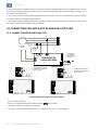
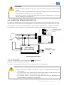
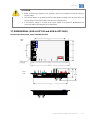
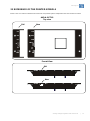
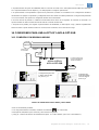
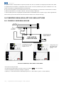
14 CONNECTION FOR AVR-A-OPT-03 AND AVR-A-OPT-03/B
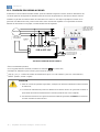
14.1 CONNECTION WITH AUXILIARY COIL
Sensing Voltage 160 to 300Vac and 320 to 600Vac.
¹ Item not supplied by WEG;
² If there is no Potentiometer connected, keep terminals short-circuited;
³ 10A/250Vac switch to turn ON/OFF the regulator;
4
JR Jumper – Sensing voltage selection (pins 1-2 = 160 to 300Vac, pins 2-3 = 320 to 600Vac).
GERADOR
GENERADOR
GENERATOR
BOBINA AUXILIAR
BOBINA AUXILIAR
AUXILIARY COIL
EXCITER FIELD
CAMPO DE LA EXCITATRIZ
CAMPO DA EXCITATRIZ
ON/OFF SWITCH
LLAVE LIG./DESL.
CHAVE LIG./DESL.
POTENCIOMETRO DE AJUSTE
EXTERNO DE TENSÃO (5k /3W)
EXTERNO DE TENSION (5k /3W)
POTENCIOMETRO DE AJUSTE
EXTERNAL ADJUSTMENT
POTENTIOMETER (5k /3W)
WRGA-01
WRGA-01/B
OK
JR
OK
JR
U/F
Stb
Vad
JHz
OK
JR
U/F
Stb
Vad
JHz
OK
JR
EXCITER
FIELD
ON/OFF
SWITCH
AUXILIARY
COIL³
EXTERNAL
ADJUSTMENT
POTENTIOMETER
(5k/3W) ¹ ²
Configuration for 160
to 320V use jump on
pins 1 and 2
4
Configuration for 320
to 600V use jumper on
pins 2 and 3
4
AVR-A-OPT-03
AVR-A-OPT-03/B

www.weg.net
Analog Voltage Regulator AVR-A-OPT-03 |
19
GERADOR
GENERADOR
GENERATOR
EXCITER FIELD
CAMPO DE LA EXCITATRIZ
CAMPO DA EXCITATRIZ
ON/OFF SWITCH
LLAVE LIG./DESL.
CHAVE LIG./DESL.
WRGA-01
WRGA-01/B
POTENCIOMETRO DE AJUSTE
EXTERNO DE TENSÃO (5k /3W)
EXTERNO DE TENSION (5k /3W)
POTENCIOMETRO DE AJUSTE
EXTERNAL ADJUSTMENT
POTENTIOMETER (5k /3W)
ATTENTION
1. Before connecting the regulator to the generator, verify in the installation manual, the reference nominal
voltage.
2. The sensing voltage can be different than the alternatorphase voltage. Note the point where the sensing
voltage is taken from (middle of the phase or complete phase).
3. If the reference voltage is not equal to the output voltage of the generator, do not make the connections
without consulting the service department.
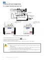
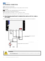
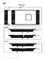
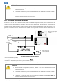
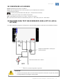
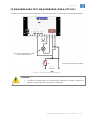
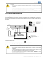
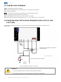
14.2 CONNECTION WITHOUT AUXILIARY COIL
The connection diagram below can only be used when there is not an auxiliary coil present and where the power for the
regulator power circuit is obtained from the alternatorphases. The voltage between pins 3 and E3/4 should be in the range
of 170 to 250 Vac. See below a connection example in a 220 Vac phase to phase generator. For regulator connections in
a alternatorwith a different voltage than what is mentioned in the example, please contact the regulator manufacturer.
Sensing Voltage 160 to 300Vac
¹ Item not supplied by WEG;
² If there is no Potentiometer connected, keep terminals short-circuited;
³ 10A/250Vac switch to turn ON/OFF the regulator;
4
JR Jumper – Sensing voltage selection (pins 1-2 = 160 to 300Vac, pins 2-3 = 320 to 600Vac).
ATTENTION
1. Before connecting the regulator to the generator, verify in the installation manual, the reference
nominal voltage.
2. The sensing voltage can be different than the alternatorphase voltage. Note the point where the
sensing voltage is taken from (middle of the phase or complete phase).
3. If the reference voltage is not equal to the output voltage of the generator, do not make the
connections without consulting the service department.
OK
JR
U/F
Stb
Vad
JHz
OK
JR
ON/OFF
SWITCH
EXCITER
FIELD
EXTERNAL ADJUSTAMENT
POTENTIOMETER (5k/3W) ¹ ²
Configuration for 160 to
320V use jump on pins
1 and 2
4
AVR-A-OPT-03
AVR-A-OPT-03/B

www.weg.net
l Analog Voltage Regulator AVR-A-OPT-03
20
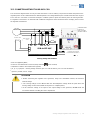
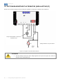
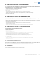
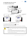
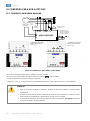
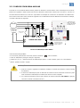
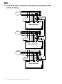
15 AVR-A-OPT-03/C CONNECTION
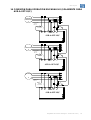
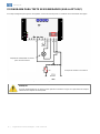
15.1 CONNECTION WITH AUXILIARY COIL
Sensing Voltage 160 to 300Vac and 320 to 600Vac.
¹ Item not supplied by WEG (opened – parallel, closed – single);
² If there is no Potentiometer connected, keep terminals short-circuited;
³ 10A/250Vac switch to turn ON/OFF the regulator;
4
JR, JS e JT Jumpers – Sensing voltage selection (pins 1-2 = 160 to 300Vac, pins 2-3 = 320 to 600Vac).
ATTENTION
1. Before connecting the regulator to the generator, verify in the installation manual, the reference
nominal voltage.
2. The sensing voltage can be different than the alternatorphase voltage. Note the point where the
sensing voltage is taken from (middle of the phase or complete phase).
3. If the reference voltage is not equal to the output voltage of the generator, do not make the
connections without consulting the service department.
GERADOR
GENERADOR
GENERATOR
3
N
R
F+
F-
BOBINA AUXILIAR
BOBINA AUXILIAR
AUXILIARY COIL
EXCITER FIELD
CAMPO DE LA EXCITATRIZ
CAMPO DA EXCITATRIZ
ON/OFF SWITCH
LLAVE LIG./DESL.
CHAVE LIG./DESL.
WRGA-01/C
S
T
P1
P2
S1 S2
2
1
CHAVE SINGELO / PARALELO
LLAVE SINGELO / PARALELO
SINGLE / PARALLEL SWITCH
POTENCIOMETRO DE AJUSTE
EXTERNO DE TENSÃO (5k /3W)
EXTERNO DE TENSION (5k /3W)
POTENCIOMETRO DE AJUSTE
EXTERNAL ADJUSTMENT
POTENTIOMETER (5k /3W)
JR
JS
JT
JHz
JR
JS
JT
Drp
U/F
Vad
Stb
OK
Exc
U/F
U/F
Vad
Stb
Drp
JHz
JR
JS
JT
JR
JS
JT
S1
S2
ON/OFF
SWITCH
EXCITER FIELD
AUXILIARY
COIL³
SINGLE/PARALLEL
SWITCH ¹
EXTERNAL ADJUSTMENT
POTENTIOMETER
(5k/3W) ¹ ²
Configuration for 160 to
320V use jump on pins
1 and 2
4
Configuration for 320 to
600V use jumper on pins
2 and 3
4
AVR-A-OPT-03/C
A página está carregando...
A página está carregando...
A página está carregando...
A página está carregando...
A página está carregando...
A página está carregando...
A página está carregando...
A página está carregando...
A página está carregando...
A página está carregando...
A página está carregando...
A página está carregando...
A página está carregando...
A página está carregando...
A página está carregando...
A página está carregando...
A página está carregando...
A página está carregando...
A página está carregando...
A página está carregando...
A página está carregando...
A página está carregando...
A página está carregando...
A página está carregando...
A página está carregando...
A página está carregando...
A página está carregando...
A página está carregando...
A página está carregando...
A página está carregando...
A página está carregando...
A página está carregando...
A página está carregando...
A página está carregando...
A página está carregando...
A página está carregando...
A página está carregando...
A página está carregando...
A página está carregando...
A página está carregando...
A página está carregando...
A página está carregando...
A página está carregando...
A página está carregando...
A página está carregando...
A página está carregando...
A página está carregando...
A página está carregando...
A página está carregando...
A página está carregando...
A página está carregando...
A página está carregando...
A página está carregando...
A página está carregando...
A página está carregando...
A página está carregando...
A página está carregando...
A página está carregando...
A página está carregando...
-
 1
1
-
 2
2
-
 3
3
-
 4
4
-
 5
5
-
 6
6
-
 7
7
-
 8
8
-
 9
9
-
 10
10
-
 11
11
-
 12
12
-
 13
13
-
 14
14
-
 15
15
-
 16
16
-
 17
17
-
 18
18
-
 19
19
-
 20
20
-
 21
21
-
 22
22
-
 23
23
-
 24
24
-
 25
25
-
 26
26
-
 27
27
-
 28
28
-
 29
29
-
 30
30
-
 31
31
-
 32
32
-
 33
33
-
 34
34
-
 35
35
-
 36
36
-
 37
37
-
 38
38
-
 39
39
-
 40
40
-
 41
41
-
 42
42
-
 43
43
-
 44
44
-
 45
45
-
 46
46
-
 47
47
-
 48
48
-
 49
49
-
 50
50
-
 51
51
-
 52
52
-
 53
53
-
 54
54
-
 55
55
-
 56
56
-
 57
57
-
 58
58
-
 59
59
-
 60
60
-
 61
61
-
 62
62
-
 63
63
-
 64
64
-
 65
65
-
 66
66
-
 67
67
-
 68
68
-
 69
69
-
 70
70
-
 71
71
-
 72
72
-
 73
73
-
 74
74
-
 75
75
-
 76
76
-
 77
77
-
 78
78
-
 79
79


WEG Analog voltage regulator AVR-A-OPT-03 Manual do usuário
- Tipo
- Manual do usuário
em outras línguas
Artigos relacionados
-
WEG Automatic Voltage Regulator AVR-A-OPT-16 Manual do usuário
-
-
-
-
-
-
-
-
-