
Motors | Automation | Energy | Transmission & Distribution | Coatings
Automatic Voltage Regulator
Regulador Automático de Tensión
Regulador Automático de Tensão
AVR-A-OPT-04E
AVR-A-OPT-05PE
Installation, Operation and Maintenance Manual
Manual de Instalación, Operación y Mantenimiento
Manual de Instalação, Operação e Manutenção


Installation, Operation and Maintenance Manual
Manual de Instalación, Operación y Mantenimiento
Manual de Instalação, Operação e Manutenção
Document # / Nº do documento: MWML00512
Models / Modelos: AVR-A-OPT-04E, AVR-A-OPT-05PE
Language / Idioma: English / Español / Português
Revision / Revisión / Revisão: 04
October / Octubre / Outubro, 2017


GENERAL INDEX / ÍNDICE GENERAL / ÍNDICE GERAL
Installation, Operation and Maintenance Manual
Page 7 - 20
Manual de Instalación, Operación y Mantenimiento
Páginas 21 - 34
Manual de Instalação, Operação e Manutenção
Páginas 35 - 51
Português Español English


www.weg.net
Automatic Voltage Regulator – AVR-A-OPT-04E / AVR-A-OPT-05PE l 7
FOREWORD
This manual may in no way be reproduced, filed or transmitted through any type of media, whether
it be electronically, by printing, phonographically or any other audiovisual means without prior
consent from WEG. Infringement is subject to prosecution under the law.
Due to the continuous improvement of WEG products, the present manual may be modified and/or
updated without prior notice which may result in new revisions of the installation and maintenance
manuals for the same product.
WEG reserves itself the right not to update automatically the information included in this manual.
However, customers may at any time request any updated version of the manual, which will be
supplied to them free of charge.
If requested, WEG can supply an extra copy of this manual. The equipment serial number and
model should be informed by the customer, when making the request.
ATTENTION
1. It is absolutely necessary to follow the procedures contained in this manual for the warranty to be valid.
2. The alternator installation, operation and maintenance must be executed by qualified personnel.
NOTES
1. The total or partial reproduction of the information supplied in this manual is authorized, provided that
reference is made to its source;
2. If this manual is lost, an electronic PDF file is available from our website www.weg.net or another
printed copy can be requested.


www.weg.net
Automatic Voltage Regulator – AVR-A-OPT-04E / AVR-A-OPT-05PE l 9
INDEX
1 SAFETY INFORMATION .............................................................................................. 11
2 STORAGE INFORMATION .......................................................................................... 11
3 INTRODUCTION ........................................................................................................... 11
4 TECHNICAL CHARACTERISTICS .............................................................................. 12
5 REGULATOR NAMEPLATE ........................................................................................ 12
6 BLOCK DIAGRAM ....................................................................................................... 13
7 TRIMPOTS FUNCTION ................................................................................................ 13
8 TRIMPOTS ADJUSTMENT .......................................................................................... 13
9 OPERATION ................................................................................................................. 14
9.1 VOLTAGE REGULATOR .................................................................................................................. 14
9.2 POWER CIRCUIT CONNECTION .................................................................................................... 14
9.3 FIELD FLASHING ............................................................................................................................. 14
9.4 U/F OPERATION .............................................................................................................................. 14
9.5 PARALLEL OPERATION FOR TWO OR MORE ALTERNATORS ................................................... 15
10 CONNECTION DIAGRAMS .......................................................................................... 16
10.1 CONNECTION FOR ALTERNATOR WITHOUT AUXILIARY COIL .................................................. 16
10.2 CONNECTION FOR ALTERNATOR FITTED WITH AUXILIARY COIL ............................................ 17
11 DIMENSIONAL DRAWINGS (MM) ............................................................................... 18
12 IDENTIFICATION OF CONNECTION TERMINALS ..................................................... 18
13 DIAGRAM FOR TEST WITHOUT ALTERNATOR ....................................................... 18
14 PROBLEMS, CAUSES AND CORRECTIVE ACTIONS ............................................... 20
15 PREVENTIVE MAINTENANCE .................................................................................... 20
16 WARRANTY ................................................................................................................. 20


www.weg.net
Automatic Voltage Regulator – AVR-A-OPT-04E / AVR-A-OPT-05PE l 11
1 SAFETY INFORMATION
To guarantee the safety of the operators, the correct installation and proper operation of the equipment, the following
precautions must be taken:
Installation and maintenance services should be performed only by qualified personnel, using appropriate equipment;
The product instruction manual and specific product documentation must always be consulted before proceeding with
its installation, handling and parameter setting;
Adequate precautions should be taken to avoid drops, knocks and/or risks to the operators and the equipment.
Always disconnect the main power supply and wait for the alternator to come to a complete stop, before touching any
electrical component associated with the equipment including the control connectors. Do not touch the input and output
connectors since high voltages may be present even after the power has been switched off and keep them isolated from
the rest of the main command circuit of the alternator.
2 STORAGE INFORMATION
If the alternator needs to be stored for a short period of time before its installation and/or start-up, the following measures
should be taken:
The regulator must remain in its original package or in a similar package which provides the same safety conditions
against mechanical damages, excessive temperature and humidity so as to avoid rusting of contacts and metallic parts,
damages to integrated circuits or any other damage arising from improper storage;
Properly packaged, the regulator must be kept in a dry and well-ventilated area away from direct sunlight, rain, wind
and other adverse weather conditions in order to ensure the preservation of its operational functions.
Failure to comply with the above mentioned recommendations could exempt the supplier of the equipment from any
responsibilities and liabilities from any resulting damages as well as voiding the warranty on the equipment or damaged
part.
3 INTRODUCTION
The AVR-A-OPT automatic analog voltage regulators are compact while featuring high reliability and low cost. They were
designed with state-of-the-art technology for voltage regulation of brushless synchronous alternators.
Their control and regulation circuits use semiconductors and integrated circuits duly tested following the most demanding
quality requirements. Mechanical components for field flashing are not required, and its system is completely solid state
and encapsulated in epoxy resin suitable for maritime environments and able to withstand vibrations of up to 50 mm/s. It
is fitted with internal voltage adjustment by trimpot and external by potentiometer allowing a alternantor voltage
adjustment.
The PID control system is adjusted with two trimpots that adjust the proportional gain and the integral gain allowing a
wide adjustment range while allowing operation of the regulator with several types of alternators, and with a high number
of dynamic characteristics. The under frequency protection set point is adjustable by trimpot, and the nominal operating
frequency can be set to 50Hz or 60Hz.

www.weg.net
12 l Automatic Voltage Regulator – AVR-A-OPT-04E / AVR-A-OPT-05PE
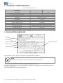
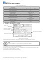
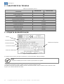
4 TECHNICAL CHARACTERISTICS
Table 4.1: Technical characteristics
Model
Characteristics
AVR-A-OPT-04E AVR-A-OPT-05PE
Nominal operating current 5A 7A
Peak Current 7A 10A
Analog input ±9Vdc Yes
Droop adjustment for parallel operation Yes
CSA certification Yes
Sensing Input 160-300 Vac or 320-600 Vac (Vsen)
Power supply
170-300 Vac (1
∅
or 2
∅
)
Rectifier gain ratio 0,45
Output voltage¹ 76,5-126 Vdc
Field resistance @ 20ºC 6 up to 50Ω
Static regulation 0,5%
Adjustable dynamic response 8 up to 500ms
Operating frequency 50 or 60Hz
Under Frequency protection (U/F) Adjustable
Internal voltage adjustment Adjustable via trimpot, for the complete range of Voltage
External voltage adjustment² - 30% (Vsen)
Operating Temperature -20° to +60ºC
EMI suppression EMI Filter
Approximate weight 480 g
5 REGULATOR NAMEPLATE
The example above shows the main characteristics to be followed before installation.
NOTE
The identification nameplate is attached to the bottom of the regulator frame.
¹ For an input voltage of 170Vac, the maximum output voltage obtained is 76.5Vdc.
For 280Vac of input voltage, the output voltage obtained is 126Vdc, that is, the maximum dc output voltage is equal to
0.45 x the ac voltage input.
² Recommended the use of multi-turn potentiometer.
Figure 5.1: Regulator Nameplate
Operating Frequency
Model
Power Supply
Excitation Voltage
Rated Current
Sensing Voltage

www.weg.net
Automatic Voltage Regulator – AVR-A-OPT-04E / AVR-A-OPT-05PE l 13
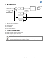
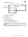
6 BLOCK DIAGRAM
Figure 6.1: Block diagram
7 TRIMPOTS FUNCTION
P1: Voltage adjustment
P2: Droop adjustment.
P3: Stability - 2 adjustment.
P4: Stability - 1 adjustment.
P5: Under frequency adjustment.
8 TRIMPOTS ADJUSTMENT
P1: Rotating CW, voltage increases.
P2: Rotating CW, reactive compensation range increases.
P3: Rotating CW, dynamic response will be slower.
P4: Rotating CW, dynamic response will be slower.
P5: Rotating CW, U/F range increases and rotating CCW, it decreases.
NOTE
* A potentiometer may be connected for fine voltage adjustment (5 kΩ / 3 W) at terminals 6 and 7.
* The P3, P4 and P5 trimpots were preseted and sealed, but if adjustments are required, They can be
performed according to the procedures described in this manual.
Power stage
G
U/F
DROOP
+
+
-
+
Analog input
± 9 Vdc
Reference value
Excitation field
Automatic
field flashing
PID
Sensing
www.weg.net
14 l Automatic Voltage Regulator – AVR-A-OPT-04E / AVR-A-OPT-05PE
9 OPERATION
9.1 VOLTAGE REGULATOR
It compares the actual output voltage from the alternator with the theoretical adjusted value through the trimpot of voltage
adjustment P1, plus the external voltage adjustment (if any). The error is processed by the sensing loop whose value
determines the thyristor firing angle which may vary from 0 to 180°, thus controlling the output voltage of the alternator.
9.2 POWER CIRCUIT CONNECTION
The alternator voltage or the auxiliary winding voltage is connected to the terminals 3 and E3/4. This rectified voltage is
applied, in a controlled fashion, to the alternator exciter field.
9.3 FIELD FLASHING
Generation begins through the residual voltage of the alternator. Once the voltage has reached about 10% of the nominal
voltage, the regulator controls the alternator voltage causing it to rise through the initial ramp in approximately 3 seconds.
When the alternator reaches its nominal value, the PID control loop will maintain the alternator output voltage constant
within the adjusted value.
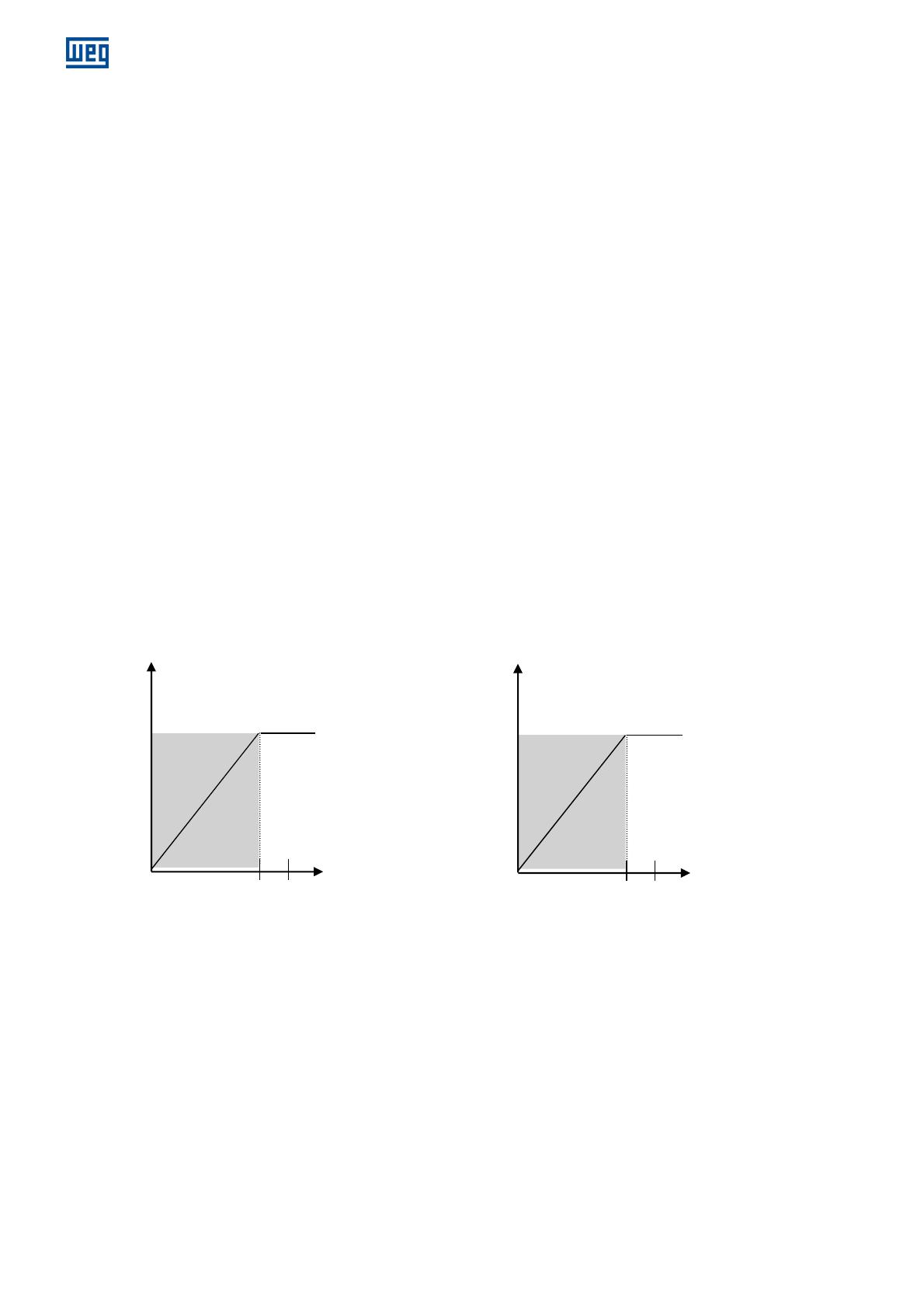
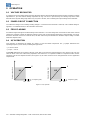
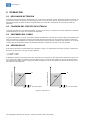
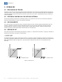
9.4 U/F OPERATION
This operation is determined by trimpot P5, jumper J1 and associated components. The J1 jumper determines the
operating frequency (50 or 60 Hz), following the logic below:
J1 closed = 60 Hz
J1 open = 50 Hz
Trimpot P5 determines the set point of the U/F mode, that can be from the nominal frequency (Fn) down to 1/3 of Fn, the
value of which comes out of the factory adjusted to 10% below Fn. For operation at 60Hz it is adjusted to 54Hz and for
operation at 50 Hz it is adjusted to 45Hz (see Figure 9.1), the value of which can be changed based on each application
requirements.
Figure 9.1: U/F operation
Output voltage (Vac)
Frequency (Hz)
Output voltage (Vac)
Frequency (Hz)
45
U
U/f
50
54
U
U/f
60

www.weg.net
Automatic Voltage Regulator – AVR-A-OPT-04E / AVR-A-OPT-05PE l 15
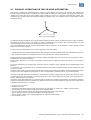
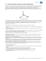
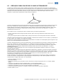
9.5 PARALLEL OPERATION FOR TWO OR MORE ALTERNATORS
The reactive compensation method applied is called a phasor diagram (see Figure 9.2). Through this diagram, the
alternator output voltage signal is measured and compared with the alternator current voltage. The result of this interaction
introduces a sensing error of the actual voltage signal, causing an increase or a decrease in the alternator voltage, thus
maintaining the reactive between the alternators within acceptable values. The adjustment of this compensation is made
through trimpot P2.
Figure 9.2: Phasorial diagram
According to the phasor diagram, the sensing voltage is influenced by the current coming from phase S, which is added to
the voltage of phases R and T. The influence is small in module and large in phase, which means that there is good
compensation for reactive loads and a small influence with active loads.
The current transformer (CT) for reactive compensation must be in phase S of the alternator, and the voltage sensing
signal must be in phases R and T.
To make sure the compensation is in the proper direction, proceed as follows:
Operate the alternator by itself (isolated from the grid) and apply a resistive load with about 20% of the alternator capacity;
After completely rotating the P2 trimpot clock wise (CW), the alternator voltage should decrease.
Rotating back the trimpot completely CCW, alternator voltage should then increase; If this occurs, the CT polarity is correct.
Otherwise the CT should be inverted.
When several alternators are connected in parallel, this procedure is required to ensure that all the CT’s are properly
polarized.
The current transformer for compensation of reactive must be in phase S of the alternator and the feeding signal in the
phase R.
To ensure the correct polarization of TC, Inductive Resistive loads must be applied and the system checked for good
response as below.
Resistive Loads: It will not present compensation with resistive load, keeping the excitation current and alternator voltage
constant in the value adjusted via trimpot Vad. In case of compensation, it indicates that TC is in the wrong phase.
Inductive Loads: With inductive load application, it shall present negative compensation, decreasing the excitation current
corresponding to the gain adjusted in the trimpot droop (0 to 15% voltage adjusted in the Vad). If the compensation is
positive, it indicates the TC is inverted.
Capacitive Loads: With application of capacitive loads, it will present a positive compensation, increasing the excitation
current corresponding to the gain adjusted in the trimpot droop (0 to 15% voltage adjusted in the Vad). If the compensation
is positive, it indicates the TC is inverted.
Accuracy class of 0,6C12,5;
Window or bar type;
Transformer ratio will be In/5A or In/1A, where In/xA is the ratio of the TC primary. Ex.: 100/5A, 150/5A, 100/1A;
5A secondary current for regulator PAR/5 and 1A for regulator PAR/1;
The current in TC primary must be 20% bigger than the nominal current of the machine;
The TC operation frequency must be equal to the alternator frequency;
The TC isolation voltage class must be bigger than the alternator output voltage;
It must support 1.2 x In.
RT
R
T
IS
S

www.weg.net
16 l Automatic Voltage Regulator – AVR-A-OPT-04E / AVR-A-OPT-05PE
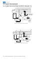
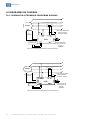
10 CONNECTION DIAGRAMS
10.1 CONNECTION FOR ALTERNATOR WITHOUT AUXILIARY COIL
Figure 10.1: Sensing Voltage of 160 up to 300Vac
Figure 10.2: Sensing Voltage of 320 up to 600Vac
N
R
S
T
Parallelism CT ratio In/5A¹
Exciter
field
F-
F+
Alternator
Potentiometer
for external
voltage
regulation¹ ²
(5kΩ/3W)
AVR
F+
F-
E1
E2
3
7
6
Single/parallel switch¹
Open: parallel;
Closed: single
1
2
P1
P2
S1
S2
E
3/4
J1
A
B
Input ± 9V
- +
N
R
S
T
Parallelism CT ratio In/5A¹
Exciter
field
F
-
F+
Potentiometer for
external voltage
regulation¹ ²
(5kΩ/3W)
AVR
F+
F-
7
6
Single/parallel
switch¹
Open: parallel;
Closed: single
1
2
P1
P2
S1
S2
J1
A
B
Input ± 9V
-
+
Alternator
E1
E2
3
E
3/4

www.weg.net
Automatic Voltage Regulator – AVR-A-OPT-04E / AVR-A-OPT-05PE l 17
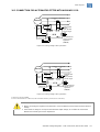
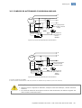
10.2 CONNECTION FOR ALTERNATOR FITTED WITH AUXILIARY COIL
Figure 10.3: Sensing Voltage of 160 up to 300Vac
Figure 10.4: Sensing Voltage of 320 up to 600Vac
1 ITEM NOT SUPPLIED BY WEG.
2 IF NO POTENTIOMETER IS CONNECTED, KEEP TERMINALS 6 AND 7 JUMPED (SHORT-CIRCUITED).
ATTENTION
1. Before connecting the regulator to the alternator, check installation manual and the nominal reference
voltage;
2. If the reference voltage is not equal to the alternator output voltage, do not make the connections
without first contacting the service department.
N
R
S
T
Parallelism CT ratio In/5A¹
Exciter
field
F- F+
Potentiometer for
external voltage
regulation¹ ²
(5kΩ/3W)
AVR
F+
F-
7
6
Single/parallel
switch¹
Open: parallel;
Closed: single
1
2
J1
A
B
Input ± 9V
-
+
N
R
S
T
Parallelism CT ratio In/5A¹
Exciter
field
F
-
F+
Potentiometer for
external voltage
regulation¹ ²
(5kΩ/3W)
AVR
F+
F-
E1
E2
3
7
6
Single/parallel
switch¹
Open: parallel;
Closed: single
1
2
P1
P2
S1
S2
E
3/4
J1
A
B
Input ± 9V
-
+
Aux
Coil
Alternator
Alternator
Aux
Coil
E1
E2
3
E
3/4
P1
P2
S1
S2

www.weg.net
18 l Automatic Voltage Regulator – AVR-A-OPT-04E / AVR-A-OPT-05PE
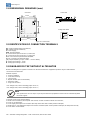
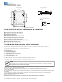
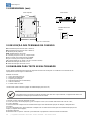
11 DIMENSIONAL DRAWINGS (mm)
Figure 11.1: Dimensional
12 IDENTIFICATION OF CONNECTION TERMINALS
E1: Sensing Voltage (160 up to 300Vac);
E2: Voltage (320 up to 600Vca);
3: Power supply;
E3/4: Sensing Voltage;
1: Connection for pole S1 of the CT, ratio In/5A;
2: Connection for pole S2 of the CT, ratio In/5A;
6 e 7: Connection for potentiometer 5KΩ/3W;
F+, F-: Connection for alternator field;
J1: Jumper 50/60Hz (J1 open = 50Hz – closed = 60Hz);
A: Analog input voltage – 9 Vdc;
B: Analog input voltage + 9 Vdc.
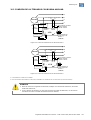
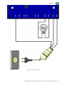
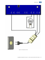
13 DIAGRAM FOR TEST WITHOUT ALTERNATOR
Below is the diagram for regulator connection on the bench where the equipment operation may be verified before
connection to the alternator.
Material required:
1 - Small screwdriver;
1 - Incandescent lamp;
1 - Lamp socket;
1 - Bipolar breaker (5A recommended);
1 - Extension cable;
1 - Plug 110V or 220V*.
* For voltage 110V, select refeeding jumper class “A”;
* For voltage 220V, select refeeding jumper class “C”;
NOTE
1. After performance of such steps as per the procedure the equipment must be sent for evaluation by WEG
technical support.
1º. Mount circuit as per diagram below;
2º. With small screwdriver, turn trimpots Vad and U/F counter-clockwise until the end of stroke;
3º. Turn on circuit breaker:
4º. Turn slightly the trimpot Vad clockwise (the lamp must shine after certain position of trimpot)
5º. With lamp on, turn slightly the trimpot Vad counter-clockwise (after certain position of trimpot, the lamp must turn off);
6º. Turn off the circuit breaker.
E1 E2 1 2 7 6 F+ F- 3 E3/4
39,0
Front view
Fixing hole detail
164,0
115,0
100,0
145,0
Overview
P1
P4
P3
P5
P2
50Hz
60Hz
E1 E2 1 2 7 6 F+ F- 3 E3/4
Entrada analógica
- +
A B

www.weg.net
Automatic Voltage Regulator – AVR-A-OPT-04E / AVR-A-OPT-05PE l 19
Figure 13.1: Test diagram

www.weg.net
20 l Automatic Voltage Regulator – AVR-A-OPT-04E / AVR-A-OPT-05PE
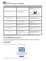
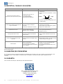
14 PROBLEMS, CAUSES AND CORRECTIVE ACTIONS
Table 14.1
Problems Causes Corrective Actions
There is circulation of reactive power
between alternators when operating in
parallel.
Phases sequence (R-S-T) incorrectly
connected;
CT connections are inverted;
Droop adjustment excessively low.
Connect phase sequence correctly.
Correctly polarize the CT in the phase shown
below:
Increase droop adjustment, rotating trimpot
P2 clockwise (CW).
Generated voltage decreases when load is
applied, and it doesn’t return.
Dropping speed of the driving machine;
Under frequency protection engaged.
Correct speed regulation.
Adjust Under frequency protection by rotating
trimpot P5 clockwise (CW).
Alternator voltage does not increase.
Residual voltage excessively low
Terminals F (+) and F (-) are inverted.
With the regulator switched- on, use external
battery (12Vcc) to force excitation (*).
Invert F (+) and F (-).
Generated voltage oscillates at no load.
Dynamic not well adjusted.
Alternator excitation voltage excessively
low.
Adjust trimpots P3 and P4;
Insert 10Ω/100W resistor in series with field.
Voltage oscillates at a specific load point.
Third harmonic of the auxiliary coil is
high.
Eliminate auxiliary coil and proceed with the
connections according to the diagrams of
page 13.
Voltage surges.
Lack of sensing.
Faulty electronic circuit.
Sensing voltage incompatible with
regulator.
Check if alternator phases are present in the
sensing.
If the regulator is encapsulated, replace it.
(*)For battery diesel generator where the alternator neutral is grounded battery should always be used independently.
15 PREVENTIVE MAINTENANCE
Periodical inspections of
the equipment are required to ensure they are clean, dust and moisture free. It is essential that
all terminal and connections are kept free from corrosion.
16 WARRANTY
See Installation and Maintenance Manual for WEG Alternators.
WEG Group - Energy Business Unit
Jaraguá do Sul - SC - Brazil
Telefono: 55 (47) 3276-4000
energia@weg.net
www.weg.net
P1
P2
S1
S2
Alternator
Load
A página está carregando...
A página está carregando...
A página está carregando...
A página está carregando...
A página está carregando...
A página está carregando...
A página está carregando...
A página está carregando...
A página está carregando...
A página está carregando...
A página está carregando...
A página está carregando...
A página está carregando...
A página está carregando...
A página está carregando...
A página está carregando...
A página está carregando...
A página está carregando...
A página está carregando...
A página está carregando...
A página está carregando...
A página está carregando...
A página está carregando...
A página está carregando...
A página está carregando...
A página está carregando...
A página está carregando...
A página está carregando...
A página está carregando...
A página está carregando...
A página está carregando...
-
 1
1
-
 2
2
-
 3
3
-
 4
4
-
 5
5
-
 6
6
-
 7
7
-
 8
8
-
 9
9
-
 10
10
-
 11
11
-
 12
12
-
 13
13
-
 14
14
-
 15
15
-
 16
16
-
 17
17
-
 18
18
-
 19
19
-
 20
20
-
 21
21
-
 22
22
-
 23
23
-
 24
24
-
 25
25
-
 26
26
-
 27
27
-
 28
28
-
 29
29
-
 30
30
-
 31
31
-
 32
32
-
 33
33
-
 34
34
-
 35
35
-
 36
36
-
 37
37
-
 38
38
-
 39
39
-
 40
40
-
 41
41
-
 42
42
-
 43
43
-
 44
44
-
 45
45
-
 46
46
-
 47
47
-
 48
48
-
 49
49
-
 50
50
-
 51
51


WEG AVR-A-OPT-04E Manual do usuário
- Tipo
- Manual do usuário
- Este manual também é adequado para
em outras línguas
- español: WEG AVR-A-OPT-04E Manual de usuario
- English: WEG AVR-A-OPT-04E User manual
Artigos relacionados
-
WEG AVR-A-OPT-07 Manual do usuário
-
-
-
-
-
-
-
-
-