

User Manual
EN
2

User Manual
EN
3
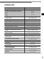
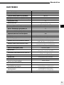
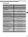
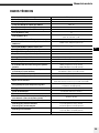
Tolerances and specifications conforming to IEC and CE standards.
Technical data is subject to change without notice.
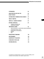
INTRODUCTION 2
ELB 1200 CARACTERISTICS 2
TECHNICAL DATA 3
USER SAFETY INFORMATION 4
CONTROL PANEL 6
DISPLAY PANEL – DASHBOARD 7
DEDICATED BUTTONS 8
• MODELLING LAMP
• USER SETTINGS
MENU FEATURES 11
• RADIO TRANSCEIVER FEATURES & SETUP
• FLASH MODE SETUP
• PHOTOCELL SETUP
• EXTRAS
• INFO
TROUBLESHOOTING 17
MAINTENANCE 18
STORAGE AND TRANSPORTATION 19
DISPOSAL AND RECYCLING 19
LEGAL INFORMATION 20

User Manual
EN
4
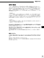
INTRODUCTION
INTRODUCTION
Dear photographer,
Thank you for buying the ELINCHROM ELB 1200 Unit. All Elinchrom products are
manufactured using the most advanced technology. Carefully selected components
are used to ensure the highest quality and the equipment is submitted to many tests
both during and after manufacture. We trust that it will give you many years of reliable
service.
Please read the instructions carefully before use, for your safety and to obtain maximum
benefit from many features.
Your Elinchrom-Team
Please read carefully the notes in this manual. This manual may show images of
products with accessories, which are not part of sets or single units. Elinchrom set and
single unit configurations may change without advice and may differ in other countries.
Please find actual configurations at www.elinchrom.com
For further details, upgrades, news and the latest information about the Elinchrom
System, please regularly visit the Elinchrom website. The latest user guides and
technical specifications can be downloaded in the “Support” area.
Technical data, features and functions of Elinchrom flash units, accessories and the
EL-Skyport system may change without advice. The listed values can differ due to
tolerances in components, or measuring instruments. Technical data, is subject to
change. No guarantee for misprints.
Please keep this user manual for later information and reference.
ELB1200 CARACTERISTICS
2x Outlets A + B with 2:1 (66%:33%) asymmetry and 1:1 (50%:50%) options. LED
illuminated outlets, show which head is active. Each connected head can be activated
or deactivated separately using the A and B buttons. Head recognition, shows if a Pro,
Hi-Sync, Action head is connected. Automatically displays the flash duration of each
(Pro / Action) head at all power levels. Elinchrom Creative Suite with strobo, delayed and
sequence features. USB for firmware updates.
Two versions of the ELB1200 Battery Pack are available:
• ELB1200 Li-Ion Battery HD 144 Wh (19296)
• ELB1200 Li-Ion Battery Air 90 Wh (19273)
The number of flashes may vary from battery to battery (due to ageing, storage
conditions etc.). Used Batteries may need to be recycled. Check your local regulations!

User Manual
EN
5
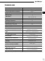
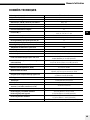
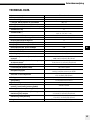
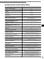
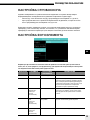
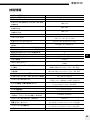
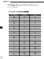
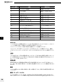
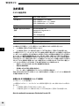
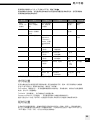
TECHNICAL DATA
Product Name and article number
ELB 1200 (10289.1)
Flash capacity (Ws/J)
1200
Power distribution
Asymmetrical 2:1 or symmetrical
F-Stop (1m, 100 ISO, reflector 48°) ELB 1200 Pro
100%: 128
F-Stop (1m, 100 ISO, reflector 48°) ELB 1200 Action
100%: 90.6
F-Stop (1m, 100 ISO, reflector 48°) ELB 1200 Hi-Sync
100%: 128
Power range F-stop
8.5
Power range Ws / J
100%: 14 – 1200 / 50%: 7 - 600
66%: 14 – 791 / 33%: 7 - 396
Power increments in F-Stop
Dial: 1/10 – left/right buttons 1 F-Stop
Best flash duration t0.5 max. power ELB 1200 Action
1/8850 s at 33%, power setting 4.7
Recycling FAST to full power, in s
1.7
Recycling DEFAULT, to full power in s
3
Recycling ECO to full power, in s
6
Color temperature in K° at max. power
5500
Auto Power Dumping
Adjusts power settings automatically
Power stability
+/- 0.03 %
Modelling lamp modes
On, free, prop, timer 1-60 s, VFC, dimmer 5-100%
Flashes out of one charged battery at min / max. power
20000 / 215 (Li-Ion Battery Air, included)
36000 / 400 (Li-Ion Battery HD, optional)
LED run time 1 / 2 heads (set flash power to minimum
value)
Up to 80 / 40 min. (Li-Ion Battery Air, included)
Up to 120 / 60 min. (Li-Ion Battery HD, optional)
Li-Ion Battery Air (included, 19273)
36V / 2.5 Ah / 90 Wh
Li-Ion Battery HD (optional, 19296)
36V / 4.0 Ah / 144 Wh
Battery Box options
USB charge socket for mobile devices: 5V max. 1 Amp., shipping mode
setting, battery charge status with 4 LED’s
Quick Charger: approx. recharge time in h
1.5 (Li-Ion Battery Air, included)
2.5 (Li-Ion Battery HD, optional)
EL-Skyport
Built-in, 20 frequency channels, 4 groups
Sync voltage
5V compatible with all cameras
Sync socket
3.5 mm jack
Dimensions in cm, complete unit including handle &
battery box / without battery box (WxDxH)
18x13x28 / 18x13x22
Dimensions in cm Battery Box (WxDxH)
18x13x7.5
Weight in kg (lbs), without Battery Box
Weight in kg (lbs), complete unit
3.2 (6.8 lbs) (Li-Ion Battery Air, included)
4.3 (9.48 lbs) (Li-Ion Battery HD, optional)
Weight in kg, Battery Box
1.1 (2.4 lbs) (Li-Ion Battery Air, included)
1.5 (3.3 lbs) (Li-Ion Battery HD, optional)
Supplied with
ELB1200, battery box, quick charger, sync cable

User Manual
EN
6
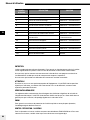
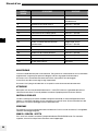
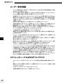
USER SAFETY INFORMATION
• Flash units are powerful light sources. Please be aware of the danger, or
inconvenience, that they may present to some persons and children.
• Keep flash units out of reach of unauthorised persons whenever possible.
• Keep flash units away from children!
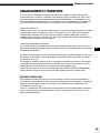
• According to safety regulations, we draw your attention to the fact that these
electronic flash units are not designed for outdoor use in excessively damp
or dusty conditions and should not be used after being exposed to sudden
temperature changes causing condensation. The humidity protection conforms to
the norms of IP20.
• Do not use without permission in restricted areas (such as hospitals, laboratories
etc.).
• Do not use near flammable / explosive material. Keep minimum 1m or more
distance to any object. Keep a general distance from other operating units.
• Never flash into the eyes of a subject without warning. Close use, may affect
eyesight.
• The ambient temperature whilst the unit is in use: min. -10°C (14°F) up to max.
40°C (104°F)
• There is high voltage and there can be high currents, so please apply all the usual
safety precautions when handling the unit.
• Flash systems store electrical energy in capacitors by applying high voltage,
please take care of open contacts and terminals.
• These units may retain an internal charge for a considerable time even though
disconnected. If it has been found to be faulty, please stop using it and return it for
repair.
• For your safety, never open or disassemble your flashes. Only an authorised
service engineer should open or attempt to repair this unit.
• Always switch off the flash unit before changing accessories.
• The unit, the flashtube and accessories may become very hot during and after
use! To avoid injury, handle with an insulating cloth or wait until parts have cooled
down. Avoid direct sunlight, which might heat up the flash unit and affect the
photocell efficiency. Protect the flash unit when used in humid conditions, but
ensure ventilation for cooling! On no account should any object be inserted into the
ventilation holes.
• Use only original Elinchrom Accessories. Damaged cables, glass domes and cases
must be immediately replaced by customer service.
FLASH TUBES AND LED-MODELLING LIGHT
• Flashtubes and the LED-Reflector dishes may become very hot during and after
use!
• Never touch a flash tube or exchange it before the unit has cooled down and is
disconnected from the power.
• Do not fire flashes from short distances directed towards a person.
• Do not use near flammable / explosive material.

User Manual
EN
7
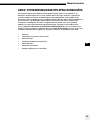
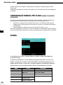
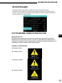
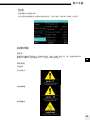
WARNING: PHOTOSENSITIVITY/EPILEPSY/SEIZURES
A very small percentage of individuals may experience epileptic seizures or blackouts
when exposed to certain light patterns or flashing lights. Exposure to certain patterns
or stroboscopic effects may trigger epileptic seizures or blackouts in these individuals.
These conditions may trigger previously undetected epileptic symptoms or seizures
in persons who have no history of prior seizures or epilepsy. If you, or anyone in your
family, has an epileptic condition or has had seizures of any kind, consult your physician
before using the EL unit. IMMEDIATELY DISCONTINUE use and consult your physician
before resuming use of your EL unit if you or your child experience any of the following
health problems or symptoms:
• Dizziness
• Eye or muscle twitches
• Disorientation
• Any involuntary movement
• Altered vision
• Loss of awareness
• Seizures or convulsion

User Manual
EN
8
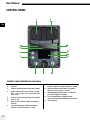
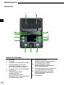
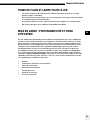
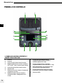
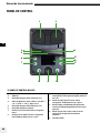
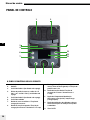
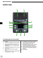
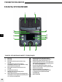
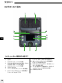
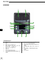
CONTROL PANEL
CONTROL PANEL FEATURES THE FOLLOWING
1. Outlet A
2. Outlet B
3. Outlet A on/off (located under the handle)
4. Power ratio between the outlets A and B
(66% : 33% or 50% : 50%), located under
the handle
5. Outlet B on/off (located under the handle)
6. Unit On /Off
7. Menu Access Button / Menu navigation
function
8. Left function button / Menu navigation
function / Power down by 1 F-stop
9. Scroll button (Menu navigation function ) /
Flash test (push) / power variation in 1/10th
10. Right function button / Menu navigation
function / Power up by 1 F-stop
11. LED Modelling Lamp Button : short push
(on/off) / long push (settings)
12. User setting button, toggle between
advanced and reduced display information
13. OLED Display
9 10
2
3
6
7
4
1
8
5
12
13
11

User Manual
EN
9
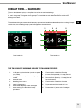
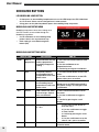
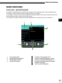
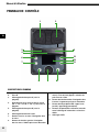
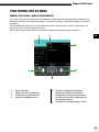
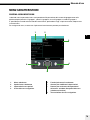
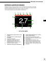
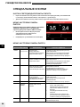
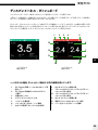
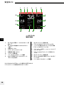
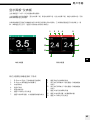
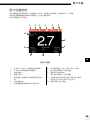
1. EL-Skyport synchronisation (normal or speed
sync mode)
2. EL-Skyport frequency channel and group
number
3. Photocell status
4. Modelling Lamp status
5. Battery charge status
6. Power outlet B / power ratio / head type
7. Power setting of the B outlet in f-stop
equivalents
8. Flash Duration value of the B outlet
9. Increase flash power by 1 f-stop (Effect of
function buttons)
10. Decrease flash power by 1 f-stop (Effect of
function buttons)
11. Flash Duration value of the A outlet
12. Power setting of the A outlet in f-stop
equivalents
13. Power outlet A / power ratio / head type
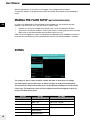
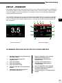
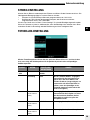
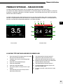
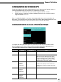
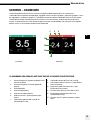
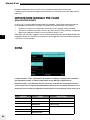
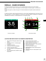
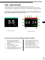
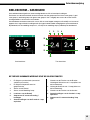
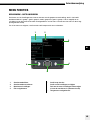
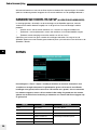
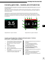
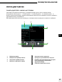
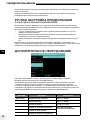
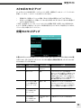
DISPLAY PANEL – DASHBOARD
The main dashboard displays a simplified view of one or two head settings.
The colours of the upper bar correspond to the group number : blue for the group 1, yellow for the group
2, red for the group 3 and green for the group 4. It is possible to switch between black or white menu
background colour.
The dashboard changes automatically between one and two heads view depending on the number of heads
switched on. Settings that are enabled are displayed on the dashboard. For example, if the modelling lamp is
switched on, the modelling lamp symbol will appear on the dashboard.
THE TWO HEAD VIEW DASHBOARD INCLUDE THE FOLLOWING FEATURES
1 2 3 4 5
6
7
811
12
13
910
One head view Two head view

User Manual
EN
10
DEDICATED BUTTONS
LED MODELLING LAMP BUTTON
• A short press on the modelling lamp button turns on the LED lamp of the ELB 1200 Head
for 15 seconds. Values can be changed from 1 to 60 seconds.
• A long press on the pilot lamp button opens the modelling lamp setup menu.
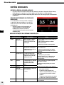
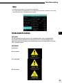
MODELLING LAMP SETUP MENU
Modelling lamp power value, timer settings and
the VFC function are accessible through the
Modelling Lamp Menu.
• Use A & B buttons to set modelling lamp
power values in the asymmetrical way.
• Ratio setting is accessible through the
button (A:B)
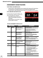
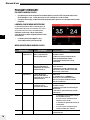
MODELLING LAMP SETTINGS MENU
MENU OPTIONS EXPLANATION HOW TO
Mode Free or
proportional
Switch between the free
and the proportional
modelling lamp power
setting
1. Press the Left Function button to enter
the menu.
2. Use the scroll button to set
proportional or free.
3. Confirm by pressing the scroll button.
Free The power value of
the modelling lamp is
independent of the flash
power value
1. Use Left Function button to leave the
menu
2. Use the scroll button to set the LED
power value, press to confirm.
Proportional The power value of
the modelling lamp is
proportional to the flash
power value
Fixed value.
Mode passes to FREE automatically if
the power settings are changed via the
scroll button.
VCF On/Off LED switches off, when
unit recharges. Optical
flash confirmation.
1. Press Left Function button to enter
the menu
2. Use the scroll button to toggle to
VFC.
3. Confirm by pressing the scroll
button.
Timer On/Off
• 1. Press Left Function button to
enter the menu
• 2. Use the scroll button to toggle
to Timer On/Off.
• 3. Confirm by pressing the scroll
button.
• 4. Use the scroll button to set the
value 5 – 60 s, press to confirm.
Timer value Modelling lamp timer,
5 – 60 s
exit To exit this menu, press the Right
Function button

User Manual
EN
11
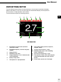
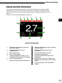
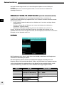
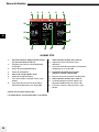
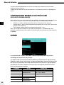
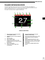
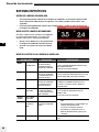
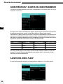
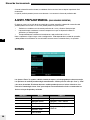
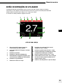
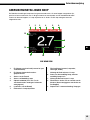
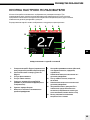
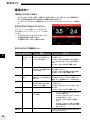
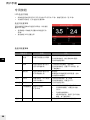
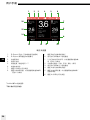
USER SETTINGS BUTTON
The User Settings button displays the advanced menu. If two heads are attached, the display
adapts automatically. In this case, the central part of the dashboard displays the total power of
the two heads, in f-stop equivalents and in Joules.
The one head view displays the following features:
1 2 3 4 5 6
7
8
91011
12
13
ONE HEAD VIEW
1. EL-Skyport synchronisation (normal or
speed sync mode)
2. EL-Skyport frequency channel and group
number
3. Photocell status
4. Modelling Lamp status
5. Charge speed (fast / eco / in default mode
no info displayed)
6. Battery charge status
7. Flash power in f-stop equivalents
8. Flash mode settings (normal, sequence,
delayed, strobo)
9. Increase flash power by 1 f-stop
10. Modelling lamp status, when modelling
lamp is switched on
11. Decrease flash power by 1 f-stop
12. Flash power in Joules / Ws & flash duration
value (only displayed with Action and Pro
Heads)
13. Power outlet / power ratio / head type

User Manual
EN
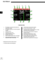
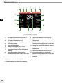
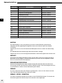
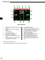
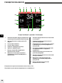
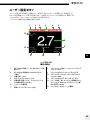
12
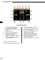
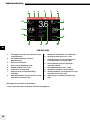
1. EL-Skyport synchronisation (normal or
speed sync mode)
2. EL-Skyport frequency channel and group
number
3. Photocell status
4. Modelling Lamp status
5. Charge speed (fast / eco)**
6. Battery charge status
7. Power outlet B / power ratio / head type
8. Power setting of the B outlet in f-stop
equivalents and in Joules (Ws)
9. Flash Duration value of the B outlet*
10. Increase flash power by 1 f-stop
11. Total flash power of the two heads, in f-stop
equivalents and in Joules (Ws)
12. Flash mode settings (normal, sequence,
delayed, strobo)
13. Decrease flash power by 1 f-stop
14. Flash duration value of the A outlet*
15. Power setting of the A outlet in f-stop
equivalents and in Joules / Ws
16. Power outlet A / power ratio / head type
531 642
16
15
14
1213 1011
7
8
9
TWO HEAD VIEW
*Displayed with Action and Pro heads
** In default mode no info displayed

User Manual
EN
13
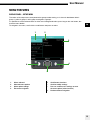
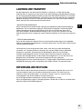
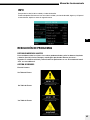
1
3
21
2
6
5
4
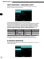
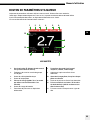
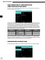
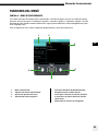
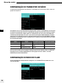
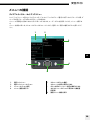
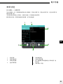
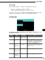
1. Menu selected
2. Selected menu options
3. Menu option settings
4. Exit menu navigation
5. Scroll button functions:
• Scroll to modify settings
• Press to confirm menu settings or enter
the menu option (select function)
6. Backward menu navigation
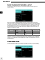
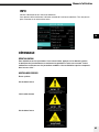
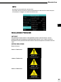
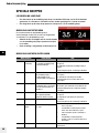
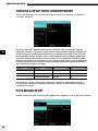
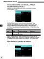
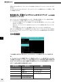
MENU FEATURES
DISPLAY PANEL – SETUP MENU
The colors of the setup menu correspond to the group number setting, as in the main dashboard: blue is
group 1, yellow is group 2, red is group 3 and green is group 4.
It is possible to switch between black or white menu background colour, press long on the user button, but
leave the menu before.
To navigate in the menu, scroll with the scroll button and press to select.

User Manual
EN
14
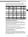
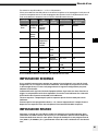
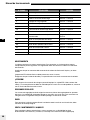
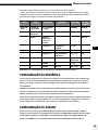
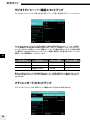
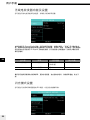
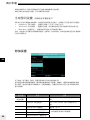
When you work with the EL-Skyport Radio system you can choose the synchronization
speed. The “normal” synchronization mode is good when long distances are needed whereas
the “speed” synchronisation can be used when higher shutter sync speeds are needed, with
enabled medium format cameras. Any change in these settings must be applied also to the
EL-Skyport Radio Transmitter to enable communication between the devices! Normal sync
mode is the standard sync mode.
Finally you can choose in which group and frequency you would like to work. Change group
settings to have independent control multiple groups of lights. Change frequency channel to
avoid interference.
DISPLAY OPTION OPTION SETTINGS DEFAULT SETTING
Radio Mode Normal / Speed Normal
Group 1 to 4 1
Frequency (channel) 1 to 20 1
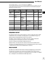
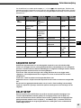
FLASH MODE SETUP
The flash mode menu enables you to configure your ELB unit to suit your style of shooting.
RADIO TRANSCEIVER FEATURES & SETUP
The Radio options allow you to select the synchronisation speed and to define group and
frequency settings.

User Manual
EN
15
To set the delay step to x 1, x 10 or x 100 steps press the button
The flash before ready feature gives you the choice between flashing the unit before full recycle
or to be able to flash only when the unit has fully recycled. You can also define recycling time
depending on the battery level left.
DISPLAY OPTION SUB- OPTION SUB-OPTION SETTINGS DEFAULT
SETTING
Flash
mode
Recycling time Eco / default
/ fast
Yes/no Default
Flash before
ready
Yes/no
Mode Normal /
Sequence
/ Delayed /
Strobo
Normal
Sequence Unit address 1 - 20 1
Sequence Total units 1 to 20 1
Sequence Sequence timeout 0.1’’-5.0’’ 2.0’’
Delayed Delay Steps: x1,
x10, x100
100 ms
Strobo Hz 1 - 20 1
Strobo Duration 0.5 – 5.0 s 2.0 s
Stay on default if you wish to do normal flash photography.
SEQUENCE SETUP
Use sequence mode to catch a moving sequence in a series of single frames with a number
of indexed flash units, for example, of a jumping person in up to 20 different images. The
following setup must be programmed in order to use the features.
Unit address : Every unit requires its own address; every time a trigger is released the
corresponding flash unit will respond. Up to 20 units can be addressed.
Total units : Indicates the total number of addressed flash units.
Sequence timeout : Time after which the sequence restarts back to first addressed unit.
The timeout can be programmed from 0.1s to 5s. This setting is the wait time after a sequence
is stopped, before it will restart from the beginning of the sequence.
DELAY SETUP
Set a delay for your ELB unit to flash with the set delay after triggering (e.g. second curtain).
The delay refers to the time (in ms) in which the unit should fire a flash after the camera
shutter has been opened. The delay time can be programmed from 1ms (0.001 s.) to 10000ms
(10 s.), enabling flash to be combined with ambient light sources.

User Manual
EN
16
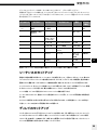
To fine-tune the milliseconds, the scale can be modified in 1, 10, and 100 steps. Press the
press the right function button to choose your step. This option is only active in the flash delay
setup menu.
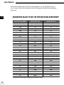
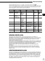
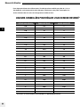
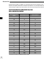
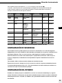
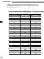
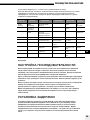
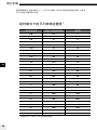
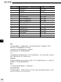
SUGGESTED VALUE TO SET ON THE ELB IN DELAYED MODE*
SYNC SPEED ON CAMERA EQUIVALENT IN MS SUGGESTED VALUE
1/60 16.6 9
1/50 20 12
1/40 25 17
1/30 33.3 23
1/25 40 30
1/20 50 40
1/15 66.6 52
1/13 77 68
1/10 100 90
1/8 125 115
1/6 166.6 145
1/5 200 185
1/4 250 235
0.3" 300 290
0.4" 400 370
0.5" 500 470
0.6" 600 580
0.8" 800 750
1" 1000 950
1.3" 1300 1200
1.6" 1600 1500
2" 2000 1900
2.5" 2500 2400
3.2" 3200 2900
4" 4000 3800
5" 5000 4800
6" 6000 5800
8" 8000 7700
10" 10000 9700
* tested with canon EOS 5D. Suggested for fullframe camera.

User Manual
EN
17
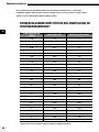
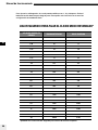
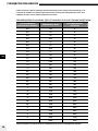
SUGGESTED VALUE TO SET ON THE ELB IN DELAYED MODE*
SYNC SPEED ON CAMERA EQUIVALENT IN MS SUGGESTED VALUE
1/60 16.6 9
1/50 20 12
1/40 25 17
1/30 33.3 23
1/25 40 30
1/20 50 40
1/15 66.6 52
1/13 77 68
1/10 100 90
1/8 125 115
1/6 166.6 145
1/5 200 185
1/4 250 235
0.3" 300 290
0.4" 400 370
0.5" 500 470
0.6" 600 580
0.8" 800 750
1" 1000 950
1.3" 1300 1200
1.6" 1600 1500
2" 2000 1900
2.5" 2500 2400
3.2" 3200 2900
4" 4000 3800
5" 5000 4800
6" 6000 5800
8" 8000 7700
10" 10000 9700
* tested with canon EOS 5D. Suggested for fullframe camera.
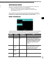
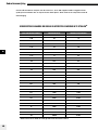
STROBO SETUP
Take an image with stroboscopic effects and open camera shutter. The overlapping moving
sequence is visible in one frame.
• Frequency Hz: Number of flashes per second. Programmable from 1 to 20Hz.
• Duration window: Time during of the moving sequence you wish to capture. Programmable
from 0.5 s. to 5 s.
Note: The unit must be set in fast recycling time in the “power settings” menu. If the error sound
is heard, this means the recycling time cannot keep up. Please reduce the Hz setting or the flash
power to a lower value.
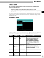
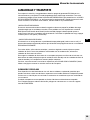
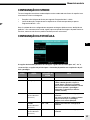
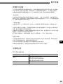
The photocell options allow you to set up the optical flash trigger to off, on and if required, the
pre-flash options for the perfect synchronisation with speedlight preflash sequences.
PHOTOCELL SETUP
DISPLAY OPTION OPTION SETTINGS NOTE
Photocell Mode Off / On / Preflash
Setup Auto Only accessible in « preflash mode »
Use the scroll button, go to Auto
mode and select this (suggested to
automatically count the number of
flashes when the speedlight is fired
at the photocell, and set the correct
number.)
Preflash cnt
(only experienced
users)
Manual / 1-20 Only accessible in « manual setup »
Use this option only if you know the
number of pre-flashes the speedlight
fires, plus the main flash.
Time frame
(only experienced
users)
0.5 ‘’-5.0’’ Only accessible in « manual setup »
Block time
(only experienced
users)
0.5 ms – 5.0 ms Only accessible in « manual setup »

User Manual
EN
18
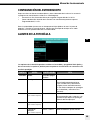
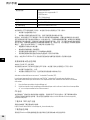
DISPLAY OPTION SETTINGS
Extras Auto std-by off / 1 min – 60 min
Auto - off off / 1 min – 60 min
Ready tone Tone 1 to 12
Ready volume Off/min/low/default/high/max
Error volume
Keyboard click
When the photocell is on, the flash unit will trigger at any recognised flash impulse.
The pre-flash option can be adjusted manually if the number of pre-flashes of the speedlight is
known.
MANUAL PRE-FLASH SETUP (ONLY EXPERIENCED USERS)
In some cases depending on the technology of the speedlite unit, the automatic pre-flash
detection may not work. In this case you can try a manual setup.
• Preflash cnt : set up the number of pre-flashes from 1 to 20 and add the main flash.
• Time frame : set the time window in which all pre-flashes, including the main flash, are fired
• Block time: set the delay between each pre-flash from 0.5 to 5 ms.
Note: we cannot suggest any values or setting here; this depends on the speedlite unit and must
be tested until the correct synchronisation between the flash unit and the speedlite is achieved.
The settings in “Extras” help you define standby and when to auto-off to save energy.
The audio options give you the choice of different settings for ready, error and keytones.
The volume of the ready, error and key tones can be adjusted, enabling you to work silently
if necessary. The ready tone can be chosen to improve acoustical recognition of when all
flashes have fired and recycled.
EXTRAS

User Manual
EN
19
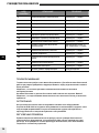
See Error Table
TROUBLESHOOTING
SOFT RESET
To reset all settings to default values, push the left and right ( function ) buttons at the same
time and hold for at least 1 second. The unit will reboot and will clear all working parameters.
This will not reset the counter in the “Info” menu.
ERROR MANAGEMENT
System Error
See Error Table
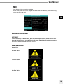
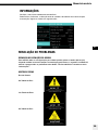
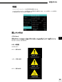
INFO
Check lifetime of the unit and the flashtube.
You can easily check the current usage of the unit and the flashtube. Very useful for servicing,
rental or second-hand retail.
See Error Table

User Manual
EN
20
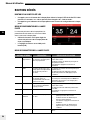
ERROR NUMBER DESRIPTION SOLUTION
-1 Capacitors over voltage Restart -> Service
-2 System overheat Wait until cooling down
-3 Discharge circuit fault Restart -> Service
-4 Charge Timeout Restart -> Service
-9 No input voltage on SMPS ! Restart -> Service
-15 Charge MOS thermistor open Restart -> Service
-18 Discharge MOS thermistor open Restart -> Service
-19 capacitor thermistor open Restart -> Service
-24 Capacitor voltage symmetry error OFF 10 min. Restart ->
Service
-26 Booster voltage error Restart -> Service
-28 Tube hanged Restart -> Service
-60 System peripheral bus error Restart -> Service
-62 System memory error Restart -> Service
-99 Uncategorized error Restart -> Service
-101 low battery level Warning
MAINTENANCE
The head requires only very little maintenance. To ensure secure operation please check the
following points regularly before connecting the head to the power pack:
Ensure that the contacts of the flashhead connector are clean and undamaged.
The flash cable should not have any marks or cuts. Important!!
Ensure that the plug-in flash tube and the glass dome are correctly fitted.
CAUTION!
Under no circumstances open any part of the equipment. The ELB 1200 unit is not user
serviceable and contains high voltage. In the event of difficulties contact your Elinchrom Service
partner.
REGULAR CHECK
National safety regulations require frequent safety checks of the electrical equipment. The ELB
1200 unit should be checked once a year. This check not only guarantees safety; it also protects
the value of the unit.
SHIPPING
To achieve maximum protection of the unit when sending it in for service, the original packaging
should be kept.
SALES / SERVICE / RENTAL
For service and sales, please contact your local ELINCHROM Distributor. For contact and
support, please visit http://www.elinchrom.com/support.php
A página está carregando...
A página está carregando...
A página está carregando...
A página está carregando...
A página está carregando...
A página está carregando...
A página está carregando...
A página está carregando...
A página está carregando...
A página está carregando...
A página está carregando...
A página está carregando...
A página está carregando...
A página está carregando...
A página está carregando...
A página está carregando...
A página está carregando...
A página está carregando...
A página está carregando...
A página está carregando...
A página está carregando...
A página está carregando...
A página está carregando...
A página está carregando...
A página está carregando...
A página está carregando...
A página está carregando...
A página está carregando...
A página está carregando...
A página está carregando...
A página está carregando...
A página está carregando...
A página está carregando...
A página está carregando...
A página está carregando...
A página está carregando...
A página está carregando...
A página está carregando...
A página está carregando...
A página está carregando...
A página está carregando...
A página está carregando...
A página está carregando...
A página está carregando...
A página está carregando...
A página está carregando...
A página está carregando...
A página está carregando...
A página está carregando...
A página está carregando...
A página está carregando...
A página está carregando...
A página está carregando...
A página está carregando...
A página está carregando...
A página está carregando...
A página está carregando...
A página está carregando...
A página está carregando...
A página está carregando...
A página está carregando...
A página está carregando...
A página está carregando...
A página está carregando...
A página está carregando...
A página está carregando...
A página está carregando...
A página está carregando...
A página está carregando...
A página está carregando...
A página está carregando...
A página está carregando...
A página está carregando...
A página está carregando...
A página está carregando...
A página está carregando...
A página está carregando...
A página está carregando...
A página está carregando...
A página está carregando...
A página está carregando...
A página está carregando...
A página está carregando...
A página está carregando...
A página está carregando...
A página está carregando...
A página está carregando...
A página está carregando...
A página está carregando...
A página está carregando...
A página está carregando...
A página está carregando...
A página está carregando...
A página está carregando...
A página está carregando...
A página está carregando...
A página está carregando...
A página está carregando...
A página está carregando...
A página está carregando...
A página está carregando...
A página está carregando...
A página está carregando...
A página está carregando...
A página está carregando...
A página está carregando...
A página está carregando...
A página está carregando...
A página está carregando...
A página está carregando...
A página está carregando...
A página está carregando...
A página está carregando...
A página está carregando...
A página está carregando...
A página está carregando...
A página está carregando...
A página está carregando...
A página está carregando...
A página está carregando...
A página está carregando...
A página está carregando...
A página está carregando...
A página está carregando...
A página está carregando...
A página está carregando...
A página está carregando...
A página está carregando...
A página está carregando...
A página está carregando...
A página está carregando...
A página está carregando...
A página está carregando...
A página está carregando...
A página está carregando...
A página está carregando...
A página está carregando...
A página está carregando...
A página está carregando...
A página está carregando...
A página está carregando...
A página está carregando...
A página está carregando...
A página está carregando...
A página está carregando...
A página está carregando...
A página está carregando...
A página está carregando...
A página está carregando...
A página está carregando...
A página está carregando...
A página está carregando...
A página está carregando...
A página está carregando...
A página está carregando...
A página está carregando...
A página está carregando...
A página está carregando...
A página está carregando...
A página está carregando...
A página está carregando...
A página está carregando...
A página está carregando...
A página está carregando...
A página está carregando...
A página está carregando...
A página está carregando...
A página está carregando...
A página está carregando...
A página está carregando...
A página está carregando...
A página está carregando...
A página está carregando...
A página está carregando...
A página está carregando...
A página está carregando...
A página está carregando...
A página está carregando...
A página está carregando...
A página está carregando...
A página está carregando...
A página está carregando...
A página está carregando...
A página está carregando...
A página está carregando...
A página está carregando...
A página está carregando...
A página está carregando...
A página está carregando...
A página está carregando...
A página está carregando...
A página está carregando...
A página está carregando...
A página está carregando...
A página está carregando...
A página está carregando...
A página está carregando...
A página está carregando...
A página está carregando...
A página está carregando...
A página está carregando...
A página está carregando...
-
 1
1
-
 2
2
-
 3
3
-
 4
4
-
 5
5
-
 6
6
-
 7
7
-
 8
8
-
 9
9
-
 10
10
-
 11
11
-
 12
12
-
 13
13
-
 14
14
-
 15
15
-
 16
16
-
 17
17
-
 18
18
-
 19
19
-
 20
20
-
 21
21
-
 22
22
-
 23
23
-
 24
24
-
 25
25
-
 26
26
-
 27
27
-
 28
28
-
 29
29
-
 30
30
-
 31
31
-
 32
32
-
 33
33
-
 34
34
-
 35
35
-
 36
36
-
 37
37
-
 38
38
-
 39
39
-
 40
40
-
 41
41
-
 42
42
-
 43
43
-
 44
44
-
 45
45
-
 46
46
-
 47
47
-
 48
48
-
 49
49
-
 50
50
-
 51
51
-
 52
52
-
 53
53
-
 54
54
-
 55
55
-
 56
56
-
 57
57
-
 58
58
-
 59
59
-
 60
60
-
 61
61
-
 62
62
-
 63
63
-
 64
64
-
 65
65
-
 66
66
-
 67
67
-
 68
68
-
 69
69
-
 70
70
-
 71
71
-
 72
72
-
 73
73
-
 74
74
-
 75
75
-
 76
76
-
 77
77
-
 78
78
-
 79
79
-
 80
80
-
 81
81
-
 82
82
-
 83
83
-
 84
84
-
 85
85
-
 86
86
-
 87
87
-
 88
88
-
 89
89
-
 90
90
-
 91
91
-
 92
92
-
 93
93
-
 94
94
-
 95
95
-
 96
96
-
 97
97
-
 98
98
-
 99
99
-
 100
100
-
 101
101
-
 102
102
-
 103
103
-
 104
104
-
 105
105
-
 106
106
-
 107
107
-
 108
108
-
 109
109
-
 110
110
-
 111
111
-
 112
112
-
 113
113
-
 114
114
-
 115
115
-
 116
116
-
 117
117
-
 118
118
-
 119
119
-
 120
120
-
 121
121
-
 122
122
-
 123
123
-
 124
124
-
 125
125
-
 126
126
-
 127
127
-
 128
128
-
 129
129
-
 130
130
-
 131
131
-
 132
132
-
 133
133
-
 134
134
-
 135
135
-
 136
136
-
 137
137
-
 138
138
-
 139
139
-
 140
140
-
 141
141
-
 142
142
-
 143
143
-
 144
144
-
 145
145
-
 146
146
-
 147
147
-
 148
148
-
 149
149
-
 150
150
-
 151
151
-
 152
152
-
 153
153
-
 154
154
-
 155
155
-
 156
156
-
 157
157
-
 158
158
-
 159
159
-
 160
160
-
 161
161
-
 162
162
-
 163
163
-
 164
164
-
 165
165
-
 166
166
-
 167
167
-
 168
168
-
 169
169
-
 170
170
-
 171
171
-
 172
172
-
 173
173
-
 174
174
-
 175
175
-
 176
176
-
 177
177
-
 178
178
-
 179
179
-
 180
180
-
 181
181
-
 182
182
-
 183
183
-
 184
184
-
 185
185
-
 186
186
-
 187
187
-
 188
188
-
 189
189
-
 190
190
-
 191
191
-
 192
192
-
 193
193
-
 194
194
-
 195
195
-
 196
196
-
 197
197
-
 198
198
-
 199
199
-
 200
200
-
 201
201
-
 202
202
-
 203
203
-
 204
204
-
 205
205
-
 206
206
-
 207
207
-
 208
208
-
 209
209
-
 210
210
-
 211
211
-
 212
212
-
 213
213
-
 214
214
-
 215
215
-
 216
216
-
 217
217
-
 218
218
-
 219
219
-
 220
220
-
 221
221
-
 222
222


Elinchrom ELB 1200 - Unit Manual do usuário
- Tipo
- Manual do usuário
- Este manual também é adequado para
em outras línguas
- español: Elinchrom ELB 1200 - Unit Manual de usuario
- français: Elinchrom ELB 1200 - Unit Manuel utilisateur
- italiano: Elinchrom ELB 1200 - Unit Manuale utente
- English: Elinchrom ELB 1200 - Unit User manual
- русский: Elinchrom ELB 1200 - Unit Руководство пользователя
- Nederlands: Elinchrom ELB 1200 - Unit Handleiding
- Deutsch: Elinchrom ELB 1200 - Unit Benutzerhandbuch
- 日本語: Elinchrom ELB 1200 - Unit ユーザーマニュアル
Artigos relacionados
-
Elinchrom ELB 1200 - Charger Manual do usuário
-
-
-
-
-
-