Elinchrom ELB 500 TTL Unit Manual do usuário
- Tipo
- Manual do usuário

Elinchrom LTD – ELB 500 TTL Unit – 11.2020
ELB 500 TTL UNIT
EN
FR
ES
IT
NL
DE
PT
USER MANUAL
GEBRAUCHSANLEITUNG
MANUEL D’UTILISATION
MANUALE D’USO
MANUAL DE FUNCIONAMIENTO
MANUAL DO USUÁRIO
GEBRUIKSAANWIJZING
РУКОВОДСТВО ПО ЭКСПЛУАТАЦИИ
ユーザーマニュアル
用户手册


EN
3
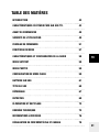
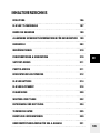
TABLE OF CONTENTS
INTRODUCTION 4
ELB 500 TTL CHARACTERISTICS 5
BEFORE YOU START 7
GENERAL USER SAFETY INFORMATION 7
CONTROL PANEL 12
MENU FEATURES 19
RADIO FEATURES & SETUP 19
SKYPORT MODE 20
PHOTTIX MODE 20
FLASH MODE SETUP 21
ELB 500 BATTERY 23
ELB 500 HEAD 27
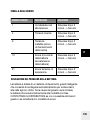
TROUBLESHOOTING 29
MAINTENANCE 31
DISPOSAL AND REYCLING 33
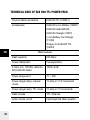
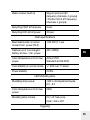
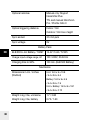
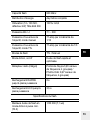
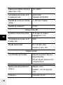
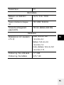
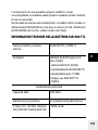
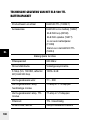
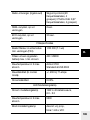
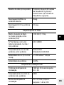
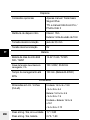
TECHNICAL DATA 34
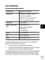
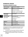
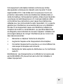
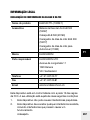
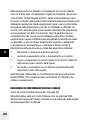
LEGAL INFORMATION 36
DECLARATION OF CONFORMITYUSA & CANADA 39

EN
4
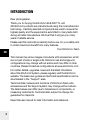
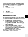
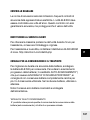
INTRODUCTION
Dear photographer,
Thank you for buying the Elinchrom ELB 500 TTL unit.
All Elinchrom products are manufactured using the most advanced
technology. Carefully selected components are used to ensure the
highest quality and the equipment is submitted to many tests both
during and after manufacture. We trust that it will give you many
years of reliable service.
Please read the instructions carefully before use, for your safety and
to obtain maximum benefit from many features.
Your Elinchrom-Team
This manual may show images of products with accessories, which
are not part of sets or single units. Elinchrom set and single unit
configurations may change without advice and may differ in other
countries. Please find actual configurations at www.elinchrom.com
For further details, upgrades, news and the latest information
about the Elinchrom System, please regularly visit the Elinchrom
website. The latest user guides and technical specifications can be
downloaded in the “Support” area.
Technical data, features and functions of Elinchrom flash units,
accessories and the Skyport system may change without advice.
The listed values can differ due to tolerances in components, or
measuring instruments. Technical data, subject to change. No
guarantee for misprints.
Keep this user manual for later information and reference.

EN
5
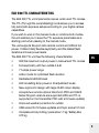
ELB 500 TTL CHARACTERISTICS
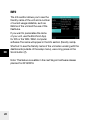
The ELB 500 TTL unit implements manual, action and TTL modes.
The TTL (Through the Lens Metering) mode allows you to access
fully automatic exposure setups according to your digital camera
capabilities.
If you wish to work in the manual mode or combine both modes,
the unit enables you to save the TTL exposure parameters as a
starting point when passing to the manual mode.
The unit supports Skyport radio remote control and HSS at full
power. It offers totally flexible asymmetry and the fastest flash
durations at lower power levels.
The ELB 500 TTL unit has the following characteristics:
• 500 Ws maximum output power in manual and TTL modes
• Full asymmetry with two outlets A & B
• 7 f-stops power range
• Action mode for optimised flash duration
• Dedicated ELB 500 Head
• LED modelling lamp power in 40 adjustment levels
• New ergonomic design with large OLED colour display
• Accepts two remote options: Elinchrom PRO and Odin2.
Earlier Skyport versions are supported (HSS and TTL is
supported on the Transmitter PRO with a firmware update)
• Improved weather protection for outlets
• USB socket for firmware updates and Sync socket 3.5 mm
• Complete unit only 2.49 kg / pack alone 1.7 kg / Battery Box
0.73 kg

EN
6
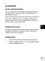
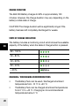
ELINCHROM TTL MODE CHARACTERISTICS
• 7 f-stop flash power range
• TTL +/- 3 f-stops adjustable in 1/3 steps.
• LED modelling lamp is adjustable in 40 power steps
• Compatible with Canon and Nikon. Other camera brands
will follow.
• Also compatible with Phottix Odin2 radio triggers for Canon,
Nikon and Sony
MANUAL MODE CHARACTERISTICS
• Full asymmetry
• Compatible wi
th all Skyport Transmitters
• Flash power in 1/10 f-stop steps
• Action Mode, fast flash durations at all power levels
• Saves the TTL power as a starting point for the manual mode
ELB 500 LI-ION BATTERY FEATURES
• Lightweight Li-Ion battery technology, only 0.73 kg
• Approx. 400 flashes at full power.
• Battery charging time 100 min. to 90%
• Easy battery locking system
• Compatible with ELB 400 charger (19279)

EN
7
ELB 500 HEAD FEATURES
• Ultra-compact design with flexible 2.5 m cable
• Universal use: single head for Hi-Sync and normal mode
• Dedicated flash tube for the ELB 500 head
• LED modelling lamp 14W (40 steps), 5200K, 90 CRI
• 7 mm umbrella shaft
• Q mount for Quadra accessories
• Optional Quadra Reflector Adapter MK-II (26342) to adapt to
EL - accessories
BEFORE YOU START
GENERAL USER SAFETY INFORMATION
• Flash units are powerful light sources. Please be aware of
the danger, or inconvenience, that they may present to some
persons and children.
• Keep flash units out of reach of unauthorised persons
whenever possible.
• Keep flash units away from children!
• According to safety regulations, we draw your attention
to the fact that electronic flash units are not designed
for extreme outdoor use, in damp or dusty conditions
and should not be used after being exposed to sudden
temperature changes causing condensation. The humidity
protection conforms to the norms of IP20.
• Do not use without permission in restricted areas (such as
hospitals, laboratories etc.).
• Do not use near flammable / explosive material. Keep
minimum 1m or more distance to any object.

EN
8
• Never flash into the eyes of a subject without warning. Close
use, may affect eyesight.
• The ambient temperature whilst the unit is in use: min. -20°C
(-4°F) up to max. 35°C (95°F). Storage temperature: -10°C up
to 60°C, optimal charging temperature: 0°C up to 45°C.
• There is high voltage and there can be high currents, so
please apply all the usual safety precautions when handling
the unit.
• Do not connect the flash head to to the pack without a
mounted and working flashtube due to high voltage at the
exposed terminals!
• Flash systems store electrical energy in capacitors by
applying high voltage.
• The units may retain an internal charge for a considerable
time even though disconnected from the battery. Internal
defective charge capacitors may explode whilst the unit is in
use, so never switch on a flash unit, once it has been found
to be faulty.
• For your safety, never open or disassemble your flashes.
Only an authorized service engineer should open or attempt
to repair this unit.
• Always switch off the flash unit before changing accessories.
• The unit, the flashtube and accessories may become very
hot during and after use! To avoid injuries, handle with an
insulating cloth or wait until parts have cooled down. Avoid
direct sunlight, which might heat up the flash unit and affect
the photocell efficiency. Protect the flash unit when used in
humid conditions, but ensure ventilation for cooling!
• On no account should any object be inserted into the
ventilation holes.

EN
9
• Use only original Elinchrom Accessories. Damaged cables,
glass domes and cases must be immediately replaced by
customer service.
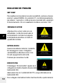
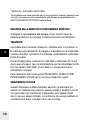
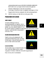
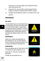
WARNING: PHOTOSENSITIVITY / EPILEPSY / SEIZURES
A very small percentage of individuals may experience epileptic
seizures or blackouts when exposed to certain light patterns or
flashing lights. These conditions may trigger previously undetected
epileptic symptoms or seizures in persons who have no history of
prior seizures or epilepsy. If you, or anyone in your family, has an
epileptic condition or has had seizures of any kind, consult your
physician before using the EL unit.
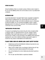
IMMEDIATELY DISCONTINUE use and consult your physician
before resuming use of your EL unit if you or any person
experiences any of the following health problems or symptoms:
• Dizziness
• Eye or muscle twitches
• Disorientation
• Any involuntary movement
• Altered vision
• Loss of awareness
• Seizures or convulsion
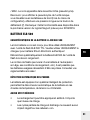
BATTERY SAFETY NOTICE
IMPORTANT! FOR YOUR SAFETY do not use the Battery Pack
for a purpose other than those specified, USE WITH ELINCHROM
EQUIPMENT ONLY!

EN
10
• To recharge the Battery Pack, use ONLY the Elinchrom
Li-Ion Battery Charger. If the recharging operation fails
to complete even when a specified recharging time has
elapsed, immediately stop further recharging and disconnect
the charger.
• If the Battery Pack gives off odours, generates heat,
becomes discoloured or deformed, or in any way appears
abnormal during use, recharging or storage, immediately
remove it from the equipment or Battery Charger and stop
using it.
DO NOT USE A FAULTY, APPARENTLY DAMAGED OR
DEFORMED BATTERY PACK!
ELECTRICAL, CHEMICAL AND MECHANICAL HAZARDS
• Do not disassemble, open or modify the Battery Pack.
• Do not connect the positive (+) and negative (-) terminals with
a metal object such as wire. Do not transport or store the
Battery Pack together with metal objects such as necklaces,
hairpins, etc.
• Do not pierce the Battery Pack with a nail or other sharp
objects, strike it with a hammer, or stand on it.
• Do not strike or throw the Battery Pack.
• If the Battery Pack leaks and electrolyte gets into the eyes,
do not rub them. Instead, rinse the eyes with clean running
water and immediately seek medical attention. Otherwise,
eye injury may result.

EN
11
OTHER HAZARDS
Store the Battery Pack in a location where children cannot reach it.
Do not put the Battery Pack into a microwave oven or a pressurized
container.
OUTDOOR USE
CAUTION! PROTECT THE BATTERY PACK AGAINST HUMIDITY!
This product is designed for dry use and should not come into
contact with water or dust. In humid conditions cover or otherwise
protect the battery. Do not immerse the Battery Pack in water /
seawater and do not allow it to get wet. The humidity protection
conforms to the norms of IP20.
TEMPERATURE PRECAUTIONS
To prevent overheating the product should not be covered whilst
in charge mode or in general use! Do not use, charge or leave
the Battery Pack near a heat source (+60°C or higher) such as
anopen fire, a heater or direct sunlight. If the Battery Pack has been
exposed to very cold conditions, sudden exposure to warm or
humid air may cause condensation and malfunction.
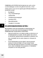
FLASH TUBES AND LED-MODELLING LIGHT SAFETY NOTICE
• Flashtubes and the LED-Reflector dishes may become very
hot during and after use!
• Never touch a flash tube or exchange it before the unit has
cooled down and is disconnected from the pack.
• Do not fire flashes from short distances directed towards a
person.
• Do not use near flammable / explosive material.

EN
12
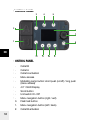
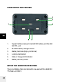
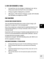
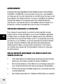
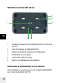
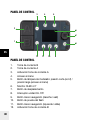
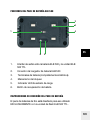
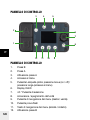
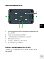
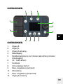
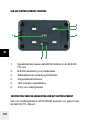
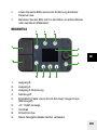
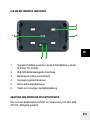
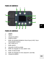
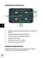
CONTROL PANEL
CONTROL PANEL
1. Outlet B
2. Outlet A
3. Outlet A activation
4. Menu access
5. Modelling Lamp button: short push (on/off) / long push
(menu access)
6. 4.3’’ OLED Display
7. Scroll button
8. Unit switch On /Off
9. Menu navigation button (right / exit)
10. Flash test button
11. Menu navigation button (left / back)
12. Outlet B activation
5
9101112
3
2
6
7
8
1
4

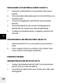
EN
13
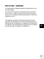
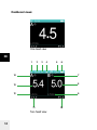
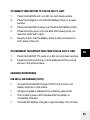
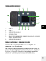
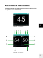
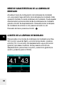
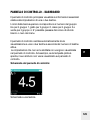
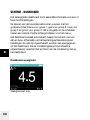
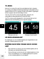
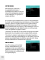
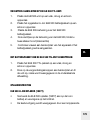
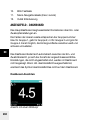
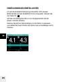
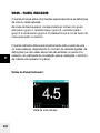
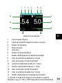
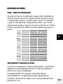
DISPLAY PANEL – DASHBOARD
The main dashboard displays essential information about one or
two head settings.
The colours of the upper bar correspond to the group number :
blue for group 1, yellow for group 2, red for group 3 and green
for group 4. It is possible to switch between black or white menu
background colour.
The dashboard changes automatically between the one and
two head view depending on the number of heads switched on.
Settings that are not enabled are not displayed in the dashboard.
For example, if the modelling lamp is switched off, the modelling
lamp symbol does not appear on the dashboard.

EN
14
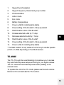
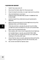
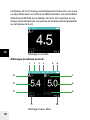
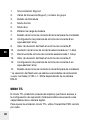
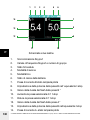
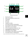
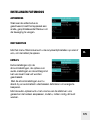
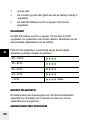
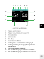
Dashboard views:
One head view
Two head view
714
13
12
11 10
654321
8
9

EN
15
1. Skyport Synchronisation
2. Skyport frequency channel and group number
3. Photocell status
4. Action mode
5. Eco mode
6. Battery charge status
7. Power outlet B modelling lamp status
8. Power setting of the B outlet in f-stop equivalent
9. Flash Duration value of the B outlet*
10. Increase selected outlet by 1 f-stop
11. Decrease selected outlet by 1 f-stop
12. Flash Duration value of the A outlet*
13. Power setting of the B outlet in f-stop equivalent
14. Power outlet A modelling lamp status
* The flash duration is only visible at normal x-sync shutter speeds
(1/125 or 1/250s depending on the DSLR camera.
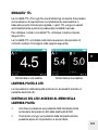
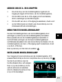
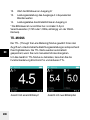
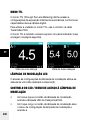
TTL MODE
The TTL (Through the Lens Metering) mode allows you to access
fully automatic exposure setups according to your digital camera.
The TTL values are automatically saved when passing to the
manual mode.
To operate the unit in the TTL mode, please use the radio remote
Elinchrom Pro and activate the TTL function.

EN
16
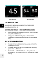
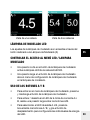
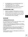
One head view Two head view
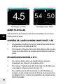
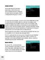
LED MODELLING LAMP
Modelling lamp settings are accessible through a dedicated
Modelling Lamp button (5).
CONTROLLING THE LED / MOD LAMP MENU ACCESS
• A short press on the modelling lamp button turns on the LED
lamp of the ELB 500 Head.
• A long press on the modelling lamp button opens the
modelling lamp setup menu and switches on the modelling
lamp.
USE OF THE A AND B BUTTONS
• To enter into the modelling lamp menu, press and hold the
modelling lamp button.
• To enable / disable the LED of the A or B outlet, use a long
press on the A / B buttons.
• To select the A or B outlet LED, use a short press on the A /
B buttons, and turn the scroll button for individual LED power
settings.

EN
17
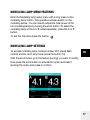
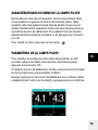
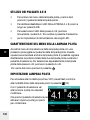
MODELLING LAMP MENU FEATURES
Enter the Modelling lamp setup menu with a long press on the
modelling lamp button. This operation will also switch on the
modelling lamps. You can directly adjust the total power of the
two modelling lamps by turning the scroll button. To select the
modelling lamp of the A or B outlet separately, press the A or B
button.
To exit the the menu press the button.
MODELLING LAMP SETTINGS
To access modelling lamp mode prop/free, VFC (visual flash
control) and the mod. lamp timer press the button (10).
With the scroll button go to the feature (turning) you want to modify.
Now press the scroll button to activate the option and select
(turning) the option and press to confirm.

EN
18
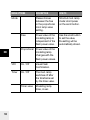
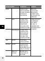
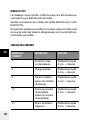
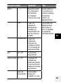
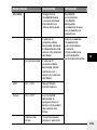
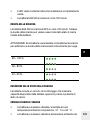
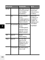
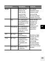
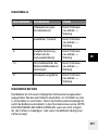
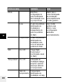
MENU OPTIONS DESCRIPTION HOW TO
Mode Please choose
between the free
or the proportional
mod. lamp value
setting.
Shortcut mod. lamp
mode: short press
on the scroll button.
Free Power value of the
modelling lamp is
independent of the
flash power value.
Use the scroll button
to set the value,
the setting will be
automatically stored.
Proportional Power value of the
modelling lamp
changes with the
flash power values.
VFC On / Off Visual Flash
Confirmation.
Timer On / Off The mod. lamp
switches off after
the timeframe set
by the timer value.
Timer value Modelling lamp
timer, in sec

EN
19
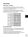
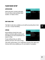
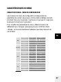
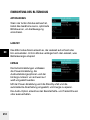
MENU FEATURES
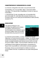
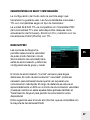
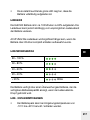
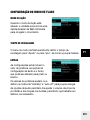
DISPLAY PANEL – SETUP MENU
The colors of the setup menu correspond to the group number
setting, as in the main dashboard: blue for group 1, yellow for group
2, red for group 3 and green for group 4.
To modify the menu settings, use the scroll button to navigate
and then press to confirm. In “Extras” the background of the user
interface can be switched from black to white.
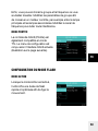
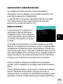
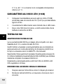
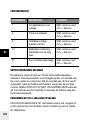
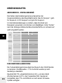
RADIO FEATURES & SETUP
The radio setup mode allows you to choose which transmitter you
would like to use. The manual / TTL functionalities are supported
according to the transmitter type.
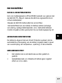
The ELB 500 TTL unit supports the Transmitter PRO (TTL
functionallity is only available after firmware update), Elinchrom Pro
as well as the Odin2 (Phottix) transmitters with TTL.
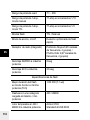
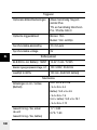
Radio
System Skyport Odin 2
Mode Off Normal Speed
Group 1-4
Frequency 1-20
Flash
mode
Action On Off
Photocell On Off
Recycling time Fast Eco
Extra
Auto stand-by Off 1-59 min.
Auto-off Off 1-60 min.
Ready tone On Off
Keyboard click On Off
Background Black White
Info
Friendly name Set through computer software.
Firmware rev. *******
Serial number *******
Life time In hours (hhhh:mm)
Flash count Total flash number

EN
20
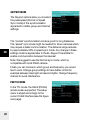
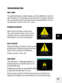
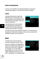
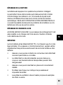
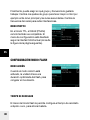
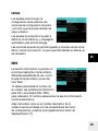
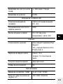
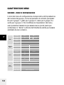
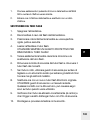
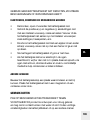
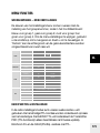
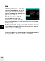
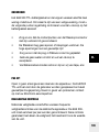
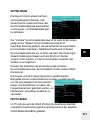
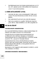
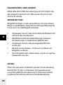
SKYPORT MODE
The Skyport options allow you to select
the pulse speed (Normal or Speed
Sync mode) of the synchronisation
signal and to define group and channel
settings.
The “normal” synchronization mode is good for long distances.
The “speed” sync mode might be needed for future cameras which
may require a faster communication. The distance range reduces
by approximately 50% in speed sync mode. Any change in these
settings must be applied also to the EL-Skyport Transmitter to
enable communication between the devices!
Note: We suggest to use the Normal sync mode, which is
compatible with most DSLR camera.
Finally you can choose in which group and frequency you would
like to work. Change group settings to have better control for
example between main light and second lights. Change frequency
channel to avoid interference.
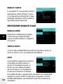
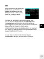
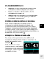
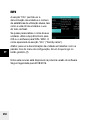
PHOTTIX MODE
In the TTL mode, the Odin2 (Phottix)
remote is also supported. The setup
menu is styled accordingly to the
current Odin2 interface (see the figure
next page).
A página está carregando...
A página está carregando...
A página está carregando...
A página está carregando...
A página está carregando...
A página está carregando...
A página está carregando...
A página está carregando...
A página está carregando...
A página está carregando...
A página está carregando...
A página está carregando...
A página está carregando...
A página está carregando...
A página está carregando...
A página está carregando...
A página está carregando...
A página está carregando...
A página está carregando...
A página está carregando...
A página está carregando...
A página está carregando...
A página está carregando...
A página está carregando...
A página está carregando...
A página está carregando...
A página está carregando...
A página está carregando...
A página está carregando...
A página está carregando...
A página está carregando...
A página está carregando...
A página está carregando...
A página está carregando...
A página está carregando...
A página está carregando...
A página está carregando...
A página está carregando...
A página está carregando...
A página está carregando...
A página está carregando...
A página está carregando...
A página está carregando...
A página está carregando...
A página está carregando...
A página está carregando...
A página está carregando...
A página está carregando...
A página está carregando...
A página está carregando...
A página está carregando...
A página está carregando...
A página está carregando...
A página está carregando...
A página está carregando...
A página está carregando...
A página está carregando...
A página está carregando...
A página está carregando...
A página está carregando...
A página está carregando...
A página está carregando...
A página está carregando...
A página está carregando...
A página está carregando...
A página está carregando...
A página está carregando...
A página está carregando...
A página está carregando...
A página está carregando...
A página está carregando...
A página está carregando...
A página está carregando...
A página está carregando...
A página está carregando...
A página está carregando...
A página está carregando...
A página está carregando...
A página está carregando...
A página está carregando...
A página está carregando...
A página está carregando...
A página está carregando...
A página está carregando...
A página está carregando...
A página está carregando...
A página está carregando...
A página está carregando...
A página está carregando...
A página está carregando...
A página está carregando...
A página está carregando...
A página está carregando...
A página está carregando...
A página está carregando...
A página está carregando...
A página está carregando...
A página está carregando...
A página está carregando...
A página está carregando...
A página está carregando...
A página está carregando...
A página está carregando...
A página está carregando...
A página está carregando...
A página está carregando...
A página está carregando...
A página está carregando...
A página está carregando...
A página está carregando...
A página está carregando...
A página está carregando...
A página está carregando...
A página está carregando...
A página está carregando...
A página está carregando...
A página está carregando...
A página está carregando...
A página está carregando...
A página está carregando...
A página está carregando...
A página está carregando...
A página está carregando...
A página está carregando...
A página está carregando...
A página está carregando...
A página está carregando...
A página está carregando...
A página está carregando...
A página está carregando...
A página está carregando...
A página está carregando...
A página está carregando...
A página está carregando...
A página está carregando...
A página está carregando...
A página está carregando...
A página está carregando...
A página está carregando...
A página está carregando...
A página está carregando...
A página está carregando...
A página está carregando...
A página está carregando...
A página está carregando...
A página está carregando...
A página está carregando...
A página está carregando...
A página está carregando...
A página está carregando...
A página está carregando...
A página está carregando...
A página está carregando...
A página está carregando...
A página está carregando...
A página está carregando...
A página está carregando...
A página está carregando...
A página está carregando...
A página está carregando...
A página está carregando...
A página está carregando...
A página está carregando...
A página está carregando...
A página está carregando...
A página está carregando...
A página está carregando...
A página está carregando...
A página está carregando...
A página está carregando...
A página está carregando...
A página está carregando...
A página está carregando...
A página está carregando...
A página está carregando...
A página está carregando...
A página está carregando...
A página está carregando...
A página está carregando...
A página está carregando...
A página está carregando...
A página está carregando...
A página está carregando...
A página está carregando...
A página está carregando...
A página está carregando...
A página está carregando...
A página está carregando...
A página está carregando...
A página está carregando...
A página está carregando...
A página está carregando...
A página está carregando...
A página está carregando...
A página está carregando...
A página está carregando...
A página está carregando...
A página está carregando...
A página está carregando...
A página está carregando...
A página está carregando...
A página está carregando...
A página está carregando...
A página está carregando...
A página está carregando...
A página está carregando...
A página está carregando...
A página está carregando...
A página está carregando...
A página está carregando...
A página está carregando...
A página está carregando...
A página está carregando...
A página está carregando...
A página está carregando...
A página está carregando...
A página está carregando...
A página está carregando...
A página está carregando...
A página está carregando...
A página está carregando...
A página está carregando...
A página está carregando...
A página está carregando...
A página está carregando...
A página está carregando...
A página está carregando...
A página está carregando...
A página está carregando...
A página está carregando...
A página está carregando...
A página está carregando...
A página está carregando...
A página está carregando...
A página está carregando...
A página está carregando...
A página está carregando...
A página está carregando...
A página está carregando...
A página está carregando...
A página está carregando...
A página está carregando...
A página está carregando...
A página está carregando...
A página está carregando...
A página está carregando...
A página está carregando...
A página está carregando...
A página está carregando...
A página está carregando...
A página está carregando...
A página está carregando...
-
 1
1
-
 2
2
-
 3
3
-
 4
4
-
 5
5
-
 6
6
-
 7
7
-
 8
8
-
 9
9
-
 10
10
-
 11
11
-
 12
12
-
 13
13
-
 14
14
-
 15
15
-
 16
16
-
 17
17
-
 18
18
-
 19
19
-
 20
20
-
 21
21
-
 22
22
-
 23
23
-
 24
24
-
 25
25
-
 26
26
-
 27
27
-
 28
28
-
 29
29
-
 30
30
-
 31
31
-
 32
32
-
 33
33
-
 34
34
-
 35
35
-
 36
36
-
 37
37
-
 38
38
-
 39
39
-
 40
40
-
 41
41
-
 42
42
-
 43
43
-
 44
44
-
 45
45
-
 46
46
-
 47
47
-
 48
48
-
 49
49
-
 50
50
-
 51
51
-
 52
52
-
 53
53
-
 54
54
-
 55
55
-
 56
56
-
 57
57
-
 58
58
-
 59
59
-
 60
60
-
 61
61
-
 62
62
-
 63
63
-
 64
64
-
 65
65
-
 66
66
-
 67
67
-
 68
68
-
 69
69
-
 70
70
-
 71
71
-
 72
72
-
 73
73
-
 74
74
-
 75
75
-
 76
76
-
 77
77
-
 78
78
-
 79
79
-
 80
80
-
 81
81
-
 82
82
-
 83
83
-
 84
84
-
 85
85
-
 86
86
-
 87
87
-
 88
88
-
 89
89
-
 90
90
-
 91
91
-
 92
92
-
 93
93
-
 94
94
-
 95
95
-
 96
96
-
 97
97
-
 98
98
-
 99
99
-
 100
100
-
 101
101
-
 102
102
-
 103
103
-
 104
104
-
 105
105
-
 106
106
-
 107
107
-
 108
108
-
 109
109
-
 110
110
-
 111
111
-
 112
112
-
 113
113
-
 114
114
-
 115
115
-
 116
116
-
 117
117
-
 118
118
-
 119
119
-
 120
120
-
 121
121
-
 122
122
-
 123
123
-
 124
124
-
 125
125
-
 126
126
-
 127
127
-
 128
128
-
 129
129
-
 130
130
-
 131
131
-
 132
132
-
 133
133
-
 134
134
-
 135
135
-
 136
136
-
 137
137
-
 138
138
-
 139
139
-
 140
140
-
 141
141
-
 142
142
-
 143
143
-
 144
144
-
 145
145
-
 146
146
-
 147
147
-
 148
148
-
 149
149
-
 150
150
-
 151
151
-
 152
152
-
 153
153
-
 154
154
-
 155
155
-
 156
156
-
 157
157
-
 158
158
-
 159
159
-
 160
160
-
 161
161
-
 162
162
-
 163
163
-
 164
164
-
 165
165
-
 166
166
-
 167
167
-
 168
168
-
 169
169
-
 170
170
-
 171
171
-
 172
172
-
 173
173
-
 174
174
-
 175
175
-
 176
176
-
 177
177
-
 178
178
-
 179
179
-
 180
180
-
 181
181
-
 182
182
-
 183
183
-
 184
184
-
 185
185
-
 186
186
-
 187
187
-
 188
188
-
 189
189
-
 190
190
-
 191
191
-
 192
192
-
 193
193
-
 194
194
-
 195
195
-
 196
196
-
 197
197
-
 198
198
-
 199
199
-
 200
200
-
 201
201
-
 202
202
-
 203
203
-
 204
204
-
 205
205
-
 206
206
-
 207
207
-
 208
208
-
 209
209
-
 210
210
-
 211
211
-
 212
212
-
 213
213
-
 214
214
-
 215
215
-
 216
216
-
 217
217
-
 218
218
-
 219
219
-
 220
220
-
 221
221
-
 222
222
-
 223
223
-
 224
224
-
 225
225
-
 226
226
-
 227
227
-
 228
228
-
 229
229
-
 230
230
-
 231
231
-
 232
232
-
 233
233
-
 234
234
-
 235
235
-
 236
236
-
 237
237
-
 238
238
-
 239
239
-
 240
240
-
 241
241
-
 242
242
-
 243
243
-
 244
244
-
 245
245
-
 246
246
-
 247
247
-
 248
248
-
 249
249
-
 250
250
-
 251
251
-
 252
252
-
 253
253
-
 254
254
-
 255
255
-
 256
256
-
 257
257
-
 258
258
-
 259
259
-
 260
260
-
 261
261
-
 262
262
-
 263
263
-
 264
264
-
 265
265
-
 266
266
-
 267
267
-
 268
268
-
 269
269
-
 270
270
-
 271
271
-
 272
272


Elinchrom ELB 500 TTL Unit Manual do usuário
- Tipo
- Manual do usuário
em outras línguas
- español: Elinchrom ELB 500 TTL Unit Manual de usuario
- français: Elinchrom ELB 500 TTL Unit Manuel utilisateur
- italiano: Elinchrom ELB 500 TTL Unit Manuale utente
- English: Elinchrom ELB 500 TTL Unit User manual
- Nederlands: Elinchrom ELB 500 TTL Unit Handleiding
- Deutsch: Elinchrom ELB 500 TTL Unit Benutzerhandbuch
Artigos relacionados
-
Elinchrom ELB 500 TTL - Battery Manual do usuário
-
-
-
-
-
-
Outros documentos
-
Yamaha VFC-3 Manual do proprietário
-
Alice's Garden LED26LAMP Manual do usuário
-
Hahnel 1000 765.0 Manual do usuário
-
-
Inspire Mirasol Manual do usuário
-
-
 PCLOCS iQ 5 Sync Charge Box User Instructions
-
Diehl IZAR OH BT2 Reading Head via Bluetooth interface Guia de usuario
-
-
Misfit Flash Manual do proprietário
